

Page 1

&
M&M Refrigeration, Inc.
Computer Control System
Screw Compressor Control
RWB Series
Retro Fit Panel
Page 2

Standard Screw Compressor - RWB Series
Copyright protection claimed includes all forms and matters now and hereinafter granted protection by statutory or judicial law, including unlimited protection for screen images generated
from the software programs. Such images include but are not limited to windows, icons, and
report displays.
This manual is provided without any warranty of any kind, either expressed or implied. M&M
Refrigeration, Inc., shall not be liable to any person or entity with respect to any liability, loss,
or damage to be caused directly or indirectly by this manual. Information in this document is
subject to change without notice, and does not represent a commitment on the part of the
vendor. The software described in this manual is furnished under a license agreement and
may be used or copied only in accordance with the terms of the agreement. No part of this
document may be reproduced or transmitted in any form or by any means, electrical or
mechanical including photocopying, for any purposes, without permission from M&M Refrigeration, Inc.
M&M Refrigeration Inc., Screw Compressor Manual - RWB Series
Version 200
© M&M Refrigeration, Inc., 1992-2002
All Rights Reserved.
M&M Refrigeration, Inc.
412 Railroad Ave., Suite #1
P.O. Box 449
Federalsburg, MD 21632
Phone (410) 754-8005 FAX (410) 754-5813
Printed in the United States of America.
EFRIGERATION INC
M&M R
.
Page 3
Revision History
Revision Date Change
- 11/2002 Inital Release
M&M R
EFRIGERATION INC
.
Page 4

Standard Screw Compressor - RWB Series
M&M R
EFRIGERATION INC
.
Page 5

Table of Contents
Table of Contents
CHAPTER 1
CHAPTER 2
CCS Introduction
Associated Documents.................................................................. 1-1
Applicable Compressor Models.................................................... 1-1
General Operating Overview
Definitions..................................................................................... 2-1
Keypad Functions ......................................................................... 2-2
Main Screen Overview ................................................................. 2-4
Hot Key Selection ......................................................................... 2-5
Screen Types ................................................................................. 2-5
Menu Screens ........................................................................... 2-6
Data Entry Screens ................................................................... 2-7
Data Entry Procedures.......................................................... 2-8
Field Types....................................................................... 2-8
Selectable Fields.......................................................... 2-9
Numerical Data Input Fields ....................................... 2-9
Absolute Pressure Fields ............................................. 2-9
Time Fields.................................................................. 2-10
Date Fields................................................................... 2-10
String Fields ................................................................ 2-10
Telephone Number Field ............................................. 2-11
Hexadecimal Fields ..................................................... 2-11
Status Screens ........................................................................... 2-12
Confirmation Screens ............................................................... 2-13
Confirmation Screen Procedures.......................................... 2-14
Momentary Screens .................................................................. 2-14
Information Screens.................................................................. 2-15
Access Screens ......................................................................... 2-15
Log Screens .............................................................................. 2-17
Alarms & Failures......................................................................... 2-18
CHAPTER 3
Compressor Controls
Modes Of Operation ..................................................................... 3-1
Lubrication System ....................................................................... 3-2
Oil Pump Configuration ........................................................... 3-2
EFRIGERATION INC
M&M R
. iii
Page 6

Standard Screw Compressor - RWB Series
Oil Pressure Calculations ......................................................... 3-3
Oil Level Indication.................................................................. 3-3
Starting the Screw Compressor..................................................... 3-3
Manual Mode............................................................................ 3-4
Automatic Mode....................................................................... 3-5
Remote/Auto Remote Mode..................................................... 3-5
I/O Control ........................................................................... 3-5
Network Control................................................................... 3-5
Sequenced Mode ...................................................................... 3-5
Stopping the Screw Compressor................................................... 3-6
Manual Mode............................................................................ 3-6
Automatic Mode....................................................................... 3-6
Remote Mode ........................................................................... 3-6
I/O Control ........................................................................... 3-6
Network Control................................................................... 3-6
Sequenced Mode ...................................................................... 3-7
Capacity Control ........................................................................... 3-7
Computed Slide Valve Position................................................ 3-7
Manual Capacity Control ......................................................... 3-7
Automatic Capacity Control..................................................... 3-7
Control Groups..................................................................... 3-8
Time Proportional Control Strategy..................................... 3-8
Remote Capacity Control ......................................................... 3-11
I/O Control ........................................................................... 3-11
Network Control................................................................... 3-11
Auto-Remote Capacity Control................................................ 3-11
I/O Control ........................................................................... 3-11
Network Control................................................................... 3-12
Sequenced Capacity Control .................................................... 3-12
Low Alarm and Failure Setpoints ........................................ 3-12
Running in Trim Mode......................................................... 3-12
Running in Full Load Mode................................................. 3-13
Anti-Cycle in Sequenced Mode ........................................... 3-13
Forced Unloading & Limiting .................................................. 3-13
Ramp Start ................................................................................ 3-13
Slide Valve Position Ramp Start Limiting................................ 3-14
Unload Solenoid Configuration ........................................... 3-15
Setpoint Scheduling ...................................................................... 3-15
Daily Schedules ........................................................................ 3-15
Weekly Schedule ...................................................................... 3-15
Variable Vi Slide Stop Control...................................................... 3-16
Vi Adjustments..................................................................... 3-16
Manual Vi Adjustment ......................................................... 3-16
Vi Slide Stop and Capacity Slide Valve Interference ............... 3-16
iv
M&M R
EFRIGERATION INC
.
Page 7

Table of Contents
Oil Temperature Regulation.......................................................... 3-17
Liquid Injection Oil Cooling (Option).......................................... 3-17
Single Port Liquid Injection ..................................................... 3-17
Dual Port Liquid Injection........................................................ 3-17
Anti-Cycle Timer .......................................................................... 3-17
Power Fail Restart......................................................................... 3-18
Remote Status Information....................................................... 3-18
Process Temperature Control (Option) ......................................... 3-18
Economizer Control (Option) ....................................................... 3-19
Automatic Mode ....................................................................... 3-19
Manual On Mode...................................................................... 3-19
Manual Off Mode ..................................................................... 3-19
Sequenced Mode....................................................................... 3-19
Power Assist (Option)................................................................... 3-19
Operational Procedures................................................................. 3-20
START Hot Key ....................................................................... 3-20
STATS Hot Key ........................................................................ 3-22
Compressor Main Status Screen .......................................... 3-22
Status Banner ................................................................... 3-23
System Current State ....................................................... 3-24
Mode Area ....................................................................... 3-24
Alarm & Failure Area ...................................................... 3-25
Compressor Graphics Screen ............................................... 3-25
Energy Status Screen............................................................ 3-26
Operating Hours Screen ....................................................... 3-27
Variable VI Status Screen..................................................... 3-28
Economizer Status Screen (Option) ..................................... 3-29
Active Alarms & Failures Status Screen.............................. 3-30
Auto-Start Warning Screen .................................................. 3-31
MODE Hot Key........................................................................ 3-32
Local Mode .......................................................................... 3-32
Manual Mode ....................................................................... 3-32
Automatic Mode................................................................... 3-32
Remote Mode ....................................................................... 3-33
Auto-Remote Mode.............................................................. 3-33
Sequenced Mode .................................................................. 3-33
SETPT Hot Key ........................................................................ 3-34
Pressure Setpoints ................................................................ 3-34
Suction Pressure Control Groups..................................... 3-34
High Suction Pressure Setpoints...................................... 3-36
Discharge Pressure Setpoints........................................... 3-37
Oil Pressure Setpoints...................................................... 3-38
Oil Filter Pressure Setpoints ............................................ 3-39
M&M R
EFRIGERATION INC
. v
Page 8

Standard Screw Compressor - RWB Series
Temperature Setpoints.......................................................... 3-40
Discharge Temperature Setpoints .................................... 3-40
Oil Temperature Setpoints (without Liquid Injection) .... 3-41
Oil Temperature Setpoints ( with Liquid Injection)......... 3-42
Process Temperature Control Group................................ 3-43
High Process Temperature Selection ............................... 3-44
Motor Current Setpoints....................................................... 3-45
Slide Valve Setpoints............................................................ 3-46
SCHED Hot Key ...................................................................... 3-47
Control.................................................................................. 3-47
Active Group........................................................................ 3-48
Active Schedule ................................................................... 3-49
Weekly Schedule .................................................................. 3-50
Daily Schedules.................................................................... 3-50
Schedule 1 To Schedule 7................................................ 3-51
CNTRL Hot Key ...................................................................... 3-52
Suction Pressure Control Setpoints...................................... 3-52
Process Temperature Control Setpoints ............................... 3-53
Economizer Control Setpoints (Option)............................... 3-54
Variable VI Setpoints (Option)............................................. 3-55
MISC Hot Key.......................................................................... 3-56
LOGS Hot Key ......................................................................... 3-57
MENUS Hot Key ..................................................................... 3-57
CHAPTER 4 Logging Functions
Logging Functions Technical Overview ....................................... 4-2
Operations Log ......................................................................... 4-2
Trend Log ................................................................................. 4-2
Alarm Log ................................................................................ 4-2
Failure Log ............................................................................... 4-2
User Log ................................................................................... 4-2
KW Log (Optional) .................................................................. 4-3
System Log (Optional) ............................................................. 4-3
Logging Functions Operating Procedures .................................... 4-4
Operations and Trend Logs ...................................................... 4-5
Alarm and Failure Logs............................................................ 4-6
User Log ................................................................................... 4-7
KW Log (optional) ................................................................... 4-8
Clear Logs ................................................................................ 4-9
Clear Std Log ....................................................................... 4-9
Clear System Log (Optional) ............................................... 4-9
Clear All Logs...................................................................... 4-9
Set Log Rates ....................................................................... 4-9
vi
M&M R
EFRIGERATION INC
.
Page 9

CHAPTER 5 Menu Functions
Technical Overview ...................................................................... 5-1
Logon User ............................................................................... 5-1
Logoff User............................................................................... 5-1
Automatic Log Off............................................................... 5-1
Diagnostics Menu ..................................................................... 5-2
System Information.............................................................. 5-2
View Discrete I/O................................................................. 5-2
View Analogs ....................................................................... 5-2
View Dip Switches ............................................................... 5-2
View Network Comm .......................................................... 5-2
Override Discrete I/O (Option) ............................................ 5-3
Setup Menu............................................................................... 5-3
Set Date and Time................................................................ 5-3
Calibrate Sensors.................................................................. 5-3
Dynamic Sensor Calibration............................................ 5-3
Static Sensor Calibration ................................................. 5-4
Password Control ................................................................. 5-4
Adding/Deleting Users .................................................... 5-4
Screen Access Levels....................................................... 5-4
Initialization ......................................................................... 5-5
Power Fail Reset .............................................................. 5-5
Set Factory Configuration................................................ 5-5
Configuration ....................................................................... 5-5
Display Setup................................................................... 5-5
Communication................................................................ 5-5
Motor Configuration ........................................................ 5-5
Set Operating Status......................................................... 5-5
Operational Procedures................................................................. 5-6
Logon User ............................................................................... 5-7
Logoff User............................................................................... 5-7
Diagnostics ............................................................................... 5-8
System Information.............................................................. 5-9
View Discrete I/O................................................................. 5-10
View Analogs ....................................................................... 5-11
View Dip Switches ............................................................... 5-12
View Network Comm .......................................................... 5-13
Override Discrete I/O........................................................... 5-14
Setup ......................................................................................... 5-15
Set Date & Time.................................................................. 5-16
Calibrate Sensors.................................................................. 5-17
Dynamic Sensor Calibration............................................ 5-18
Static Sensor Calibration ................................................. 5-19
Table of Contents
M&M R
EFRIGERATION INC
. vii
Page 10

Standard Screw Compressor - RWB Series
Password Control ................................................................. 5-19
Add/Delete User .............................................................. 5-20
Screen Access Levels ...................................................... 5-21
Initialization ......................................................................... 5-22
Power Fail Reset .............................................................. 5-23
Set Factory Config........................................................... 5-24
Configuration ....................................................................... 5-25
Display............................................................................. 5-26
Communication Setup ..................................................... 5-27
Motor Configuration........................................................ 5-28
Set Operating Status ........................................................ 5-29
APPENDIX A Alarm and Failure Data
Analog Alarms.............................................................................. A-1
Discrete Alarms ........................................................................... A-3
APPENDIX B Analog and Discrete I/O
Analog Inputs................................................................................ B-1
Discrete I/O RACK 1.................................................................... B-2
APPENDIX C Communication Protocols
Introduction................................................................................... C-1
Applicable Documents.................................................................. C-1
Hardware Interface Description.................................................... C-2
Hardware Requirements ........................................................... C-2
Interface Connections............................................................... C-2
Message Addressing................................................................. C-4
Software Interface Description ..................................................... C-7
Protocol Overview.................................................................... C-7
Status Only or Status and Control Options............................... C-7
Message Categories .................................................................. C-7
MODBUS Protocol Description............................................... C-8
Read Holding Registers........................................................ C-8
Preset Single Register .......................................................... C-9
Preset Multiple Registers ..................................................... C-9
Error Messages..................................................................... C-9
DF1 Protocol Description......................................................... C-11
Protected Typed Logical Read ............................................. C-11
Protected Typed Logical Write............................................. C-12
Word Range Read................................................................. C-12
viii
M&M R
EFRIGERATION INC
.
Page 11

Table of Contents
Word Range Write................................................................ C-12
Error Messages..................................................................... C-13
Data Formats................................................................................. C-13
Status Message Description .......................................................... C-14
Analog Inputs and Computed Parameters ................................ C-14
Discrete Input and Outputs....................................................... C-15
Alarm and Failure Data ............................................................ C-16
Equipment Data ........................................................................ C-18
Control Message Description........................................................ C-22
Network In Control Command................................................. C-23
Compressor Start/Stop Command ............................................ C-23
Set Compressor Mode Command............................................. C-24
Change Compressor Capacity Command................................. C-24
Acknowledge/Clear Active Alarm Command.......................... C-24
Change Current Setpoint Group Command.............................. C-24
Set Economizer Mode Command............................................. C-25
Auto Start/Stop Control Command .......................................... C-25
Suction Pressure Setpoint Message Description........................... C-26
Process Temperature Setpoint Message Description .................... C-27
M&M R
EFRIGERATION INC
. ix
Page 12

Standard Screw Compressor - RWB Series
EFRIGERATION INC
x
M&M R
.
Page 13

CHAPTER 1
CCS Introduction
The Compressor Control System (CCS) is an advanced microprocessorbased control system designed for efficient and automatic control and monitoring of industrial refrigeration systems including screw compressors. The
controller is composed of a microprocessor board, Input/Output boards, a
keypad, and a Liquid Crystal Display (LCD). The system uses the LCD to
present screens to the operator for information review and control.
The Screw Compressor User’s Manual provides the operator with the basic
information needed to configure and operate the compressor. The manual
is divided into several sections beginning with the General Operating Overview which contains system definitions, keypad functions, main LCD screen
layout, screen type designations, and generic alarm & failure information.
The remaining sections of the manual cover the control functions required
for operation of the compressor and detailed descriptions of the display
screens found in the system. Also included are appendices covering standard communications protocols, hardware channel assignments, and alarm
descriptions.
Associated Documents
Familiarity with the following M&M documents is recommended:
• CCS Sequencer Control
Applicable Compressor Models
This document covers the M&M RWB Compressor retrofit.
EFRIGERATION INC
M&M R
. 1-1
Page 14

Standard Screw Compressor - RWB Series
1-2
M&M R
EFRIGERATION INC
.
Page 15

CHAPTER 2
General Operating Overview
The following sections will give the user an overview of the general operating procedures for the CCS.
Definitions
CCS System Manager is the person who will assign user passwords,
access levels and screen access requirements.
Cursor is a field indicator used on data entry screens. There are four possible cursor types:
* represents a number field input
•
> represents a selectable field
•
“ represents a string field
•
X represents a hexadecimal field
•
The cursor shows the user which fields are changeable on a data entry
screen.
Display Area is the part of the LCD display that shows system information.
The display area will vary in size depending on whether a large character or
small character screen is being viewed.
Fields are places where the user enters control parameters.
Highlight is when the letters appear light on a dark background instead of
dark on a light background. The highlighted area may flash from light to
dark to stress its importance, and to gain the user’s immediate attention.
Hot Keys are the top-level system functions and menus. The hot keys are
located in a column on the left side of all large character screens.
Large Character Screens are screens that use large, double high characters, and contain the title banner and hot keys.
Main Status Screen is a large character status screen, which is considered
the main system status screen. This screen will also contain the alarm status, mode, and state of the system.
M&M R
EFRIGERATION INC
. 2-1
Page 16
Standard Screw Compressor - RWB Series
Parameter is a system control value, which is displayed by the system or input by the user.
Examples are suction pressure and high suction pressure alarm setpoint.
Screen is a method of displaying information to the user. The system contains eight types of
possible screens: menu screens, data entry screens, status screens, confirmation screens,
momentary screens, information screens, access screens, and log screens
Small Character Screens utilize the entire LCD display and use small characters to show
system information. These screens do not display the system hot keys.
Toggle is the process of moving from one selectable choice to the next by using the ENTER
key.
User is an individual or group of individuals who will use the system. A user is identified by a
user number ranging from 1 to 10. The user may also be referred to as the operator in this
document.
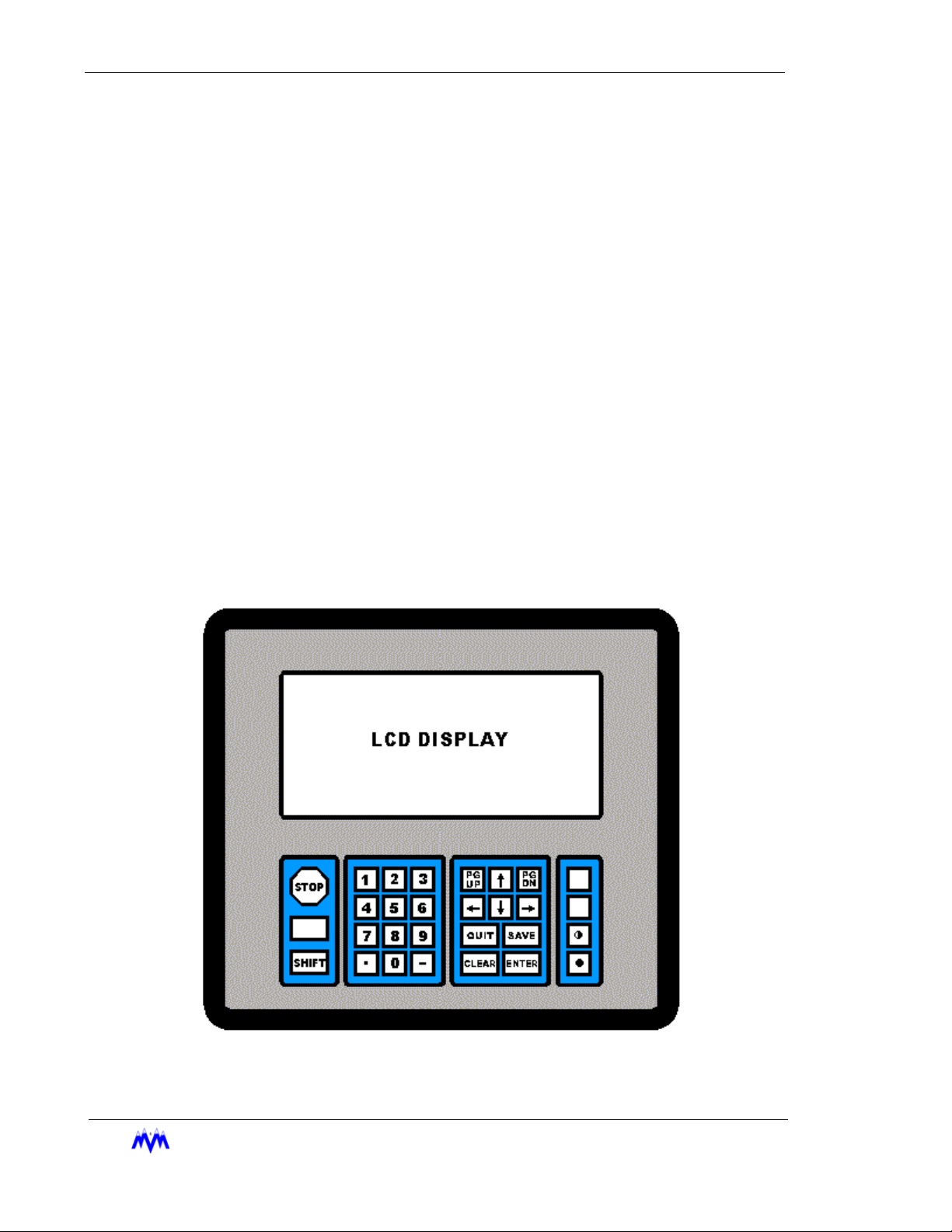
Keypad Functions
The following is a brief summary of the CCS keypad along with a description of its individual
keys. Below is a drawing of the CCS keypad layout.
2-2
M&M R
EFRIGERATION INC
Keypad Diagram
.
Page 17
Chapter 2: Keypad Functions
STOP
SHIFT
0 – 9
•
-
PG UP
PG DN
QUIT
SAVE
CLEAR
ENTER
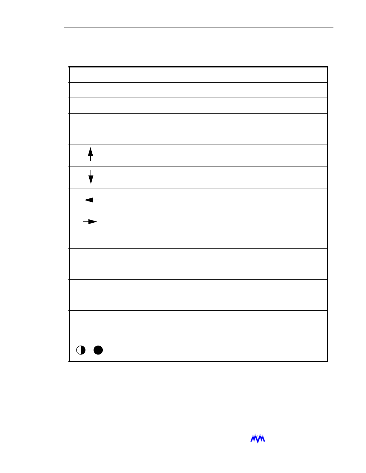
The red STOP key causes an immediate and orderly shutdown of a compressor. This
key usually has no effect on master panels.
The SHIFT key is used to switch control back and forth from the display area to the hot
keys. This key may also be used to scroll between the horizontal pages of a log screen.
The NUMBER keys select menu or hot key options. On data entry screens the number
keys are used to enter numerical data.
The DOT key allows decimal point entry on data entry screens. This key also permits
the user to page forward one full screen at a time on log and status screens.
The MINUS key allows negative number entry on data entry screens. This key also permits the user to page back one full screen at a time on log or status screens.
On data entry or menu screens, the UP ARROW key moves the cursor up to the next
item on the screen.
On data entry or menu screens, the DOWN ARROW key moves the cursor down to the
next item on the screen.
On data entry or menu screens, the LEFT ARROW key moves the cursor left to the next
item on the screen. This key also permits the user to page forward one full screen at a
time on log and status screens.
On data entry or menu screens, the RIGHT ARROW key moves the cursor right to the
next item on the screen. This key also permits the user to page back one full screen at
a time on log and status screens.
The PG UP key is used to page back one full screen at a time for status screens or to
page up to more current data on log screens.
The PG DN key is used to page forward one full screen at a time for status screens or to
page down to older data on log screens.
The QUIT key exits the current screen and displays the previous screen. Pressing the
QUIT key to exit from a data entry screen will result all changed data being lost.
The SAVE key is used with data entry screens to save any changed information. It also
exits the current screen and displays the previous screen.
The CLEAR key within data entry screens will erase the current number field. On the
main status or alarm status screen it acknowledges and clears alarms and failures.
The ENTER key is used within data entry screens on a number field to accept numerical
data or on a selectable field to toggle through the available choices. On menu screens,
the ENTER key will select the highlighted menu item. The ENTER key may also be
used to scroll forward through the status screens.
The CONTRAST keys are used to adjust the display for proper viewing depending on
the ambient light levels. When the desired contrast is achieved, pressing any other key
will lock the current contrast value into memory.
M&M R
EFRIGERATION INC
. 2-3
Page 18
Standard Screw Compressor - RWB Series
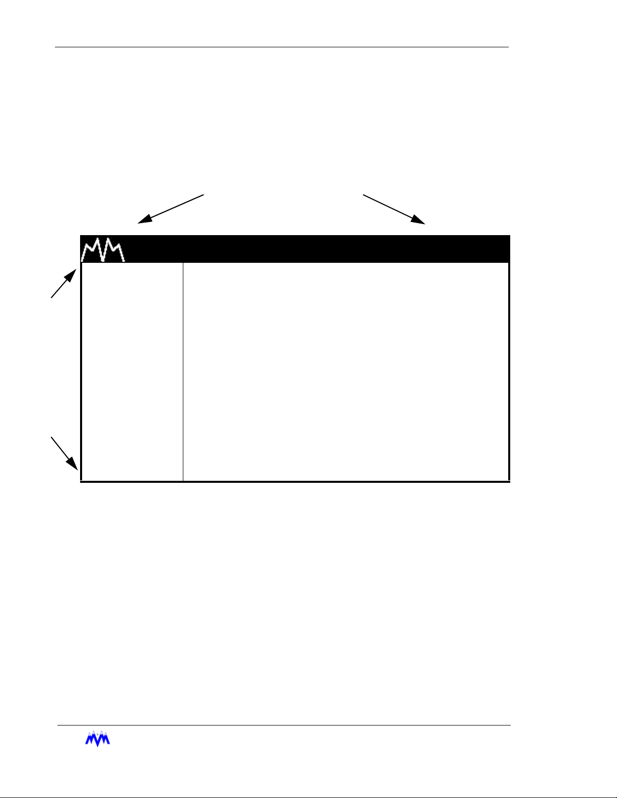
Main Screen Overview
The Main Screen is the name for a set of features common to all large character screens. The
Main Screen is broken down into three areas: display area, hot keys, and title banner. The following drawing shows a representation of the main screen layout and labels each of its various areas.
TITLE BANNER
H
O
T
K
E
Y
S
M & M REFRIGERATION 8:32
1. START
2. STATS
3. MODE
DISPLAY AREA
4. SETPT
5. SCHED
6. CNTRL
7. MISC
8. LOGS
9. MENUS
Main Screen Layout
Title Banner - The top highlighted bar contains the M&M logo and the current time of day and
may only be found on large character screens.
AM
2-4
Display Area - Contains all of the detailed screen information. Large character screens will
use only the designated display area, while small character screens use the entire LCD display.
Hot Keys - The hot keys are a set of system functions, which are found in a column on the left
side of all large character screens. They are the most frequently used functions on the CCS
and allow access to all lower level menus and functions.
EFRIGERATION INC
M&M R
.
Page 19

Chapter 2: Hot Key Selection
Hot Key Selection
1. Verify Number next to a Hot Key is Highlighted - one of the numbers next to a hot
key should be highlighted and flashing. (This is not the same as having the hot key
command highlighted.)
If there are no numbers highlighted, switch control from the display area to the hot
keys by pressing the SHIFT key.
2. Select Option - use the key pad to select a corresponding option number or use the
arrow keys to move the highlighted area to the desired selection and press ENTER.
3. Alternate Select Option - whenever a status screen is being displayed, a hot key
may be activated by typing the hot key number. This also works on small character
status screens even though the hot keys are not visible.
Screen Types
CCS information is presented to the operator using eight different types of screens. The differ-
ent screen types each use specific data entry and control procedures. The screen types let the
user know which screen type heading to refer to for information on the specific screens' procedures. The following is a list of the eight different screen types.
• Menu Screen - displays a numbered list of options.
• Data Entry Screen - used to modify system control parameters.
• Status Screen - displays real-time system summary data.
• Confirmation Screen - used for verification, gives a choice for a yes or no option.
• Momentary Screen - displays a message for three seconds.
• Information Screen - used to display system information
• Access Screen - a menu type screen with an number input field.
• Log Screen - displays a record of system parameters and actions.
M&M R
EFRIGERATION INC
. 2-5
Page 20
Standard Screw Compressor - RWB Series
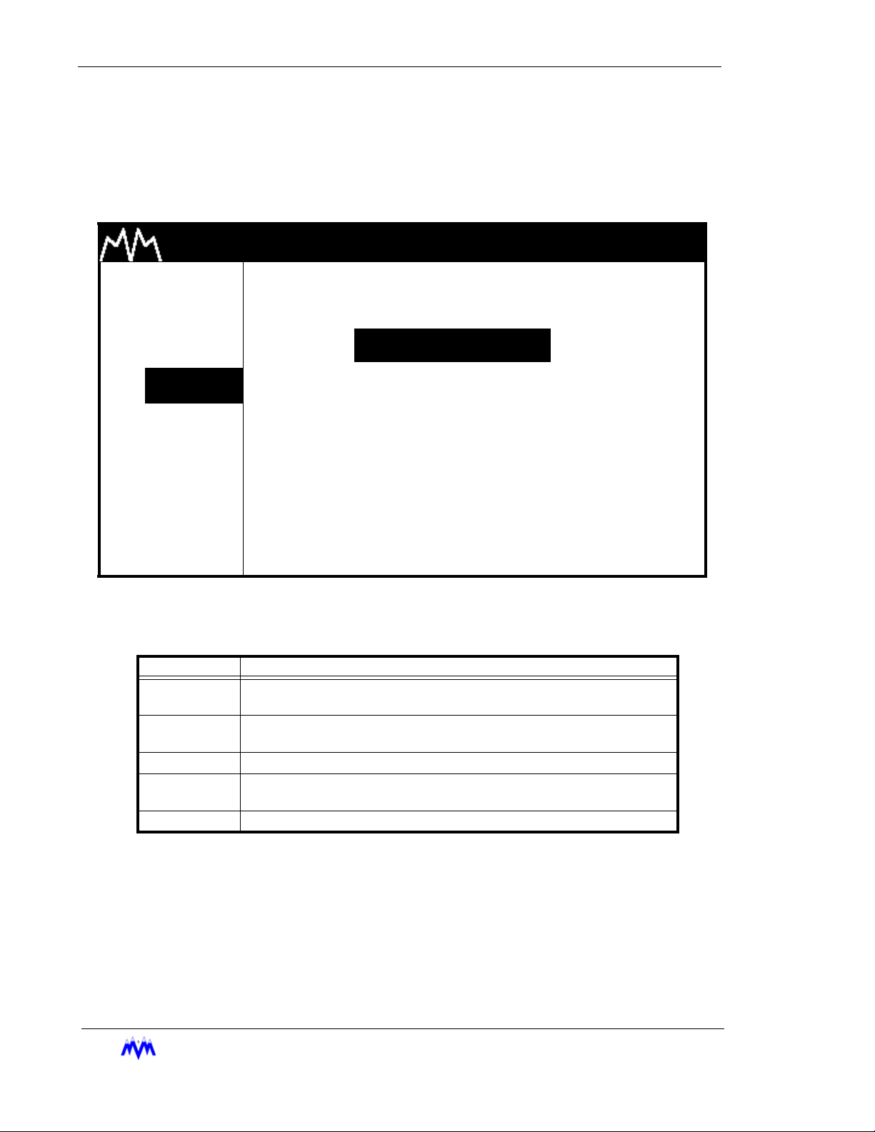
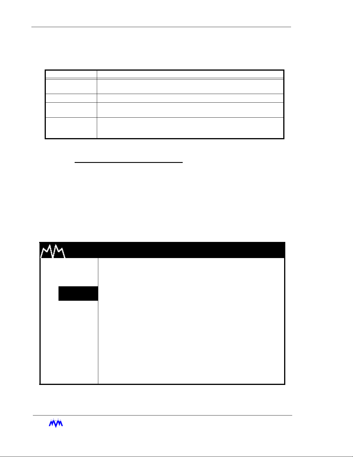
Menu Screens
The Menu screen is used to present the user with choices for various system operations.
Menu screens are found throughout the CCS system. The following is an example of a
menu screen.
M & M REFRIGERATION 8:32
1. START
2. STATS
3. MODE
4. SETPT
5. SCHED
SETPOINT SELECTIONS
1.PRESSURE
2.TEMPERATURE
3.MOTOR CURRENT
6. CNTRL 4.SLIDE VALUE POS
7. MISC
8. LOGS
9. MENUS
Menu Screen
The following table contains a list of the active keys on a menu screen and their function.
AM
2-6
KEYS FUNCTION
SHIFT
NUMBER
KEYPAD
ENTER Used to choose the selection number that is highlighted.
UP/DOWN
ARROW
QUIT Exits from current screen to the previous screen.
EFRIGERATION INC
M&M R
Switches control back and forth between the display area and the hot
keys.
Used to choose a selection number.
Moves the cursor from one selection to the next either up or down.
Menu Screen Keys Table
.
Page 21
Chapter 2: Screen Types
Menu Selection Procedures - Menu options are chosen similar to hot key options.
1. Verify Cursor Control - Verify that a menu option number is highlighted. If not
use the SHIFT key to transfer cursor control from the hot keys to the display area.
2. Menu Option Selection - Use the number keys corresponding to the desired
menu item or the arrow keys and press ENTER to select the desired menu item.
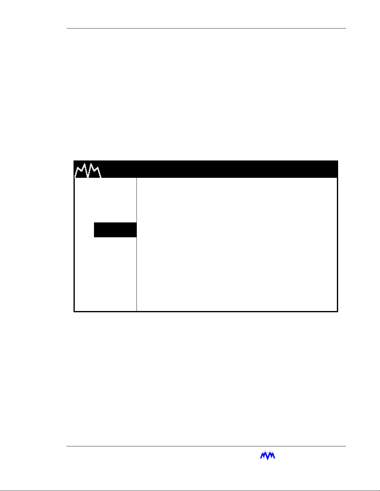
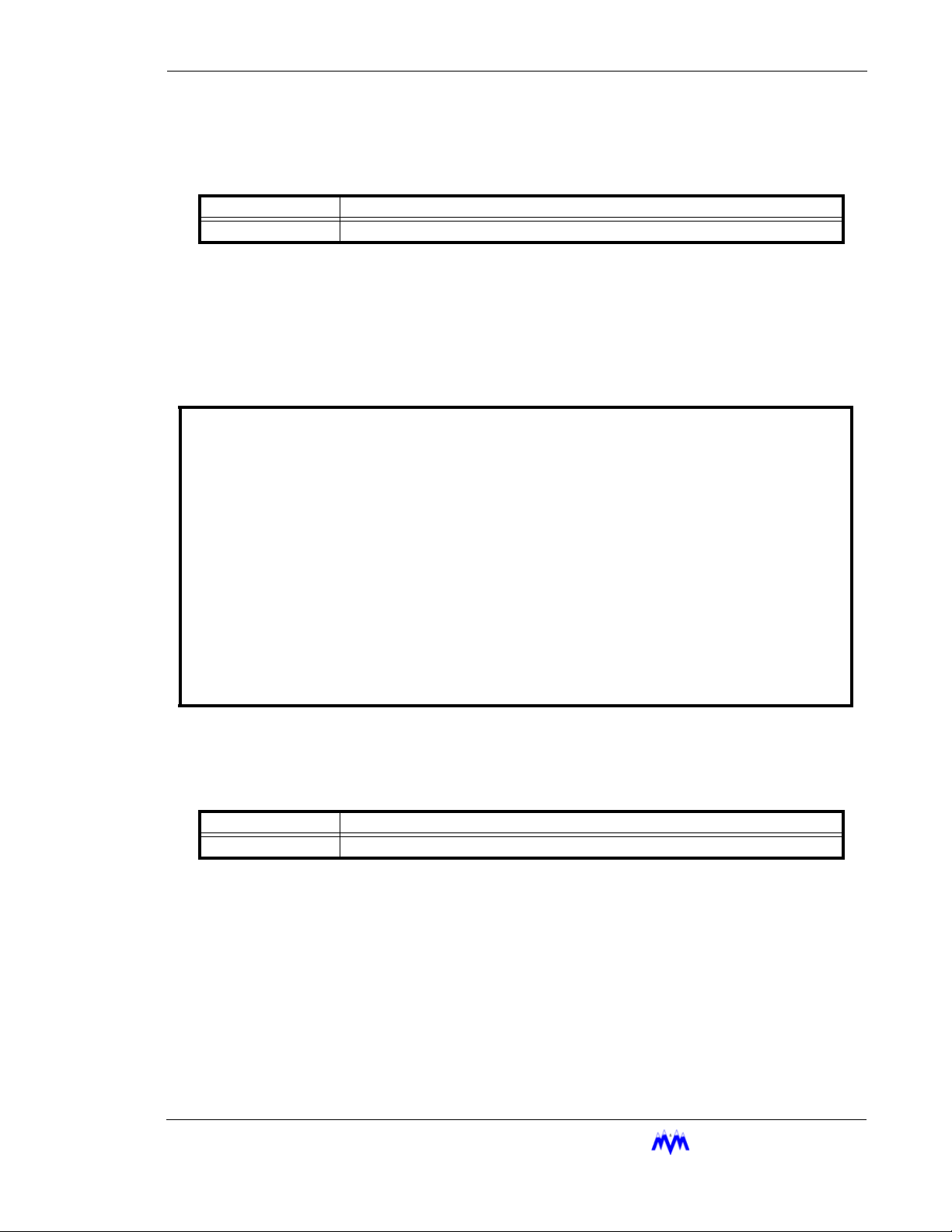
Data Entry Screens
Data Entry screens are user interactive screens, which allow the user to change or input
system data. These screens contain a special cursor to signify the field type at the cursor
location. The cursor can be moved throughout the screen to indicate each field location.
The following is an example of a data entry screen.
M & M REFRIGERATION 8:32
1. START
2. STATS
3. MODE
4.
SETPT
5. SCHED
6. CNTRL
7. MISC
8. LOGS
9. MENUS
NOTE: D
ata Entry screens may also contain information for reference purposes that is not
changeable.
OIL TEMP SETPTS
HIGH FAILURE XXX.X
HIGH ALARM XXX.X
HEATER CONTROL XXX.X
LOW ALARM XXX.X
LOW FAILURE XXX.X
Data Entry Screen
AM
DEGF
DEGF
DEGF
DEGF
DEGF
M&M R
EFRIGERATION INC
. 2-7
Page 22
Standard Screw Compressor - RWB Series
The following table contains a list of the active keys on a data entry screen and their function.
KEYS FUNCTION
NUMBER
KEYPAD
ENTER
ARROW
KEYS
CLEAR
SAVE Exits from the current screen and all new data is saved.
QUIT Exits from the current screen and all new data is lost.
Used to enter numerical data.
Toggles through the available choices on a selectable field. On a number field the
ENTER
Moves the cursor from one field to the next either up, down, left or right. Any of the
arrow keys can also be used to accept the data entered on a number field.
Will clear the current numerical field. The
key is used to accept entered data and move to next field.
A data entry screen may contain both numerical input and selectable fields, which are identified by different cursors as shown in the following table.
CLEAR
Data Screen Keys
key is not active on selectable fields.
CURSOR FUNCTION
> Selectable cursor, indicates a selectable field.
* Numerical input cursor, indicates a number field.
“ String input cursor, indicates an alphanumeric string field.
X Hexadecimal input cursor, indicates hexadecimal number field.
Data Entry Screen Cursor Table
Data Entry Procedures
1. Verify Screen Type - One of the special cursors must appear on the screen. If
the cursor did not appear you are not on a data entry screen.
2. Change Fields - Use the arrow keys to move the cursor to the desired field.
3. Enter Data - Enter the desired numerical data or select the desired selectable
depending on field type.
4. SAVE OR QUIT - Upon completing the changing of data the user may press
SAVE to save all newly entered data and return to the previous screen. If the
user presses QUIT the entered data will not be saved. After pressing QUIT, a
confirmation screen will ask the user to verify the desire to lose all changes
entered.
Field Types
2-8
M&M R
This section discusses the procedures used to work with each of the field types
as well as the general procedures that apply to all number entry fields. The following information applies to any field when entering numerical data:
Decimal Number Entry - If the data you wish to enter has a zero in the decimal
place there is no need to enter " .0 ". Simply enter the whole number value.
EFRIGERATION INC
.
Page 23

Chapter 2: Screen Types
Arrow Keys - The arrow keys will accept the entered data and move the cursor to
the next field.
Errors - A flashing error message tells the user that the entered data is not within
an acceptable range for the field. The user must clear the error before proceeding. To clear an error message the operator presses the CLEAR key.
Restoring Valid Data - The user can clear and re-enter data from any field prior
to leaving the field. If the arrow key or the ENTER key is used to move off the
field after it has been cleared, the previously entered valid data will be restored to
the field.
Selectable Fields
A selectable field gives the user a choice of inputs from which to toggle
through, and is recognized by the ">" cursor preceding it.
1. Verify Cursor Type - locate the ">" selection cursor.
2. ENTER Key - cycles the user through the available selections.
3. Arrow Keys - move to the next field and accept the selection.
Numerical Data Input Fields
A numerical field is used to enter control data, and is recognized by the "*"
cursor preceding it.
1. Verify Cursor Type - locate the "*" numeric input cursor.
2. Number Keypad - press the number keys that correspond to the
number you wish displayed. Use the decimal and minus keys where
applicable. Each field will limit the user to a maximum number of
whole and decimal numbers for that specific field.
3. ENTER/Arrow Keys - move to the next field and accept the entered
number.
4. Verify Cursor Type - Upon pressing the ENTER or DOWN ARROW
key, if the cursor moves across to the units column and changes to
the ">" selectable cursor, the user is in a suction pressure field which
is described in the next section.
Absolute Pressure Fields
This field is actually a combination of numerical and selectable fields. The
selectable or units section of the field allows the user to adjust the units to
select vacuum or non-vacuum ranges.
1. Verify Cursor Type - locate the "*" numeric input cursor.
2. Number Keypad - press the number keys that correspond to the
number you wish displayed. Use the decimal and minus keys where
applicable. If the numeric field already has the correct data and only
the units need to be adjusted, re-enter the existing numerical data
and press ENTER.
EFRIGERATION INC
M&M R
. 2-9
Page 24

Standard Screw Compressor - RWB Series
3. ENTER/Arrow Keys - locks in the numerical data and moves the
cursor across to the units section of the field.
4. Verify Cursor Type - locate the ">" selection cursor next to the units
section.
5. ENTER - cycles between possible units selections.
6. Arrow Keys - move to the next field and accept the entered data.
7. Errors - If an error occurs because the value entered is out of range
the CLEAR key will clear the field and return the user to the number
portion of the field.
Time Fields
The time field is a special case numerical field used to enter time data.
1. Verify Cursor Type - locate the "*" numeric input cursor.
2. Number Keypad - use the number keys to enter the time you wish
displayed. For example, to input the time 5:59 press 0559, the system automatically moves from hours to the minutes. The ":" is automatically entered in a time field. This field will allow for whole number
acceptance. For example to set the time 8:00 the user may type 08
and press ENTER. The time on the screen will appear as 08:00. It
should be noted that time fields may be entered in 12-hour or 24hour format depending on the system configuration. If the system is
in 12-hour format the user will be prompted to select "AM" or "PM"
using a selectable field after a number is entered.
3. Arrow Keys - move to the next field and accept the entered time.
Date Fields
The Date field is a special case numerical entry field used to enter the date.
1. Verify Cursor Type - locate the "*" numeric input cursor.
2. Number Keypad - use the number keys to enter the date you wish
displayed. For example, to enter the date 1/1/91 the user would type
in 010191, the system automatically moves from the month to the
day and then to the year. The "/" slash symbol is entered for you.
3. Arrow Keys - move to the next field and accept the entered date.
String Fields
The String field is a special case alphanumeric entry field. It is similar to a
selectable field but each character in the string may be selected from the list
of all-possible letters, numbers, and special characters.
1. Verify Cursor Type - locate the " “ " string input cursor.
2. Enter Key - Pressing the ENTER key first will clear the current contents and start entering characters. The ENTER key is primarily used
to cycle through the available selections for the current character
positions.
2-10
M&M R
EFRIGERATION INC
.
Page 25

Chapter 2: Screen Types
3. “.” Key - Selecting the Period (.) key puts the field into edit mode
and allows the current contents of the field to be entered.
4. Arrow Keys - Allows you to move within a field to different charac-
ters.
5. Number Keys - These keys are used to enter numbers into a charac-
ter.
6. Clear Key - This key is used to clear the contents of the entire field.
7. Entering a space - If a space is allowed in the field, an “_” will be
available in the character list. Selecting this character will result in a
space being inserted in the string. All trailing spaces are eliminated.
Telephone Number Field
The Telephone Number field is a special case alphanumeric entry field. It is
similar to a string field but only allows numbers and several special characters
required for telephone numbers.
1. Verify Cursor Type - locate the " “ " string input cursor.
2. Enter Key - Pressing the ENTER key first will clear the current contents and start entering characters. The ENTER key is primarily used
to cycle through the available selections for the current character
positions.
3. “.” Key - Selecting the Period (.) key puts the field into edit mode
and allows the current contents of the field to be entered.
4. Arrow Keys - Allows you to move within a field to different charac-
ters.
5. Number Keys - These keys are used to enter numbers into a charac-
ter.
6. Clear Key - This key is used to clear the contents of the entire field.
7. Entering a space - If a space is allowed in the field, an “_” will be
available in the character list. Selecting this character will result in a
space being inserted in the string. All trailing spaces are eliminated.
Hexadecimal Fields
The Hexadecimal Field is a special case alphanumeric entry field. It is similar
to a string field but only allows numbers and several special characters
required for hexadecimal numbers.
1. Verify Cursor Type - locate the " “ " string input cursor.
2. Enter Key - Pressing the ENTER key first will clear the current contents and start entering characters. The ENTER key is primarily used
to cycle through the available selections for the current character
positions.
3. “.” Key - Selecting the Period (.) key puts the field into edit mode
and allows the current contents of the field to be entered.
EFRIGERATION INC
M&M R
. 2-11
Page 26
Standard Screw Compressor - RWB Series
4. Arrow Keys - Allows you to move within a field to different charac-
ters.
5. Number Keys - These keys are used to enter numbers into a char-
acter.
6. Clear Key - This key is used to clear the contens of the entire field.
7. Entering a space - If a space is allowed in the field, an “_” will be
available in the character list. Selecting this character will result in a
space being inserted in the string. All trailing spaces are eliminated.
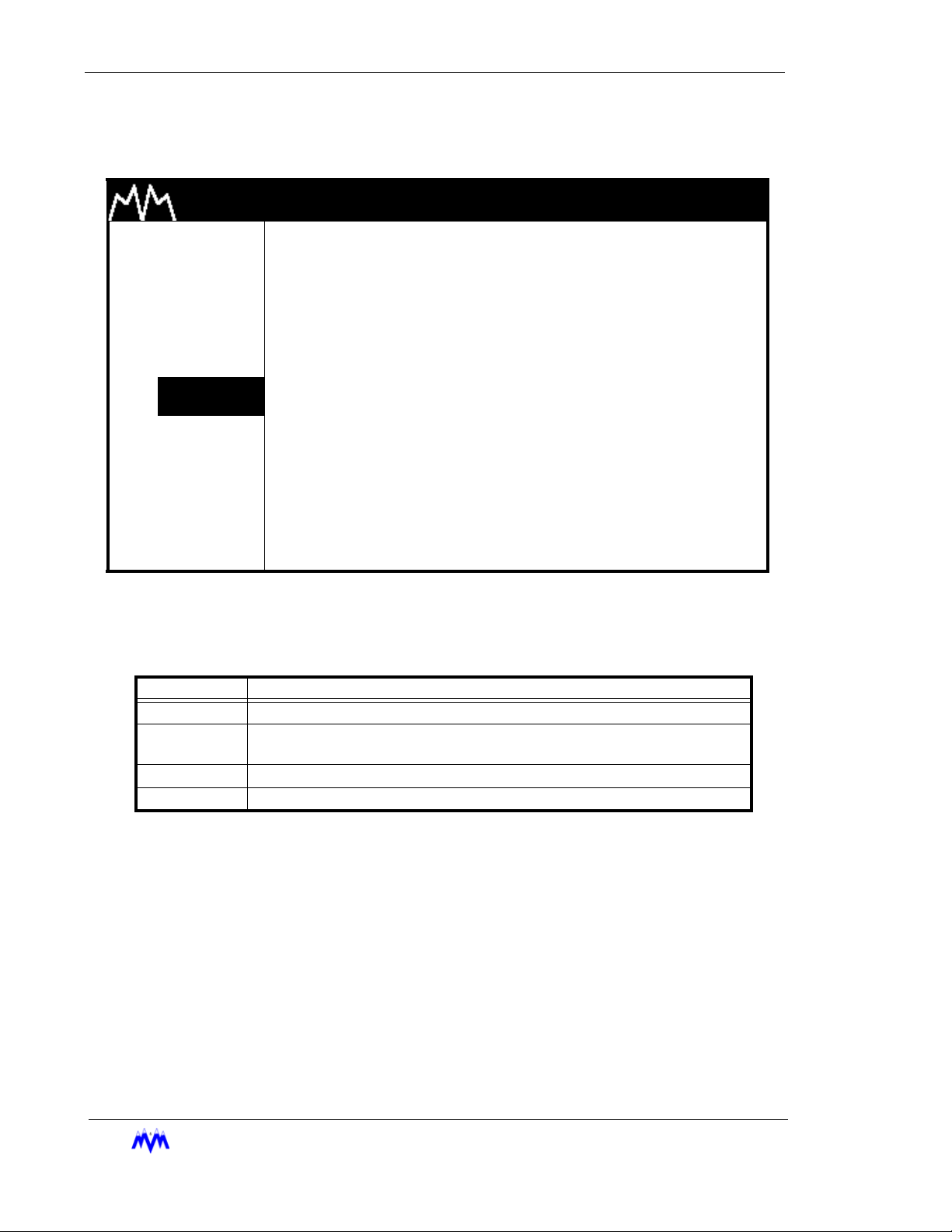
Status Screens
Status screens are used to display a summary of significant system information. The main
Status screen in a system is usually a large character text screen or graphics screen and
is the default screen displayed on the LCD. The main Status screen will be replaced by
the Active Alarm and Failure screen when a new alarm or failure exists or by the AutoStart Warning screen if the compressor is online and ready to start.
The operator may view each of the system's available status screens by scrolling through
using the ENTER, PG UP, PG DN, Right Arrow, or Left Arrow keys. The number of status
screens on a system will vary depending upon the individual system's configuration.
Another feature of the system is that it will automatically return to the main status screen
after 10 minutes of no keyboard activity. Below is an example of a Status screen.
M & M REFRIGERATION 8:32
1. START SY XXX.X
2.
STATS
SP XXX.X
3. MODE DP XXX.X
4. SETPT OP XXX.X
5. SCHED OF XXX.X
6. CNTRL
7. MISC
OF 0.1
SV XXX
PSIG |
PSIG |
PSIG |
PSIG |
PSIG |
PSIG |
PCT |
MA XXX.X
ST XXX.X
DT XXX.X
OT XXX.X
OS XXX.X
PT XXX.X
AMPS
DEGF
DEGF
DEGF
DEGF
DEGF
8. LOGS
9. MENUS RUN-TRIM SEQ NORM
Status Screen
AM
2-12
M&M R
EFRIGERATION INC
.
Page 27
Chapter 2: Screen Types
The following table contains a list of the active keys on a status screen and their function.
KEY FUNCTION
SHIFT Switches control between the display area and the hot key options.
ENTER Scrolls through the set of available status screens.
PG UP/PG DN/
RIGHT/LEFT
ARROWS
QUIT Returns the user to the main status screen.
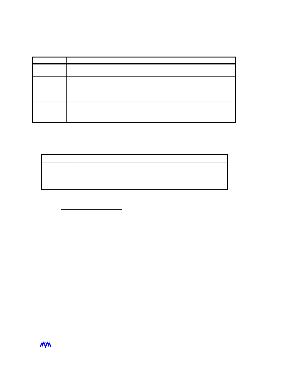
Confirmation Screens
A Confirmation screen is used to ask the user to confirm a selection by answering a question. This screen usually appears after the user has altered system parameters and then
presses the QUIT key or, to verify a system control request. Below is an example of a con-
firmation screen.
Pages forward or back through the available status screens.
Status Screen Keys
M & M REFRIGERATION 8:32
1. START
2. STATS
3. MODE
4. SETPT
5. SCHED
6. CNTRL
7. MISC
8. LOGS
9. MENUS
AM
VERIFY
COMPRESSOR ONLINE
1.NO
2.YES
Confirmation Screen
M&M R
EFRIGERATION INC
. 2-13
Page 28
Standard Screw Compressor - RWB Series
The following table contains a list of the active keys on a confirmation screen and their
function.
KEYS FUNCTION
NUMBER
KEYPAD
ENTER Used to select the highlighted response number.
UP/DOWN
ARROWS
QUIT
Confirmation Screen Procedures
Number Keypad - Use the keypad to match your response with the numerical
choices shown on the screen or press QUIT to exit the screen.
Used to select a response number.
Moves the cursor from one selection to the next, either up or down.
Exits from the current screen to the previous screen. Same as selecting NO for
most screens or YES when quitting from a data entry screen after making
changes.
Confirmation Screen Keys
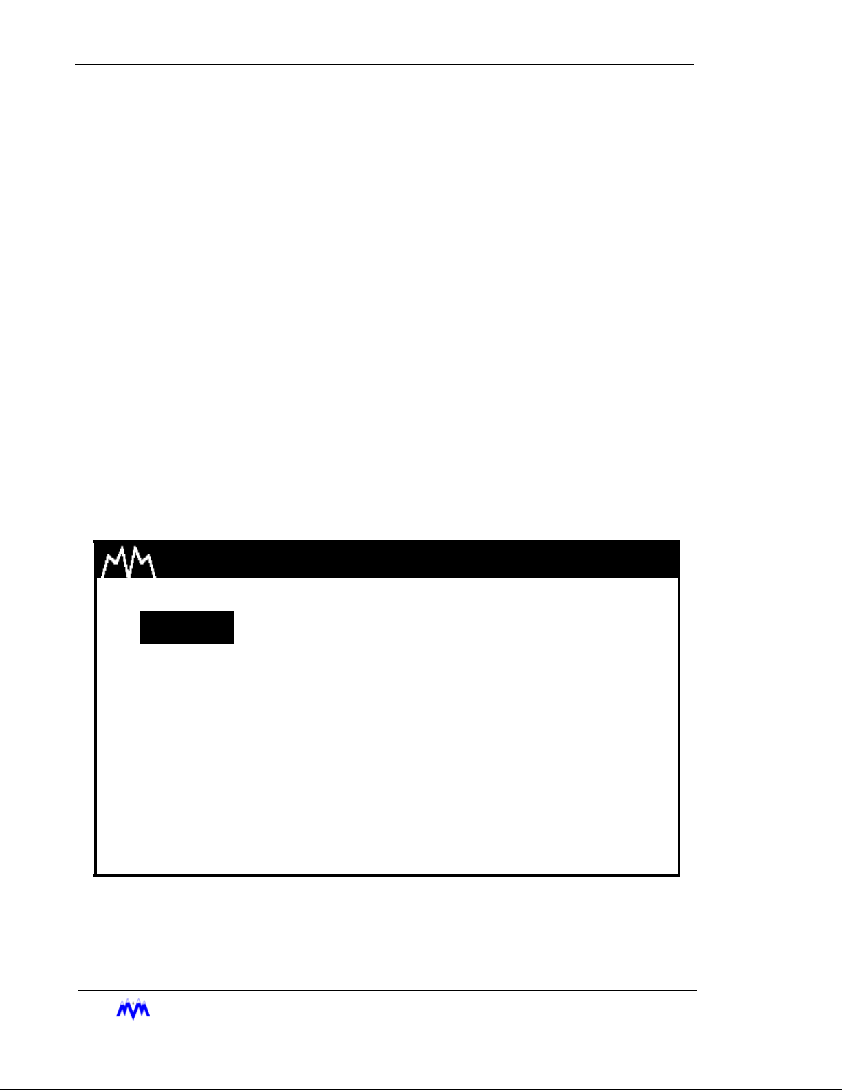
Momentary Screens
The Momentary screen is used to verify certain user selections by displaying an informative message for three seconds. Rather than waiting for the entire three second time to
elapse, the operator may press the QUIT key to end viewing of the message. The follow-
ing is an example of a momentary screen.
M & M REFRIGERATION 8:32
1. START
2. STATS
3. MODE
4. SETPT
5. SCHED
6. CNTRL
7. MISC
8. LOGS
AM
AUTOMATIC MODE
ENABLED
9. MENUS
2-14
M&M R
EFRIGERATION INC
Momentary Screen
.
Page 29
Chapter 2: Screen Types
The following table contains a list of the active keys on a momentary screen and their
function.
KEY FUNCTION
QUIT Stops display of the message before the three second time limit expires.
Momentary Screen Keys
Information Screens
Information screens are used to display system data to the user. The information on
these screens may be real-time data or a snapshot of data at the time the screen is
first displayed.
SYSTEM INFORMATION day mm/dd/yy hh:mm:ss
M & M REFRIGERATION INC, COPYRIGHT 1991-2001 FRAME STATISTICS
F0 F1 F2 F3
M&M SCREW day mm dd yyyy hh:mm:ss v1.00 ---- ---- ---- --- MEMORY INITIALIZED : mm/dd/yy hh:mm:ss MAX : xxxx xxxx xxxx xxxx
SYSTEM LAST RESET : mm/dd/yy hh:mm:ss AVG : xxxx xxxx xxxx xxxx
CURRENT TIME : mm/dd/yy hh:mm:ss day MIN : xxxx xxxx xxxx xxxx
TIMER STATUS : 0 of 0 MAX: 0
REFRIGERANT : R717 SEQUENCED : NO LUBE SYSTEM : NO PUMP
NETWORK CONTROL : NO REMOTE : NO UNLOAD SOL : N/OPEN
BYPASS SOL : NO AUTO-REMOTE : NO
ECONOMIZER SOL : NO PROCESS TEMP : NO
VARIABLE VI : NONE MODEM : NO
Information Screen
The following table contains a list of the active keys on an information screen and their
function.
KEY FUNCTION
QUIT Exits from current screen to the previous screen.
Information Screen Keys
Access Screens
The Access screen is used to index the user into a larger set of screens. This screen is
typically used in cases where more than eight screens are available for a particular option.
The Access screen will perform error checking on the number entered. For example, if the
screen is used to access the daily schedules and the number eight is entered, the input
area will flash ERROR since there are only seven possible schedules. The user will be
M&M R
EFRIGERATION INC
. 2-15
Page 30
Standard Screw Compressor - RWB Series
required to clear the error and enter a correct value. The data entry process is described
in more detail in the data entry section. The following is an example of an access screen.
M & M REFRIGERATION 8:32
1. START
2. STATS
3. MODE
4. SETPT
5. SCHED
6. CNTRL
7. MISC
8. LOGS
9. MENUS
The following table contains a list of the active keys on an access screen and their function.
AM
DAILY SCHEDULES
ENTER SCHEDULE (1-7) xxx
Access Screen
KEYS FUNCTION
SHIFT Switches control back and forth between the display area and the hot keys.
NUMBER
KEYPAD
ENTER Used to accept the selection number that is entered.
QUIT Exits from current screen to the previous screen.
Used to enter a number selection.
Access Screen Keys
2-16
M&M R
EFRIGERATION INC
.
Page 31

Chapter 2: Screen Types
Log Screens
Log screens are used to view recorded system information. The width and length of the
log screens may be wider and longer than allowed by the LCD display area. The arrow
and page keys can then be used to view the entire log. All systems are configured with the
following logs: Operation Log, Trend Log, Alarm Log, Failure Log, and User Log. Other
log types may also be included, depending on system options. Below is an example of a
log screen.
PAGE 1/3 OPERATIONS LOG day mm/dd/yy hh:mm:ss
CNTRL CNTRL
ALARM SETPT PARAM
TIME DATE TYPE ENTRY DESCRIPTION LEVEL #/"/F #/"/F MODE STATE
---------- ----- ----- ------------------- ----- ------ ------ ---- ----------XX:XX:XX XX/XX LOG XXX.X# XXX.X# AUTO RUNNING
XX:XX:XX XX/XX LOG XXX.X# XXX.X# AUTO RUNNING
XX:XX:XX XX/XX LOG XXX.X# XXX.X# AUTO RUNNING
XX:XX:XX XX/XX LOG XXX.X# XXX.X# AUTO RUNNING
XX:XX:XX XX/XX ALARM SUCTION PRESSURE LOW XXX.X# XXX.X# AUTO RUNNING
XX:XX:XX XX/XX LOG XXX.X# XXX.X# AUTO RUNNING
XX:XX:XX XX/XX LOG XXX.X# XXX.X# AUTO RUNNING
XX:XX:XX XX/XX LOG XXX.X# XXX.X# AUTO RUNNING
XX:XX:XX XX/XX START LOCAL KEYPAD XXX.X# XXX.X# AUTO STARTING
↑/↓ = SCROLL, PG UP, PG DOWN, ←/→ = PAGE LEFT/RIGHT, CLEAR = TOP OF PAGE
Log Screen
The following table contains a list of the active keys on a log screen and their function.
KEY FUNCTION
SHIFT Pages horizontally through the information not immediately visible on the log screen.
PG UP/
PG DN
UP/DOWN
ARROWS
RIGHT/LEFT
ARROWS
CLEAR Returns the user to the beginning of the log.
QUIT Exits from current screen to the previous screen.
Allows the user to page forward and back through the log entries. PG UP shows more
recent log entries and PG DN shows older log entries.
Scrolls line by line through the information. The Up arrow shows more recent log entries
and the Down arrow shows older log entries.
Scrolls to additional log pages while maintaining the same time and date for log entries.
Log Screen Keys
M&M R
EFRIGERATION INC
. 2-17
Page 32

Standard Screw Compressor - RWB Series
Alarms & Failures
The CCS continually monitors the system parameters and compares them to alarm and failure setpoints to inform the operator of the system status. An alarm is intended to alert the
operator that an undesirable condition exists. A failure is an indication that a more severe system condition exists and may cause the system or component to shutdown. The system
parameters are compared to both operator-defined setpoints, and M&M Original Equipment
Manufacture (OEM) safety setpoints. An alarm or failure is detected when a system parameter is outside the acceptable range of the setpoints.
Certain alarms and failures may also be suppressed under specific conditions. For example,
the low oil pressure alarm is suppressed when the compressor is not running. Additionally, the
detection of certain alarms and failures can be delayed. For example, the low suction pressure failure is delayed for 10 seconds, in other words the suction pressure must be below the
low failure setpoint for 10 consecutive seconds before the system is shutdown.
Some alarm and failure setpoints are assigned factory default values, which may not be
changed by the operator. These are called OEM safety setpoints and typically indicate a condition that may cause damage to the equipment. A detailed list of all system alarms and failures can be found in Appendix A.
When an alarm or failure is detected the sequence of operations is as follows:
The equipment controlled by the CCS may be stopped, as in the case of a compressor, when
a failure occurs.
The alarm or failure is entered into the active alarm and failure list and the current status
screen on the display is replaced with the active alarm and failure screen.
An entry is made in the appropriate alarm or failure log.
A special entry is made in the operation and trend logs listing the parameter values at the time
of the alarm or failure.
The current alarms and failures present on a system can be viewed on the active alarms &
failures status screen. The operator must acknowledge and clear alarms/failures from this
screen or the main status screen using the procedures covered in this section.
When a new alarm or failure becomes active, the Active Alarm & Failure status screen will be
displayed as the default status screen. The user can view all of the active alarms by scrolling
through the alarms using the up and down arrow keys. An example of the alarm & failure status screen is shown below.
2-18
M&M R
EFRIGERATION INC
.
Page 33

Chapter 2: Alarms & Failures
M & M REFRIGERATION 8:32
1. START
2. STATS
3. MODE
ACTIVE ALARMS & FAILURES
HH:MM:SS TYPE DESCRIPTION STATE
HH:MM:SS TYPE DESCRIPTION STATE
AM
4. SETPT
5. SCHED
6. CNTRL
7. MISC
8. LOGS
9. MENUS state mode alarm
Active Alarms & Failures Status Screen
The active function keys for this screen are described in the following table.
KEY FUNCTION
SHIFT Switches control between the display area and the hot keys.
UP/DOWN
ARROWS
CLEAR
Use the following steps to acknowledge and clear any alarms & failures.
1. Verify Screen Type - The alarm & failure status screen or the main status screen
should be displayed.
2. Acknowledging an Alarm or Failure - Press the CLEAR button. When the CLEAR
button is pressed the previously flashing "ALARM" or "FAIL" in the lower right-hand
corner of the screen will stop flashing and go to a constant highlight. This action will
also deactivate the alarm or failure discrete output. When multiple alarms are active,
the acknowledging function operates on the entire set of active alarms or failures.
3. Correct Problem - The operator must now correct the problem causing the alarm or
failure. This may be a control parameter that is out of range, or various other conditions which should be familiar to the operator.
4. Clear Alarm or Failure - Once the problem is rectified press the CLEAR button on the
keypad. The alarm & failure status area should become non-highlighted and display
the word "NORM", the entry in the active alarm list will also be removed. The clearing
of each alarm is processed when the conditions causing the alarm are acceptable.
Scrolls line by line through the information.
The CLEAR key is used to acknowledge and clear alarms/failures as well as to
silence the alarm horn.
Alarm & Failure Screen Keys
M&M R
EFRIGERATION INC
. 2-19
Page 34

Standard Screw Compressor - RWB Series
2-20
M&M R
EFRIGERATION INC
.
Page 35

CHAPTER 3
Compressor Controls
The following sections discuss the standard and optional features
contained in the CCS Screw Compressor package.
Modes Of Operation
The Screw Compressor package has several modes of operation.
The mode is changed by using the MODE hot key and making a
selection from the operation mode menu. The modes of operation
are as follows:
1. Manual - Starting, Stopping and Capacity Control are all
performed manually.
2. Automatic - Starting and Stopping can be performed man-
ually or automatically based on Suction Pressure or Process Temperature. Capacity Control is performed
automatically to maintain a specific control setpoint.
3. Remote - Starting and Stopping are performed using the
external Remote Start/Stop input or from a remote computer if network communications are enabled. Capacity
Control is performed using external load and unload inputs
or messages from a remote computer. A set of discrete
outputs are available for remote status information.
4. Auto-Remote - Similar to the Automatic mode except starting and stopping are performed using the external Remote
Start/Stop input or messages from a remote computer.
The setpoint group can also be selected from external signals or a remote computer.
5. Sequenced - This mode is utilized when two or more com-
pressors are being used to control the same load.
6. Local - When the compressor is in Local mode, Starting,
Stopping, and Capacity Control are identical to the Manual
mode. The only difference is that when the compressor is
in Local mode, users at remote control locations do not
have the ability to control the compressor or change the
mode.
NOTE: The Remote, Auto-Remote, and Sequenced modes
are available as system options.
M&M R
EFRIGERATION INC
. 3-1
Page 36

Standard Screw Compressor - RWB Series
Lubrication System
The RWB screw compressor is designed to be self-lubricating. The oil being supplied to
the compressor is at discharge pressure and the oil porting to all parts of the compressor
is below discharge pressure. The normal process of gas compression allows the compressor to act as its own oil pump. An oil pump is required to pre-lubricate the bearings
and allow slide valve control during startup. Under operating conditions where the differential pressure (discharge - suction) is too low, a cycling or full lube oil pump is required.
The CCS control for the different lubrication system options is as follows.
Oil Pump Configuration
• Pre-Lube Pump - For normal operations an oil pump is only required to pre-lubricate the bearings and to supply pressure to move the Vi slide stop and the capacity
slide valve when the compressor motor is not running. The pre-lube oil pump is
started before the motor is started and stopped when the starting sequence is complete. The oil pump will be restarted when the compressor is stopped to allow the
slide valve and Vi slide stop to be repositioned in anticipation of the next start.
• Cycling Oil Pump - The cycling oil pump is designed to provide those high stage
applications that operate with normal to low differential pressure ( discharge - suction) with adequate compressor lubrication. The oil pump is started to pre-lubricate
the bearings and to supply pressure to move the Vi slide stop and the capacity slide
valve when the compressor motor is not running. Once the starting sequence is
complete the oil pump is stopped whenever the differential pressure is greater than
95 PSID. The pump will restart whenever the differential pressure drops below 85
PSID.
The pump will turn off once the differential pressure (DP-SP) is greater than 95
PSID. The oil pump will be restarted if the differential pressure drops below 85
PSID.
• Full Lube -The full lube oil pump is used on booster compressors or whenever the
differential ( discharge - suction) is consistently low. The oil pump is started to prelubricate the bearings and to supply pressure to move the slide valve and Vi slide
stop during the starting sequence. The pump remains running until the compressor
is stopped.
The type of oil pump being utilized is configured in the micro processor using Dip
Switches on the main board. Switch bank SW3, switches 1 and 2, are used to
select the configuration as described below:
SW3-1 SW3-2
NOT USED OFF OFF
PRE-LUBE ON OFF
CYCLING OFF ON
FULL LUBE ON ON
3-2
The Oil Pump must be configured using the dip switches that match the installed compressor configuration. This configuration should only be adjusted by qualified personnel.
EFRIGERATION INC
M&M R
.
Page 37

Chapter 3: Starting the Screw Compressor
Oil Pressure Calculations
The Oil Pressure and Oil Filter Pressure values are computed using a combination of the
Oil Pressure After Filter, Oil Pressure Before Filter, and Discharge Pressure transducers.
The following formulas are used:
For a Full Lube Oil Pump the oil pressure is always computed as:
Oil Pressure = Oil Pressure After Filter - Discharge Pressure.
For Cycling and Pre-Lube Pumps:
If the motor is off, Oil Pressure = Oil Pressure After Filter - Discharge Pressure.
If the motor is on, Oil Pressure = Oil Pressure After Filter - Suction Pressure
The Oil Filter Pressure is always computed as:
Oil Filter Pressure = Oil Pressure Before Filter - Oil Pressure After Filter.
Oil Level Indication
When a pre-lube or a cycling oil pump is used, an oil level indicator switch is installed in
the oil separator. This switch opens when the oil level is too low for compressor operation
and the compressor is failed. The level switch is required since the oil pressure is computed as the difference between the oil pressure after filter sensor and suction pressure
sensor when the motor is running. This value could be at normal operating levels even if
oil is not present. When a full time oil pump is used the level switch is not used.
Starting the Screw Compressor
Once a start has been requested, the CCS will delay a minimum of eight (8) seconds before
starting the motor. The minimum start delay is in place to provide the operator an opportunity
to abort the start if unsafe conditions exist.
Once the compressor motor has started, the CCS will delay a minimum of fifteen (15) seconds
before transitioning into the running state. This “up to speed” delay is in place to assure the
motor is turning at full RPM, and allow the system to stabilize from the effects of starting the
motor.
All Alarms and Failures based on sensor values and sensor failures are inhibited during the
“up to speed” delay.
On RWB compressors, the standard oil pressure alarms and failures are inhibited for two (2)
minutes after the motor starts.
Once a start request is made, the microprocessor will unload the slide valve utilizing the
unload solenoid. The slide valve position must be below 5% before the compressor will be
EFRIGERATION INC
M&M R
. 3-3
Page 38

Standard Screw Compressor - RWB Series
allowed to start. If the slide valve position does not move below 5% within 5 minuets, the
compressor will be failed on START SLIDE POSITION. Once the motor starts, the slide valve
position is monitored while the compressor is coming up to speed. If the slide valve position
increases to above 10% during this time, the compressor will be failed on START SLIDE
POSITION also
The oil pressure is checked at all times to assure it is above the OEM minimum (20 PSID for
Full Lube, and 10 PSID for Cycling and Pre-lube) at all times. If the oil pressure drops below
this setting within the first two minutes of operation, this compressor will be failed on OEM
START OIL PRESS LOW.
The sequence for starting the compressor varies based on the Lubrication System configuration as described below:
1. The oil pump is started.
2. The oil pressure must rise above the OEM start oil pressure setpoint and maintain
that pressure for at least 6 seconds. For pre-lube and cycling oil pumps the OEM
start oil pressure setpoint is 5 PSIG. For a full lube oil pump the OEM start oil pressure is 20 PSIG. If the oil pressure fails to exceed these limits within 2 minutes the
start sequence fails on OEM START OIL PRESS LOW.
3. The slide valve is unloaded and must move below 5% before the compressor can
start. If the slide valve does not respond within 2 minutes the start sequence is failed
on START SLIDE POSITION. Unloading is continued while the compressor is start-
ing to assure that the slide valve does not load.
4. The Vi slide stop is decreased to the low Vi position for compressor start.
5. Once the above conditions are met the motor is started and the anti-cycle timer
begins counting.
6. After the motor starts, checks on the oil pressure are delayed for six (6) seconds.
After this initial delay the oil pressure is checked to assure that it remains above the
OEM start oil pressure setpoint ( 5 PSIG for pre-lube and cycling oil pumps and 20
PSIG for full-lube lube oil pumps ).
7. The oil pressure is also checked to assure that it exceeds the OEM transition to run
setpoint. For full-lube oil pumps the setpoint remains 20 PSIG. For cycling or prelube pumps the setpoint is 55 PSIG. If the oil pressure fails to reach these values
within the 2 minute maximum start delay the compressor is failed on START OIL
PRESS LOW.
8. Once all of the above criteria have been achieved the screw compressor will transition into the running state where capacity control can be performed.
The screw compressor can be started manually, automatically, or remotely based on the operating mode chosen. The compressor will not start in any mode if a failure condition exists.
3-4
Manual Mode
Manual Start is accomplished by selecting the START hot key and answering yes to the
start confirmation screen. A manual start is used in Manual mode, Local mode, or Automatic mode when automatic Start/Stop is disabled.
EFRIGERATION INC
M&M R
.
Page 39

Chapter 3: Starting the Screw Compressor
Automatic Mode
In Automatic mode the compressor can be started automatically based on suction pressure or process temperature. Automatic starting is enabled on the Miscellaneous Control
screen under the MISC hot key. Once the Auto Start/Stop feature is enabled the operator
must place the compressor on-line using the START hot key. If the compressor is not
needed at that time it will immediately go to the Cut-Out state and will start automatically
whenever required. If the control parameter is already above the Cut-In setpoint, the compressor will start immediately. A failure or manual stop will take the compressor off-line.
Remote/Auto Remote Mode
I/O Control
When remote operation is desired using discrete I/O signals, the remote Start/Stop
input is used to start and stop the screw compressor in the Remote mode and the
Auto-Remote mode. In both modes, the compressor must first be placed on-line by
the operator through the use of the START hot key. Once the compressor is on-line,
the Remote Start/Stop input may be energized to start the compressor. When the
input is de-energized, the compressor will stop but remain on-line. A failure or manual
stop command will stop the compressor and force it off-line.
NOTE: Before the remote location can control the system, the user must set the operating mode,
and place the screw compressor on-line using the START hot key. Then, and only then, is
the system ready to accept remote control signals.
Network Control
When the Network Communications option is enabled, starting in the Remote or AutoRemote mode is performed using messages from a remote computer. It is required
that the compressor be placed on-line via the keypad or using an on-line message.
For more information on Network Operation, please refer to Appendix C.
Sequenced Mode
In Sequenced mode, the compressor takes commands from an M&M Master Sequencer
Control Panel. The Sequenced mode can be selected from the operating modes menu
under the MODE hot key. Once this mode is selected the screw compressor must be
placed on-line by using the START hot key. Only when the screw compressor is placed
on-line will the CCS respond to control signals from the master sequencer.
M&M R
EFRIGERATION INC
. 3-5
Page 40

Standard Screw Compressor - RWB Series
Stopping the Screw Compressor
The stopping sequence is as follows:
1. The Motor is stopped.
2. Once the starter has disengaged the slide valve is moved to the fully unloaded position (below 5%). If the slide valve does not respond within two (2) minutes, the stop
sequence is failed on OEM STOP SLIDE POSITION HIGH.
3. The Liquid Injection is turned off and the oil temperature is regulated using the oil
heaters.
The screw compressor can be stopped manually or automatically depending on the operating
mode. Any failure will automatically stop the compressor.
Manual Mode
A manual stop is accomplished by using the stop button on the CCS panel. The stop button is active on all screens and causes an immediate shutdown of the motor. Use of the
manual Stop button will also take the compressor off-line.
Automatic Mode
When the Auto Start/Stop feature is enabled and the compressor is in the automatic
mode, the compressor will stop automatically when the control parameter falls below the
cut-out setpoint.
Remote Mode
I/O Control
When remote operation is desired using discrete I/O signals, the Remote Start/Stop
input signal is used to stop the compressor for the Remote and Auto-Remote modes.
When the Remote Start/Stop input is de-energized, the compressor will stop but
remain on-line. A failure or manual stop command will stop the compressor and force
it off-line.
Network Control
When the Network Communications option is enabled, stopping in the Remote and
Auto-Remote modes is performed using messages from a remote computer. Separate messages are available to stop the compressor and leave it on-line, or to stop
the compressor and force it off-line. For more information on network operation,
please refer to Appendix C.
3-6
M&M R
EFRIGERATION INC
.
Page 41

Chapter 3: Capacity Control
Sequenced Mode
When the STOP command is received from the master sequencer, the CCS will stop the
screw compressor automatically and leave it on-line for sequenced operation. While
stopped on-line, the compressor is available for sequencing and in standby waiting for
commands.
Capacity Control
Capacity Control on the screw compressor is performed by adjusting the position of the slide
valve. Loading the slide valve increases the compressor capacity. Unloading the slide valve
decreases the compressor capacity. Capacity Control can be performed manually or automatically depending on the mode of operation.
Computed Slide Valve Position
The RWB compressor utilizes a variable Vi slide stop that dynamically changes the distance of travel of the capacity slide valve. The slide valve position presented to the operator on the main status screen and other screens for reference is automatically adjusted
based on the Vi Slide stop position. Thus the slide valve position shown is always ranged
from 0-100% corresponding to minimal load and full load regardless of Vi position. The
actual sensor readings can be viewed and on the View analog screen.
NOTE: Calibration of the slide valve position should only be done when the Vi slide stop is in the low
Vi position.
Manual Capacity Control
In Manual mode or Local mode the slide valve is adjusted using the keypad on the CCS.
The up-arrow is used to load the slide valve and the down arrow to unload the slide valve.
The CLEAR button is used to stop loading or unloading. Manual capacity control can only
be performed when viewing the main Status screen or the Graphics Status screen.
Automatic Capacity Control
Automatic Capacity Control is accomplished by moving the slide valve to load and unload
the compressor in response to changes in the control parameter (suction pressure or process temperature). The slide valve movement is achieved using a time proportional control strategy. The operator can define Cut-In, Cut-Out, and Control setpoints. These
setpoints are referred to as a control group. The active control group can either be
selected manually by using the active group screen or automatically through setpoint
scheduling. The operator can also define a minimum and maximum slide valve position
which is used as lower and upper limits for the slide valve during automatic capacity control operations.
M&M R
EFRIGERATION INC
. 3-7
Page 42

Standard Screw Compressor - RWB Series
Control Groups
Four groups of control setpoints can be defined for use with automatic capacity control. Each setpoint group consist of a cut-in, cut-out, control, and low alarm and failure setpoints. The control associated with these pressures is as follows;
Cut-Out Setpoint - The CCS will stop the compressor when the suction pressure or
process temperature goes below the cut-out setpoint.
Cut-In Setpoint - The CCS will start the compressor when the suction pressure or
process temperature goes above the cut-in setpoint.
Control Setpoint - The CCS will adjust the slide valve position in an attempt to maintain the suction pressure or process temperature at the control setpoint.
Low Alarm/Failures Setpoints - These are the low suction pressure or process tem-
perature alarm and failure values associated with the control setpoint. In Sequenced
mode, the local setpoints are replaced by the Sequencer low alarm and failure setpoints transmitted by the master sequencer controller.
Time Proportional Control Strategy
The length of time the slide valve is moved during automatic capacity control is determined by a time proportional control strategy. The slide valve move time is proportional to the difference between the control parameter and the control setpoint. The
parameters that define the move time are bandwidth, deadband, short pulse, long
pulse, and slide valve update time. These parameters are defined for both load and
unload conditions by the operator. The definition and description of these parameters
is as follows:
Deadband - When the difference between the control setpoint and the control parameter is less than the deadband value no slide valve movement will take place. If the
deadband values are too small, the slide valve may continuously hunt for the proper
setting very close to the control setpoint resulting in excessive slide valve wear. If the
deadband values are too large, the compressor may not hold the control parameter
close enough to the control setpoint resulting in inefficient capacity control.
Short Pulse - This is the shortest amount of time the slide valve is moved to load or
unload the system. The short pulse time is the fine adjustment for control parameter
differentials slightly above or below the deadband values. If the shortest pulse is too
long the slide valve may continuously overshoot the optimal position resulting in
excessive slide valve wear.
Bandwidth - This parameter adjusts the overall sensitivity of the control strategy. The
slide valve move time is computed to be between the shortest and longest pulse while
the control parameter is outside the deadband but inside the bandwidth. The move
time approaches the longest pulse time as the difference between the control parameter and the control setpoint approaches the bandwidth value. If the bandwidth value
is too small, the compressor will respond quickly and may constantly overshoot the
optimal position. If the bandwidth values are too large the compressor will react
3-8
M&M R
EFRIGERATION INC
.
Page 43

Chapter 3: Capacity Control
slowly to control parameter changes. While the control parameter is outside the bandwidth values the slide valve is continuously loaded or unloaded.
Long Pulse - This is the longest amount of time used to move the slide valve while
loading or unloading the compressor. This time period is used when the control
parameter differential is equal to the bandwidth value. If the longest pulse is too long
the compressor may overshoot the optimal position. If the value is too short the slide
valve will react slowly to large changes in the control parameter.
Update Time - This is the time interval between computations of slide valve move
time. Once a required move time is calculated the CCS waits the update time interval
before another computation is made. This time is normally greater than or equal to
the long pulse.
The relationship of these parameters can be seen in the time proportional control
strategy diagrams shown below:
M&M R
EFRIGERATION INC
. 3-9
Page 44

Standard Screw Compressor - RWB Series
Pressure Difference
Above Setpoint
Load Bandwidth
Slide Valve Movement Time
Continous Load
Computed Based on
Pressure Difference
Load Deadband
Unload Deadband
Unload Bandwidth
Pressure Difference
Below Setpoint
Long Pulse
Short Pulse
No Slide Valve Movement
No Slide Valve Movement
Slide Valve Movement Time
Computed Based on
Pressure Difference
Continous Unload
Control Setpoint
3-10
Slide Valve
Movement Time
M&M R
Time Proportional Control Strategy Diagrams
EFRIGERATION INC
.
Deadband Bandwidth
Pressure Difference from Setpoint
Page 45

Chapter 3: Capacity Control
Remote Capacity Control
I/O Control
When remote operation is desired using discrete I/O signals, and the compressor is in
the Remote mode, capacity control is performed using the Remote Load and Remote
Unload inputs. The relationship of these signals to slide valve movement is shown in
the following table.
NOTE: Remote Capacity Control is only active while the screw compressor is running.
REMOTE LOAD REMOTE UNLOAD SLIDE VALVE MOVEMENT
Low Low Holding
High Low Loading
Low High Unloading
High High (Should not be used)
Network Control
When the Network Communications option is enabled, and the compressor is in the
Remote mode, capacity control is performed using load and unload messages from a
remote computer. For more information on network operation, please refer to Appendix C.
Auto-Remote Capacity Control
I/O Control
When remote operation is desired using discrete I/O signals, and the compressor is in
the Auto-Remote mode, capacity control is performed using Automatic Capacity Control. Remote Setpoint signals A and B are used to select the current active setpoint
group to be used for automatic capacity control in the Auto-Remote mode. The input
settings for the different group numbers are shown in the following table.
GROUP
NUMBER
1LowLow
2HighLow
3LowHigh
4 High High
The operator can enable and disable Remote setpoint selection from the Miscellaneous Control screen under the MISC hot key.
REMOTE SET-
POINT A
REMOTE SET-
POINT B
NOTE: Scheduling should be disabled when the Remote setpoint selection feature is enabled.
EFRIGERATION INC
M&M R
. 3-11
Page 46

Standard Screw Compressor - RWB Series
Network Control
When the Network Communications option is enabled, and the compressor is in the
Auto-Remote mode, capacity control is performed using Automatic Capacity Control.
The control setpoint is selected using setpoint messages from a remote computer.
Sequenced Capacity Control
While in the Sequenced mode, Automatic Capacity Control is used to adjust the slide
valve as documented above. When a sequenced compressor is on-line, one of the following three commands will be sent from the master sequencer controller.
• Trim When the trim command is sent from the master sequencer, the CCS
will start the screw compressor. The Control Parameter and Control
Setpoint will be also be sent from the master, and the compressor will
begin making slide valve adjustments using Automatic Capacity Control. Once the compressor is started, the status area will display
RUN-TRIM indicating that the trim command was received.
• Full Load When the Full Load command is sent from the master sequencer, the
CCS will force and hold the slide valve at the fully loaded position.
When the Full Load command has been received, the status area will
display FULL LOAD.
• Seq-Stop When the Seq Stop command is received from the master sequencer
the CCS will stop the screw compressor automatically and leave it
on-line for sequenced operation.
Low Alarm and Failure Setpoints
When Sequenced mode is enabled and the compressor is online or running, the local
low alarm and failure setpoints are replaced by the Sequencer low alarm and failure
setpoints. This is true for both Suction Pressure and Process Temperature operation.
The local sensor is still used to generate the alarm or failure condition.
Running in Trim Mode
When the trim command is sent from the master sequencer the CCS receives the
System Control Parameter, System Control Setpoint, and the sequencer load and
unload deadband and bandwidth parameters. These new control parameters are
used instead of those defined on the CCS itself. The compressor’s local long-pulse,
short-pulse, and update time are used for slide valve movement.
The main status page will identify the control setpoint group as SY indicating that it is
the System Control Setpoint. Automatic Capacity Control is used to adjust the slide
valve while in Sequenced mode. The System Control Parameter, System Control setpoints, and Low Alarm and Failure setpoints are sent to the compressor periodically
by the master sequencer to ensure that the compressor is always using current data.
All automatic starting and stopping of the screw compressor is controlled by the master sequencer. The local screw's Cut-In and Cut-Out controls are also disabled. When
the screw compressor is fully loaded, limited, or forced to unload due to high Motor
3-12
M&M R
EFRIGERATION INC
.
Page 47

Chapter 3: Capacity Control
Current, the CCS informs the master sequencer that no further capacity increases are
possible and additional compressors may be needed.
Running in Full Load Mode
When the Full Load command is received the CCS disables all capacity control and
locks the slide valve at the fully loaded position. However, normal limiting and unloading functions will still be active.
Anti-Cycle in Sequenced Mode
While in the Sequenced mode the anti-cycle time takes on a new role. If the master
sequencer requests a screw compressor to stop but time is still remaining on the anticycle timer, the compressor will not stop. The compressor will remain running, at its
minimum slide valve position, until the anti-cycle timer expires. This procedure
ensures that the compressor is always available for the next sequenced start. If the
compressor should be stopped manually, or due to a failure, with time remaining on
the anti-cycle timer it would then be unavailable for sequencing until the timer expires.
Forced Unloading & Limiting
Forced Unloading and Limiting are performed to protect the system under extreme conditions or to slow-down the rate of capacity increase. The CCS may unload the compressor
or limit loading of the compressor due to high motor current or high discharge pressure. In
the Manual mode of operation, only high motor current limiting and forced unloading is
enabled. Forced unloading and limiting will cancel any ongoing capacity control movements of the slide valve. If a parameter exceeds the high limit setpoint the compressor
will be limited (not allowed to load). If a parameter exceeds the high unload setpoint the
compressor will be forced to unload until the parameter is reduced.
Ramp Start
Ramp Start adjusts the forced unloading and limiting setpoints during a period of time
after the compressor is started. Ramp start is used to reduce the demand power requirements during compressor startup. Each high unload and high limit setpoint has associated
with it a similar ramp unload and ramp limit setpoint. Also associated with each different
parameter is a ramp duration time. After the compressor has started, the forced unloading
and limiting setpoints are gradually changed from the ramp setpoints to the high setpoints
during the ramp duration time. The Discharge Pressure Ramp Start parameters are setup
on the Discharge Pressure Setpoints screen under the SETPT hot key. The Motor Current
Ramp Start parameters are setup on the Motor Current Setpoints screen under the
SETPT hot key.
The relationship of the ramp start feature to unloading and limiting can be seen in the following figure.
M&M R
EFRIGERATION INC
. 3-13
Page 48

Standard Screw Compressor - RWB Series
Compressor is Unloaded
High Unload
High Limit
Ramp Unload
Ramp Limit
Parameter
Value
Compressor is Limited
Compressor
Start
Ramp
Duration
Time After Compressor Start
Ramp Figure
Slide Valve Position Ramp Start Limiting
The Slide Valve Position Ramp Start feature has been provided to limit capacity increases
after the compressor starts. The operator can define the minimum positions to start ramping, the total time to limit capacity increases and the maximum position. Once the compressor is started the capacity ramp timer is started, and the capacity will be allowed to
increase to the minimum position as soon as required. Once at the minimum, capacity
increases will be limited. The maximum allowable position of the slide valve will be gradually increased from the minimum position to the maximum position over the ramp duration. When the capacity is limited due to this feature, the screw state will display
“LIMIT:SV”. Unlike other limiting and unloading, the compressor is not considered fully
loaded when in this state. This feature is available in Automatic, Auto-Remote and
Sequenced mode. When in sequenced mode, the capacity ramp is also used to limit
movement of the slide valve when the compressor is a fully loaded machine. If a fully
loaded compressor is forced to unload for any reason, the capacity ramp will engage from
the current slide valve position once capacity control resumes. The capacity ramp start
parameters are set-up on the slide valve position setpoint screen.
EFRIGERATION INC
3-14
M&M R
.
Page 49

Chapter 3: Setpoint Scheduling
Unload Solenoid Configuration
The unload solenoid for the A -Series compressors has two configurations, In the
original configuration, the solenoid is normally closed, energized to unload the compressor. In later versions, the unload solenoid is normally open, and is de-energized
to unload the compressor. The advantage of this new valve configuration is that when
power is lost to the compressor, the unit will naturally unload. The type of valve being
used is configured using a dip switch on the main board. When SW3 switch #4 is on,
the valves are assumed to be normally closed. When Sw3 switch #4 is off, the valves
are assumed to be normally open. If the unload solenoid is normally open (energize
to close), the word "(REV)" will be present on the view I/O screen indicating reverse
acting.
Setpoint Scheduling
Setpoint scheduling is the automatic switching of Suction Pressure or Process Temperature
control setpoint groups based on time of the day and day of the week. The operator can define
up to seven (7) different daily time schedules and one weekly schedule. Schedule events can
be manually overridden and scheduling can be enabled or disabled by the operator. Setup of
schedules and control of the scheduling is performed under the SETPT hot key.
Daily Schedules
Each daily time schedule consists of up to eight (8) different time-of-day slots. For each
time-of-day slot the operator can define the time (either in 12 or 24 hour mode, depending
on system clock mode selected) and the desired setpoint group number. Unused time
slots are ignored and the schedule may be entered in any order. When the schedule is
saved it is reordered chronologically. Each daily schedule is identified by a schedule
name (SCH1 - SCH7).
Weekly Schedule
The weekly schedule allows the operator to assign different daily schedules to each day of
the week. A new day begins and schedules change at midnight. The current daily schedule or control group may be overridden by the operator at anytime. Any item which has
been manually overridden will be changed when the next schedule change occurs.
M&M R
EFRIGERATION INC
. 3-15
Page 50

Standard Screw Compressor - RWB Series
Variable Vi Slide Stop Control
Vi refers to the volumetric ratio of the screw compressor. The Vi is computed by taking the
ratio of the volume of gas when compression begins to the volume of gas when discharge
begins. In a fixed Vi screw compressor the Vi is determined by the size of the discharge port
and must be matched to the operating conditions of the system. If the operating conditions
change the compressor will operate at a reduced efficiency due to over compression or under
compression of the gas. The RWB screw compressors contains an additional hydraulic piston
which adjusts the size of the discharge port. The Vi slide stop is adjusted in response to operating condition changes to increase compressor efficiency and reduce operating cost. The
RWB Vi slide stop ranges from a setting of 2.2 to 5.0.
Vi Adjustments
The Vi slide stop is adjusted by the CCS based on the ratio between discharge pres-
sure and suction pressure. The Vi slide stop adjustments are performed periodically
based on a Vi update timer or when requested by the operator. The duration of the Vi
update time is user programmable. Once the timer expires an adjustment is made.
During Vi adjustments, no capacity control operations are performed. While the compressor is starting and for 3 minutes after it is running Vi adjustments are disabled.
Manual Vi Adjustment
In every mode except manual, the CCS adjust the Vi automatically every time the Vi
update timer expires. The operator can force a Vi adjustment in every mode from the
Vi status screen. When either of the arrow keys is pressed from the Vi status screen
a Vi adjustment is started immediately.
Vi Slide Stop and Capacity Slide Valve Interference
The adjustments of the Vi slide stop limits the travel of the capacity slide valve. If high Vi
is required, the capacity slide valve will only be able to load to a 60% indicated position.
When the capacity slide valve is at 60% and the Vi slide stop is at the high Vi position the
compressor is at full-load high Vi. If low Vi is required the capacity slide valve is able to
load to 100% indicated position. When the capacity slide valve is at 100% and the Vi
slide valve is at the low Vi position the system is at full-load low Vi. Intermediate Vi positions will restrict the movement of the capacity slide valve between 60% and 100%. The
capacity of the compressor is the same at full-load high Vi and full-load low Vi. The interference of the Vi and capacity slide valve requires that the capacity slide valve be moved
along with the Vi slide valve when above 60% indicated.
VI Position Correction
The RWB compressor Vi slide stop indicator measures the linear position of the Vi slide
stop along its range of travel. This sensor value is then corrected based on the Vi non linear characteristics to produce a corrected Vi position. The corrected Vi position is what is
displayed on status screens and recorded in the logs. The actual sensor readings can be
viewed and on the View analog screen.
3-16
NOTE: Calibration of the Vi position should only be done using the endpoints (Minimum Vi and Max-
imum Vi). It should never be calibrated at some mid position.
EFRIGERATION INC
M&M R
.
Page 51

Chapter 3: Oil Temperature Regulation
Oil Temperature Regulation
The oil temperature in the oil separator is regulated when the screw compressor is stopped.
The temperature is maintained above the oil heater setpoint with a deadband of +5 degrees.
When the compressor is stopped and the Oil Sump Temperature falls below the Heater Control setpoint, the oil heaters will be turned on. When the Oil Sump Temperature rises 5 degrees
above the Heater Control setpoint, the oil heaters will be turned off. The Heater Control setpoint may be found on the Oil Temperature Setpoints screen under the SETPT hot key.
Liquid Injection Oil Cooling (Option)
The RWB screw compressor may be configured for single port or dual port liquid injection
cooling. When either of the liquid injection options is installed, two additional setpoints will
appear on the oil temperature setpoint screen. The liquid injection cut-in setpoint defines the
oil temperature at which liquid injection will be started. The liquid injection cut-out setpoint
defines the oil temperature at which liquid injection will be stopped.
The RWB CCS is configured for dual port liquid injection whenever the liquid injection option is
installed. All solenoid outputs will be generated but if no solenoid is attached to the output the
signal is ignored.
Single Port Liquid Injection
Single port liquid injection uses one main injection solenoid which is opened and closed
based on oil temperature whenever the motor is running.
Dual Port Liquid Injection
Dual port liquid injection utilizes a main injection solenoid and a second solenoid to switch
between a low Vi and a high Vi injection port. The main injection solenoid is open and
closed based on temperature whenever the motor is running. The high/low Vi solenoid is
controlled based on the current Vi setting. When the Vi is above 3.5 the high/Low Vi solenoid is energized. When the Vi is below 3.5 the high/low Vi solenoid will be de-energized.
Both solenoids will be de-energized when the motor is stopped.
Anti-Cycle Timer
The Anti-Cycle timer is used to avoid repeated start attempts within a 20 minute period of time.
The Anti-Cycle timer is started with the motor and must completely count down before the
motor can be started again. The time period is not adjustable by the operator.
M&M R
EFRIGERATION INC
. 3-17
Page 52

Standard Screw Compressor - RWB Series
Power Fail Restart
The operator can define a power fail restart time from the miscellaneous time setpoint screen.
If the CCS is reset manually or due to a loss of power the down time is calculated and compared to this setpoint. If power was off longer than the power fail restart time a failure is
reported. If the power loss was less then the setpoint no failure is reported and the compressor remains on-line and is allowed to automatically restart if required.
Remote Status Information
The Remote option provides for a group of discrete outputs for Remote status information. The list of Remote status outputs is as follows.
REMOTE STATUS
OUTPUT
LIMITED
ANTI-CYCLE
LOAD
LIMITED
MINIMAL
LOAD
INTERMEDIATE
LOAD
FULL
LOAD
ALARM A high signal indicates an alarm is active.
FAIL A high signal indicates a failure is active.
ON-LINE A high signal indicates the screw compressor is on-line for remote operations.
A high signal indicates the screw compressor cannot be started due to the anticycle timer.
A high signal indicates the screw compressor is currently limited or being
forced to unload due to high motor current, high discharge pressure, or capacity ramp.
A high signal indicates the slide valve is above the minimal load position.
A high signal indicates the slide valve is above the intermediate load position.
A high signal indicates the slide valve is fully loaded.
DESCRIPTION
The minimal and intermediate load positions can be defined using the Remote Slide Valve
Setup screen from the Configuration menu. This allows the operator to adjust the remote
slide valve outputs to the needs of the facility.
3-18
Process Temperature Control (Option)
When the Process Temperature option is enabled, the screw compressor slide valve position
is adjusted to maintain the outlet temperature of a product or process instead of suction pressure (e.g. chiller outlet temperature control). The control strategy is documented in the
Capacity Control section above.
EFRIGERATION INC
M&M R
.
Page 53

Chapter 3: Economizer Control (Option)
Economizer Control (Option)
The Economizer Control option provides an intermediate pressure port located between the
primary suction and discharge ports on the screw compressor. The Economizer Solenoid output is used to control the flow of liquid into the economizer vessel or to control a suction solenoid at the economizer port.
The Economizer Solenoid output may be forced on, forced off, controlled automatically based
on the slide valve position, or sequenced by the master sequencer. The Economizer mode
(AUTO, MAN ON, MAN OFF, or SEQ) and automatic control setpoints can be adjusted from
the Economizer Control screen under the CNTRL hot key.
Automatic Mode
In Automatic mode, the Economizer Solenoid is controlled based on the slide valve position of the compressor. When the compressor is running and the slide valve position is
above the cut-in setpoint, the Economizer Solenoid will be energized. When the slide
valve position drops below the cut-out setpoint or the compressor is stopped, the Economizer Solenoid will be de-energized.
Manual On Mode
When the Economizer Control is in the Manual On mode, the Economizer Output is energized whenever the compressor is running.
Manual Off Mode
When the Economizer Control is in the Manual Off mode, the Economizer Output is deenergized at all times.
Sequenced Mode
When the Economizer Control is in the Sequenced mode, the Economizer Output is controlled by the master sequencer controller at the master control panel.
Power Assist (Option)
In low temperature booster applications, more positive suction check valve closure may be
needed. The power assist option supplies this positive closure by allowing high pressure gas
to assist the spring tension of the check valve. The high pressure gas supply is typically taken
from the high stage discharge. When the compressor stops, high pressure gas is vented to
the suction check by opening the power assist solenoid. The solenoid is held open for 30 seconds. The compressor will remain in the stopping state until the power assist solenoid is
closed.
M&M R
EFRIGERATION INC
. 3-19
Page 54

Standard Screw Compressor - RWB Series
Operational Procedures
The operator interface for the screw compressor is performed using LCD, keypad, and the following nine hot keys:
•START
•STATS
•MODE
•SETPT
•SCHED
• CNTRL
•MISC
•LOGS
•MENUS
The following sections will explain the operating procedures associated with each of these hot
keys. If additional plant control functions are present in the controller, some or all of the above
functions may be listed under a separate hot key called SCREW. Additional hot keys that
may be present on a system will be discussed in separate documents.
START Hot Key
The START hot key begins the compressor start sequence for the modes which require
starting from the keypad. The other operational modes will require the use of the START
hot key to put the compressor on-line. A confirmation screen appears after the START hot
key option is selected to verify the action.
M & M REFRIGERATION 8:32
1. START
2. STATS VERIFY
3. MODE START COMPRESSOR
4. SETPT 1.NO
5. SCHED 2.YES
6. CNTRL
7. MISC
8. LOGS
AM
9. MENUS
3-20
M&M R
EFRIGERATION INC
Start Confirmation Screen
.
Page 55

Chapter 3: Operational Procedures
The following screen is an example of one of the possible momentary screens that may
appear after answering yes to the Start Confirmation screen. The possible momentary
screens will vary depending on the individual system configuration.
M & M REFRIGERATION 8:32
1.
START
2. STATS
3. MODE STARTING
4. SETPT
5. SCHED MANUAL MODE
6. CNTRL
7. MISC
8. LOGS
9. MENUS
Start Momentary Screen
The following table lists possible momentary screens associated with the START hot key.
SCREEN FUNCTION
STARTING LOCAL MODE The compressor is starting in the Local mode.
STARTING MANUAL MODE The compressor is starting in the Manual mode.
STARTING AUTOMATIC MODE The compressor is starting in the Automatic mode.
ON-LINE REMOTE MODE
ON-LINE AUTO-REMOTE
MODE
ON-LINE SEQUENCED MODE
START DISABLED ALREADY
IN PROGRESS
START DISABLED
SYSTEM IS RUNNING
START DISABLED ANTI-
CYCLE XX:XX
START DISABLED
SYSTEM ALARM/FAILURE
The compressor is on-line in the Remote mode and may start, depending
on the state of the Remote Start/Stop input.
The compressor is on-line in the Auto-Remote mode and may start,
depending on the state of the Remote Start/Stop input.
The compressor is on-line in the Sequenced mode and may start, depending on the master sequencer.
The start function is disabled because the compressor is already in the
process of undergoing the start-up operation.
The start function is disabled because the compressor is already running.
The compressor is delayed from starting. An anti-cycle timer has been
activated which prevents start-up until the 20 minute time period has
expired (XX:XX is the time remaining). The screen will continue to be displayed until the timer expires or the user presses the QUIT key.
The start function is disabled due to a system alarm or failure.
AM
M&M R
EFRIGERATION INC
. 3-21
Page 56

Standard Screw Compressor - RWB Series
STATS Hot Key
The STATS hot key will allow the user to return quickly to the main Status screen. The
operator may select the Compressor Status screen or the Compressor Graphics screen
as the default main Status screen. The Quit key will always return the user to the currently
selected main Status screen. Subsequent uses of the QUIT key will toggle between the
Compressor Status screen and the Compressor Graphics screen.
Compressor Main Status Screen
The Compressor Status screen shows a numerical summary of the compressor analog and state parameters. The values are continuously updated in real-time to reflect
the current state of the compressor. For example, in the figure below the current state
of the system is RUN-TRIM. The system's mode of operation is SEQ (Sequenced)
and the alarm status of the system is NORM (normal). There are also two system
functions which may be performed from this screen: Slide valve adjustment when in
Manual or Local modes and the clearing of alarms and failures.
M & M REFRIGERATION 8:32
1. START SY XXX.X
2.
STATS
SP XXX.X
3. MODE DP XXX.X
4. SETPT OP XXX.X
5. SCHED OF XXX.X
6. CNTRL
7. MISC
OF 0.1
SV 0XX
PSIG |
PSIG |
PSIG |
PSIG |
PSIG |
PSIG |
PCT |
MA XXX.X
ST XXX.X
DT XXX.X
OT XXX.X
OS XXX.X
PT XXX.X
VI XXX.X
AMPS
DEGF
DEGF
DEGF
DEGF
DEGF
8. LOGS
9. MENUS RUN-TRIM SEQ NORM
Screw Status Screen
The following table lists the additional keys available on the screw main status screen.
KEY FUNCTION
UP ARROW Loads the compressor when screw is in Manual or Local mode.
DOWN ARROW Unloads the compressor when screw is in Manual or Local mode.
CLEAR
Stops manual capacity loading or unloading. Acknowledges alarms and failures and stops the alarm horn from sounding.
AM
3-22
M&M R
EFRIGERATION INC
Screw Status Screen Keys
.
Page 57

Chapter 3: Operational Procedures
Manual control of the slide valve is discussed in the Capacity Control section and
alarms and failures are discussed in the Alarm/Failure section of this manual.
The following table lists the various parameters displayed on the screw status screen.
PARAMETER DESCRIPTION
The active capacity control setpoint. S1-S1 indicate represent Suc-
S1-S4, P1-P4, SY
SP Suction Pressure
DP Discharge Pressure
OP Oil Pressure
OF Oil Filter Differential Pressure
SV Slide Valve Position (Adjusted based on Vi Position)
MA Motor Current
ST Suction Temperature
DT Discharge Temperature
OT Oil Temperature
OS Oil Sump Temperature
PT Process Temperature (Option)
Vi Vi Position
tion Pressure setpoints, P1-P4 represent Process Temperature setpoints, and SY represents the Sequenced setpoint.
NOTE: The Oil Pressure and Oil Filter Pressure values are computed values based on various raw
sensor values, depending on the compressor.
Status Banner
The Status Banner is located at the bottom of the Compressor Status screen,
Compressor Graphics screen, Active Alarms & Failures screen, and Auto-Start
Warning status screen. The Banner consists of three highlighted sections which
provide the user with the status of the following system conditions.
• Current System State
• Current Operating mode
• Alarm & Failure Status
M&M R
EFRIGERATION INC
. 3-23
Page 58

Standard Screw Compressor - RWB Series
System Current State
The left-most highlighted status banner section displays the current state of the
system. The following is a table with a brief description of possible system states.
CURRENT
STATE
ACYCLE Anti-cycle count down timer has been activated to delay motor start.
STOPPED Compressor is stopped.
STARTING Starting sequence is in progress.
RUNNING Compressor is running.
LOADING Slide valve and capacity is increasing.
UNLOADING Slide valve and capacity is decreasing.
MA LIMIT Loading was stopped due to high motor current.
SV LIMIT Loading was stopped due to slide valve position.
DP LIMIT Loading was stopped due to high discharge pressure.
MA UNLOAD Forced unloading due to high motor amps.
DP UNLOAD Forced unloading due to high discharge pressure.
STOPPING Stopping sequence is in progress.
FAILED Compressor has failed.
RESET The CCS has been reset.
VI ADJUST Indicates that the Vi is being adjusted
STOP-OFFLINE Compressor is stopped and is off-line (not available for auto start).
STOP-ONLINE Compressor is stopped and is on-line (available for auto start)
STOP CUT-OUT Compressor is stopped on cut-out pressure (or temperature)
RUN-TRIM The compressor is running in Sequenced mode as the Trim machine.
FULL-LOAD The compressor is running in Sequenced mode as a Fully Loaded machine.
DESCRIPTION
3-24
M&M R
System State
Mode Area
The middle highlighted status banner section displays the general operating
mode of the system as shown in the following table:
MODE DESCRIPTION
AUTO Automatic mode is selected.
MAN Manual mode is selected.
RMT Remote mode is selected.
ARMT Auto-Remote mode is selected.
LOCAL Local mode is selected.
SEQ Sequenced mode is selected.
System Modes
EFRIGERATION INC
.
Page 59

Chapter 3: Operational Procedures
Alarm & Failure Area
The right most highlighted status banner section displays the Alarm and Failure
Status of the system. When a new alarm or failure occurs, this area will flash from
highlighted to non-highlighted to inform the operator. The area will stop flashing
but remain highlighted when the operator has used the CLEAR key to acknowledge the alarm or failure. Once all alarm and failure conditions have be corrected
the operator may again press the CLEAR key to clear the alarm from the display.
The following table lists the various alarm/failure states and their meanings.
NOTE: If both an alarm and failure exist the failure state will be displayed as it has a higher priority.
ALARM MESSAGE SYSTEMS STATUS
NORM No alarm or failure is active, the screw is operating normally.
ALARM An alarm is active on the screw.
FAIL A failure is active on the screw.
Alarm Status
Compressor Graphics Screen
The Compressor Graphics screen shows all of the same information as the Compressor Status screen, but in a graphical format. Animation of the compressor and oil
pump are used whenever the compressor is running so that the user may quickly
evaluate the condition of the compressor.
M&M R
EFRIGERATION INC
. 3-25
Page 60

Standard Screw Compressor - RWB Series
Energy Status Screen
The Energy Status screen displays the motor current and the computed energy consumption information.
M & M REFRIGERATION 8:32
1. START
ENERGY STATUS
2. STATS
3. MODE
MOTOR CURRENT XXXX.X
4. SETPT
5. SCHED
6. CNTRL
PRESENT KW XXXX.X
DEMAND KW XXXX.X
7. MISC
8. LOGS
9. MENUS
The following table lists the various parameters displayed on the screen.
TERM DEFINITION
MOTOR
CURRENT
PRESENT KW The current compressor electrical consumption.
DEMAND KW
KWH TODAY
KWH
YESTERDAY
KWH TODAY XXXX.X
KWH YESTERDAY XXXX.X
Energy Status Screen
The compressor Motor Current value.
The calculated average electrical demand over the last 15 minutes (sliding time
window) for the compressor.
The total electric energy consumed since 12 o'clock midnight by the compressor.
The total electric energy consumed by the compressor on the previous day.
AM
AMPS
KW
KW
KWH
KWH
3-26
M&M R
EFRIGERATION INC
Energy Status Definitions
.
Page 61

Chapter 3: Operational Procedures
Operating Hours Screen
The Operating Hours Status screen allows the operator to view the compressor’s current running hours since its last start and the total number of hours the system has
been in operation since installation In addition, the number of compressor starts is
accumulated for today, yesterday, and the overall total.
M & M REFRIGERATION 8:32
1. START
2.
STATS
3. MODE
4. SETPT
RUNNING HRS XXX.X
TOTAL HRS XXX.X
OPERATING STATUS
5. SCHED
6. CNTRL
7. MISC
8. LOGS
9. MENUS
The following table lists the various parameters displayed on the screen.
TERM DEFINITION
RUNNING HOURS The number of successive motor running hours since the last start up.
TOTAL HRS The motor's total accumulated running hours.
STARTS TODAY The number of times the motor has been started since midnight.
STARTS YESTERDAY The number of times the motor was started yesterday.
STARTS TOTAL The total number of times the motor has been started.
STARTS TODAY XXX
STARTS YESTERDAY XXX
STARTS TOTAL XXX
Operating Hours Status Screen
AM
HRS
HRS
Operating Hours Status Definitions
M&M R
EFRIGERATION INC
. 3-27
Page 62

Standard Screw Compressor - RWB Series
Variable VI Status Screen
The Variable Vi Status screen displays information pertaining to the Variable Vi Control option.
M & M REFRIGERATION 8:32
1. START VARIABLE VI STATUS
2.
STATS
3. MODE VI POSITION X.XX
4. SETPT
5. SCHED UPDATE TIME XX:XX
6. CNTRL
7. MISC STATE
OLDING
H
8. LOGS
9. MENUS
Variable Vi Status Screen
The following table lists the parameters displayed on the Variable Vi Status screen.
TERM DEFINITION
VI POSITION The current Slide Valve Position
UPDATE TIME The time till the next automatic Vi update.
STATE
The current state of the Vi process. The Vi State will be one of the following: HOLDING, INCREASING, DECREASING, LOCKING
AM
3-28
M&M R
EFRIGERATION INC
Variable VI Status Definitions
.
Page 63

Chapter 3: Operational Procedures
Economizer Status Screen (Option)
The Economizer Status screen displays information pertaining to the Economizer
Control option. This screen is only present if the Economizer Control option is
enabled.
M & M REFRIGERATION 8:32
1. START ECONOMIZER STATUS
2.
STATS
3. MODE CONTROL MODE AUTO
4. SETPT
5. SCHED SOLENOID OPEN
6. CNTRL
7. MISC SLIDE VALVE POS XX
PCT
8. LOGS
9. MENUS
Economizer Status Screen
The following table lists the parameters displayed on the Economizer Status screen.
TERM DEFINITION
CONTROL MODE The current value of the Economizer mode.
SOLENOID The current state of the Economizer Solenoid output.
SLIDE VALVE POSITION The current value of the Compressor Slide Valve Position.
AM
Economizer Status Definitions
M&M R
EFRIGERATION INC
. 3-29
Page 64

Standard Screw Compressor - RWB Series
Active Alarms & Failures Status Screen
The Active Alarms & Failures status screen displays the system's current Alarms/Failures. This screen will be the initial screen displayed by the system when an alarm or
failure first becomes active. The default status screen can be reached by simply
pressing the QUIT key. An example of the alarm screen is shown below.
M & M REFRIGERATION 8:32
1. START
2.
STATS
ACTIVE ALARMS & FAILURES
HH:MM:SS TYPE DESCRIPTION STATE
HH:MM:SS TYPE DESCRIPTION STATE
3. MODE
4. SETPT
5. SCHED
6. CNTRL
7. MISC
8. LOGS
9. MENUS RUN-TRIM SEQ NORM
Active Alarms & Failures Status Screen
The active function keys for this screen are described in the following table.
KEY FUNCTION
SHIFT Switches control between the display area and the hot keys.
UP/DOWN
ARROWS
CLEAR
Scrolls line by line through the information.
The CLEAR key is used to acknowledge and clear alarms/failures as well as to
silence the alarm horn.
AM
3-30
M&M R
Active Alarms & Failure Status Definitions
EFRIGERATION INC
.
Page 65

Chapter 3: Operational Procedures
Auto-Start Warning Screen
The Auto-Start Warning screen is displayed anytime the screw may be automatically
started. The user can return to the system default status screen by pressing the QUIT
key or cycle through all the status screens using the ENTER key. The system will
return to the Auto-Start Warning screen after 10 minutes of keypad inactivity. An
example of the screen is shown below.
M & M REFRIGERATION 8:32
1. START
2. STATS
3. MODE
** CAUTION **
4. SETPT
5. SCHED
SCREW MAY START ANYTIME
6. CNTRL
7. MISC
8. LOGS
9. MENUS RUN-TRIM SEQ NORM
AUTO Start Warning Screen
AM
M&M R
EFRIGERATION INC
. 3-31
Page 66

Standard Screw Compressor - RWB Series
MODE Hot Key
The MODE hot key allows the operator to select the system's operational mode. When
the MODE hot key is selected, a menu screen displays the available modes contained on
the system. This menu screen could have up to six mode options: Manual, Automatic,
Remote, Auto-Remote, Sequenced, and Local. The mode set by the user will correspond
to the mode visible in the mode area of the status banner. The following menu diagram
represents the modes available on a standard screw.
MODE
1. LOCAL
2. MANUAL
3. AUTOMATIC
4. REMOTE
5. AUTO-REMOTE
6. SEQUENCED
Mode Menu Diagram
After making a selection from the operating mode menu, a momentary screen will appear
to verify the selection. The message will vary depending on which mode was selected as
shown in the following table.
Local Mode
Local mode is used to allow service personnel to operate or lock-out the equipment
without interference from other users at remote locations. Once the mode is changed
to Local at the panel, other operators cannot change the mode or start and stop the
compressor. Compressor operation in Local mode is the same as Manual mode.
Manual Mode
Manual mode is used primarily for startup and diagnostic purposes by operators at
the plant. Starting, stopping, loading and unloading are generally performed through
the keypad.
Automatic Mode
Automatic mode is the primary operational configuration for stand-alone compressors. The capacity of the machine is automatically adjusted to achieve the control setpoint. The control setpoint can be manually adjusted or scheduled by time-of-day and
day-of-week. The compressor may also be started and stopped automatically using
cut-in and cut-out setpoints.
3-32
M&M R
EFRIGERATION INC
.
Page 67

Chapter 3: Operational Procedures
Remote Mode
The Remote mode is only available if the Remote option is enabled. It is primarily
used for systems where another control system is responsible for starting, stopping,
and capacity control. Remote mode uses an external Remote Start/Stop input and
Remote Load and Unload inputs for capacity control. A set of discrete outputs are
available for remote status information.
Auto-Remote Mode
The Auto-Remote mode is only available if the Auto-Remote option is enabled. It is
primarily used for systems where another control system is responsible for starting
and stopping the compressor but cannot directly perform capacity control. AutoRemote mode uses the external Remote Start/Stop input and Remote Setpoint selection inputs for capacity control.
Sequenced Mode
The Sequenced mode is only available if the Sequenced option is enabled. It is used
in M&M control systems where a master sequencer controller is responsible for starting and stopping multiple compressors in a system. Capacity control in Sequenced
mode is performed by the compressor based on setpoints and control parameters
sent by the master sequencer.
M&M R
EFRIGERATION INC
. 3-33
Page 68

Standard Screw Compressor - RWB Series
SETPT Hot Key
The SETPT hot key allows the user to access a set of menu options used to set the sys-
setpoints
tems various
SETPT
1. PRESSURE
2. TEMPERATURE
3. MOTOR CURRENT
.
1. SUCTION CONTROL GROUP
2. HIGH SUCTION
3. DISCHARGE
4. OIL
5. OIL FILTER
1. DISCHARGE
2. OIL
3. PROCESS CONTROL GROUP
4. HIGH PROCESS
4. SLIDE VALVE POSITION
SETPT Menu Diagram
Pressure Setpoints
The Pressure Setpoints menu allows the user adjust the various pressure related setpoints described in the following sections.
Suction Pressure Control Groups
This screen allows the user to set the control values for each of the screws four
control groups which are used for Automatic Capacity control. An example of the
screen is shown below.
3-34
M&M R
EFRIGERATION INC
.
Page 69

Chapter 3: Operational Procedures
SUCTION PRESSURE
day mm/dd/yy hh:mm:ss
CONTROL GROUPS
ACTIVE GROUP > S1
GROUP S1 GROUP S2 GROUP S3 GROUP S4
-------- -------- -------- -------CUT-IN XX.X PSIG XX.X PSIG XX.X PSIG XX.X PSIG
CONTROL XX.X PSIG XX.X PSIG XX.X PSIG XX.X PSIG
CUT-OUT XX.X INHG XX.X INHG XX.X INHG XX.X INHG
LOW ALARM XX.X INHG XX.X INHG XX.X INHG XX.X INHG
LOW FAILURE XX.X INHG XX.X INHG XX.X INHG XX.X INHG
Suction Pressure Control Data Entry Screen
The following table lists the data entry fields on the screen and a description of
their purposes.
TERM DEFINITION RANGE
ACTIVE
GROUP
CUT-IN
CONTROL
CUT-OUT
LOW ALARM
LOW FAILURE
There are four possible suction pressure control groups, each with
its own pressure parameters.
Cut-in Setpoint. If Automatic or Auto-Remote mode is selected,
Auto Start/Stop is enabled, the compressor is on-line, and the suction pressure rises above the Cut-in Setpoint, the compressor will
start.
Control Setpoint. In the Automatic or Auto-Remote mode of operation the compressor is loaded or unloaded as required to maintain the Control Setpoint.
Cut-out Setpoint. If Automatic or Auto-Remote mode is selected,
Auto Start/Stop is enabled, the compressor is on-line, and the suction pressure falls below the Cut-out Setpoint, the compressor will
stop.
The suction pressure value at which the CCS should report a Low
Suction Pressure alarm to the operator (for all modes except
Sequenced).
The suction pressure value at which the CCS should fail (stop) the
compressor and report a failure to the operator (for all modes
except Sequenced).
S1 - S4
INHG
29.9
PSIG
185.0
INHG
29.9
PSIG
185.0
29.9 INHG
PSIG
185.0
INHG
29.9
PSIG
185.0
INHG
29.9
PSIG
185.0
-
-
-
-
-
Suction Pressure Control Data Definitions
M&M R
EFRIGERATION INC
. 3-35
Page 70

Standard Screw Compressor - RWB Series
High Suction Pressure Setpoints
The High Suction Pressure alarm and failure setpoints are not scheduled and are
active regardless of which group is in control.
M & M REFRIGERATION 8:32
1. START
2. STATS
3. MODE
4. SETPT
5. SCHED
6. CNTRL
7. MISC
8. LOGS
9. MENUS
The following table lists the data entry fields for the High Suction Pressure Setpoints screen.
HIGH SUCT SETPTS
HIGH FAILURE XXX.X
HIGH ALARM XXX.X
High Suction Pressure Setpoints Screen
AM
PSIG
PSIG
3-36
TERM DEFINITION RANGE
HIGH
FAILUR E
HIGH
ALARM
M&M R
EFRIGERATION INC
The compressor is failed (stopped) when this value is
exceeded.
The CCS reports an alarm to the operator when this value is
exceeded.
High Suction Pressure Data Definitions
.
29.9
185
29.9
185
PSIG
PSIG
INHG
INHG
-
-
Page 71

Chapter 3: Operational Procedures
Discharge Pressure Setpoints
The Discharge Pressure Setpoints screen is used to set the discharge pressure
control parameters for high alarm, limiting, and ramp conditions
DISCHARGE PRESSURE
day mm/dd/yy hh:mm:ss
SETPOINTS
HIGH FAILURE XXX.X PSIG
HIGH ALARM XXX.X PSIG
HIGH UNLOAD XXX.X PSIG
HIGH LIMITING XXX.X PSIG
RAMP UNLOAD XXX.X PSIG
RAMP LIMITING XXX.X PSIG
RAMP START DELAY XXX.X MIN
RAMP START ENABLE DISABLE
Discharge Pressure Setpoints Data Entry Screen
The following table lists the data entry fields for the Discharge Pressure Setpoints
screen.
TERM DEFINITION RANGE
HIGH
FAILURE
HIGH
ALARM
HIGH
UNLOAD
HIGH
LIMITING
RAMP
UNLOAD
RAMP
LIMITING
RAMP START
DELAY
RAMP START
ENABLE
The compressor is failed (stopped) when this value is
exceeded.
The CCS reports an alarm to the operator when this value is
exceeded.
The compressor is forced to unload when this value is
exceeded.
The compressor is not allowed to load when this value is
exceeded.
The starting value of the forced unload parameter used during ramp start.
The starting value of the limiting parameter used during
ramp start.
The time period after start used to ramp the forced unload
and limiting parameters from the ramp value to the normal
value.
Allows Discharge Pressure Ramp start to be enabled or disabled.
0 - 225
0 - 275
0 - 225
0 - 275
0 - 225
0 - 275
0 - 225
0 - 275
0 - 225
0 - 275
0 - 225
0 - 275
0.1 - 60 Min
ENABLE/
DISABLE
NH
3
FREON
NH
3
FREON
NH
3
FREON
NH
3
FREON
NH
3
FREON
NH
3
FREON
Discharge Pressure Data Definitions
M&M R
EFRIGERATION INC
. 3-37
Page 72

Standard Screw Compressor - RWB Series
Oil Pressure Setpoints
The Oil Pressure Setpoints screen allows the operator to set acceptable ranges
for the oil pressure parameter to allow the CCS to identify when the value is out of
range. An example of the screen is shown below.
M & M REFRIGERATION 8:32
1. START OIL PRESS SETPTS
2. STATS
3. MODE HIGH FAILURE XXX.X
4.
SETPT
HIGH ALARM XXX.X
5. SCHED
6. CNTRL LOW ALARM XXX.X
7. MISC LOW FAILURE XXX.X
8. LOGS
9. MENUS
Oil Pressure Setpoints Screen
The following table lists the data entry fields and a description of their purposes.
TERM DEFINITION RANGE
LOW
ALARM
LOW
FAILURE
The CCS will report an alarm to the operator when the Oil Pressure is below this value.
The compressor will be failed (stopped) when the Oil Pressure is
below this value.
10 - 200 PSIG
10 - 200 PSIG
AM
PSIG
PSIG
PSIG
PSIG
3-38
NOTE:
M&M R
Oil Pressure Data Definitions
The displayed oil pressure is a computed value. The computation of this value is
different based on the compressor model. (see section on Oil Pressure Calcula-
tions for more detail.)
EFRIGERATION INC
.
Page 73

Chapter 3: Operational Procedures
Oil Filter Pressure Setpoints
The Oil Filter Setpoints screen allows the operator to set an acceptable range for
the oil filter pressure as shown in the following example.
NOTE:
The displayed oil pressure is a computed value. The computation of this value is
different based on the compressor model. (see section on Oil Pressure Calcula-
tions for more detail.)
M & M REFRIGERATION 8:32
1. START
2. STATS
3. MODE
4.
SETPT
5. SCHED
6. CNTRL
7. MISC
8. LOGS
9. MENUS
OIL FLTR PRESS SETPTS
HIGH ALARM XXX.X
AM
PSID
Oil Filter Pressure Setpoints Screen
The following table lists the data entry fields and a description of their purposes.
TERM DEFINITION RANGE
HIGH ALARM
The CCS reports an alarm to the operator when the Oil Filter
Differential Pressure exceeds this value.
Oil Filter Pressure Setpoint Definitions
0 - 25
M&M R
EFRIGERATION INC
. 3-39
Page 74

Standard Screw Compressor - RWB Series
Temperature Setpoints
The Temperature Setpoints menu allows the user to set temperature related setpoints described in the following sections.
Discharge Temperature Setpoints
The Discharge Temperature Setpoints screen allows the operator to set acceptable ranges for the screw discharge temperature.
M & M REFRIGERATION 8:32
1. START
2. STATS
3. MODE
4.
SETPT
5. SCHED
6. CNTRL
7. MISC
8. LOGS
9. MENUS
The following table lists the data entry fields and a description of their purposes.
TERM DEFINITION RANGE
HIGH FAILURE
HIGH ALARM
DISCHARGE TEMP SETPTS
HIGH FAILURE XXX.X
HIGH ALARM XXX.X
Discharge Temperature Setpoints Screen
The compressor is failed (stopped) when the discharge temperature exceeds this value.
The CCS reports an alarm to the operator when the discharge temperature exceeds this value.
AM
DEGF
DEGF
32 - 212
32 - 212
3-40
M&M R
EFRIGERATION INC
Discharge Temperature Definitions
.
Page 75

Chapter 3: Operational Procedures
Oil Temperature Setpoints (without Liquid Injection)
The Oil Temperature Setpoints screen allows the operator to set acceptable
ranges for the screw oil temperature and oil sump temperature regulation.
M & M REFRIGERATION 8:32
1. START
2. STATS
3. MODE
4.
SETPT
5. SCHED
6. CNTRL
7. MISC
8. LOGS
9. MENUS
The following table lists the data entry fields and a description of their purposes.
TERM DEFINITION RANGE
HIGH FAILURE
HIGH ALARM
HEATER
CONTROL
LOW ALARM
LOW FAILURE
OIL TEMP SETPTS
HIGH FAILURE XXX.X
HIGH ALARM XXX.X
HEATER CONTROL XXX.X
LOW ALARM XXX.X
LOW FAILURE XXX.X
Oil Temperature Setpoints Screen
The compressor will be failed (stopped) when the oil temperature exceeds this value.
The CCS will report an alarm to the operator when the oil
temperature exceeds this value.
The temperature at which to maintain the oil in the separator.
The oil heater uses the Oil Sump Temperature sensor but
only when the compressor is stopped.
The CCS will report an alarm to the operator when the Oil
Sump Temperature is below this value.
The compressor will be failed (stopped) when the Oil Sump
Temperature is below this value.
50 - 180
50 - 180
50 - 150
0 - 180
0 - 180
AM
DEGF
DEGF
DEGF
DEGF
DEGF
Oil Temperature Definitions
M&M R
EFRIGERATION INC
. 3-41
Page 76

Standard Screw Compressor - RWB Series
Oil Temperature Setpoints ( with Liquid Injection)
The liquid injection option adds two additional setpoint to the oil temperature setpoint screen. An example of the optional oil temperature setpoint screen is as follows.
Screen Type - Data Entry
OIL TEMPERATURE
SETPOINTS
OIL TEMP HIGH FAILURE XXX.X DEGF
OIL TEMP HIGH ALARM XXX.X DEGF
LIQ INJECT CUT-IN XXX.X DEGF
LIQ INJECT CUT-OUT XXX.X DEGF
OIL SUMP HEATER CONTROL XXX.X DEGF
OIL SUMP LOW ALARM XXX.X DEGF
OIL SUMP LOW FAIL XXX.X DEGF
day mm/dd/yy hh:mm:ss
The following table lists the data entry fields and a description of their purposes.
TERM DEFINITION RANGE
OIL TEMP HIGH FAILURE
OIL TEMP HIGH ALARM
LIQ INJECT CUT-IN
LIQ INJECT CUT-OUT
OIL SUMP CONTROL The temperature at which to maintain the oil in the separator. 50 - 150
OIL SUMP
LOW ALARM
OIL SUMP
LOW FAILURE
The compressor will be failed (stopped) when the oil temperature exceeds this value.
The CCS will report an alarm to the operator when the oil
temperature exceeds this value.
The liquid injection solenoid will be opened when the oil temperature rises above this value
The liquid injection solenoid will be closed when the oil temperature drops below this value
The CCS will report an alarm to the operator when the oil sum
temperature is below this value.
The compressor will be failed (stopped) when the oil sump
temperature is below this value.
50-180
50 - 180
50 -180
50 -180
0 - 180
0 - 180
3-42
M&M R
EFRIGERATION INC
.
Page 77

Chapter 3: Operational Procedures
Process Temperature Control Group
The Process Temperature Control Group screen is used to setup the Process
Temperature control parameters when the Process Temperature Control option is
enabled.
PROCESS TEMPERATURE
CONTROL GROUPS
ACTIVE GROUP P1
GROUP P1 GROUP P2 GROUP P3 GROUP P4
-------- -------- -------- -------CUT-IN XX.X DEGF XX.X DEGF XX.X DEGF XX.X DEGF
CONTROL XX.X DEGF XX.X DEGF XX.X DEGF XX.X DEGF
CUT-OUT XX.X DEGF XX.X DEGF XX.X DEGF XX.X DEGF
LOW ALARM XX.X DEGF XX.X DEGF XX.X DEGF XX.X DEGF
LOW FAILURE XX.X DEGF XX.X DEGF XX.X DEGF XX.X DEGF
day mm/dd/yy hh:mm:ss
Process Temperature Control Groups
The following table lists the various parameters displayed on the process temperature setpoints screen.
TERM DEFINITION RANGE
ACTIVE
GROUP
CUT - IN
CONTROL
CUT - OUT
LOW ALARM
LOW FAILURE
There are four possible Process Temperature control groups,
each with its own temperature control parameters.
In the Automatic mode of operation, the compressor starts
when the Process Temperature becomes greater than the
cut-in temperature.
In the Automatic mode of operation the compressor loads or
unloads as needed to maintain the Process Temperature setpoint.
In the Automatic mode of operation, the compressor stops
when the Process Temperature falls below the cut-out temperature.
An alarm is reported when the Process Temperature falls
below the low alarm setpoint.
An failure is reported and the compressor is shutdown when
the Process Temperature falls below the low failure setpoint.
P1-P4
-58 : 122 DEGF
-58 : 122 DEGF
-58 : 122 DEGF
-58 : 122 DEGF
-58 : 122 DEGF
Process Temperature Definitions
M&M R
EFRIGERATION INC
. 3-43
Page 78

Standard Screw Compressor - RWB Series
High Process Temperature Selection
The High Process Temperature Setpoints screen is only visible when the Process
Temperature Control option is enabled.
M & M REFRIGERATION 8:32
1. START PROCESS TEMP SETPTS
2. STATS
3. MODE HIGH FAILURE XXX.X
4.
SETPT
HIGH ALARM XXX.X
5. SCHED
6. CNTRL
7. MISC
8. LOGS
9. MENUS
High Process Temperature SETPTS
The following table lists the parameter displayed on the process temperature setpoints screen.
AM
DEGF
DEGF
3-44
TERM DEFINITION RANGE
HIGH
FAILURE
HIGH
ALARM
M&M R
A failure is reported and the compressor is shutdown when
the Process Temperature rises above the High Failure setpoint.
An alarm is reported when the Process Temperature rises
above the High Alarm setpoint.
High Process Temperature Definitions
EFRIGERATION INC
.
-58 : 122 DEGF
-58 : 122 DEGF
Page 79

Chapter 3: Operational Procedures
Motor Current Setpoints
The Motor Current Setpoints screen is used to set the motor current control parameters for high alarm, limiting, and ramp conditions.
MOTOR CURRENT
SETPOINTS
HIGH FAILURE XXX.X PSIG
HIGH ALARM XXX.X PSIG
HIGH UNLOAD XXX.X PSIG
HIGH LIMITING XXX.X PSIG
RAMP UNLOAD XXX.X PSIG
RAMP LIMITING XXX.X PSIG
RAMP START DELAY XXX.X MIN
RAMP START ENABLE DISABLE
day mm/dd/yy hh:mm:ss
Motor Current Setpoints Data Entry Screen
The following table lists the data entry fields for the Motor Current Setpoints
screen
TERM DEFINITION RANGE
HIGH
FAILURE
HIGH
ALARM
HIGH
UNLOAD
HIGH
LIMITING
RAMP
UNLOAD
RAMP
LIMITING
RAMP START
DELAY
RAMP START
ENABLE
.
A failure is reported and the compressor is shutdown when
the Motor Current exceeds the High Failure Setpoint.
An alarm is reported when the Motor Current exceeds the
High Alarm setpoint.
The compressor is forced to unload when this value is
exceeded.
The compressor is not allowed to load when this value is
exceeded.
The starting value of the forced unload parameter used during ramp start.
The starting value of the limiting parameter used during
ramp start.
The time delay after the compressor starts where Motor Current ramping occurs.
Allows Motor Current Ramp start to be enabled or disabled.
0 - 2000 AMPS
0 - 2000 AMPS
0 - 2000 AMPS
0 - 2000 AMPS
0 - 2000 AMPS
0 - 2000 AMPS
0 - 60 MIN
ENABLE/
DISABLE
Motor Current Data Definitions
M&M R
EFRIGERATION INC
. 3-45
Page 80

Standard Screw Compressor - RWB Series
Slide Valve Setpoints
The Slide Valve Setpoints screen allows the operator to set acceptable ranges for
minimum slide valve position as shown in the following example.
SLIDE VALVE POSITION day mm/dd/yy hh:mm:ss
SETPOINTS
AUTO CAPACITY MAX POSITION XXXX.X PCT
AUTO CAPACITY MIN POSITION XXXX.X PCT
RAMP START MIN POSITION XXXX.X PCT
RAMP START DELAY XXXX.X MIN
RAMP START ENABLE ENABLED
REMOTE MID/HIGH BREAK XXX.X PCT
REMOTE LOW/MID BREAK XXX.X PCT
Slide Valve Setpoints Screen
The following table lists the data entry fields and a description of their purposes.
TERM DEFINITION RANGE
AUTO CAPACITY
MAX POSITION
The maximum allowable Slide Valve Position after the screw
has started (Not active in Manual or Local modes)
The minimum allowable Slide Valve Position after the screw
AUTO CAPACITY
MIN POSITION
has started (Not active in Manual or Local modes). The minimum capacity position will only be active if the slide valve has
exceeded the minimum position once while the compressor
has been running.
RAMP START
MIN POSITION
RAMP START
DELAY
RAMP START
ENABLE
REMOTE
MID/HIGH BREAK
REMOTE
LOW/MID BREAK
The minimum Slide Valve Position before Slide Valve Limiting
will take place.
The amount of time after startup that Slide Valve Limiting will
take place.
Allows Slide Valve Ramp Start to be enabled or disabled.
When the Remote mode is enabled, this parameter sets the
breakpoint for the Remote Capacity discrete indicator output.
When the Remote mode is enabled, this parameter sets the
breakpoint for the Remote Capacity discrete indicator output.
0-100%
0-100%
0-100%
0-60 MIN
ENABLE/
DISABLE
0-100%
0-100%
3-46
M&M R
EFRIGERATION INC
Slide Valve Setpoint Definitions
.
Page 81

Chapter 3: Operational Procedures
SCHED Hot Key
The Scheduling function allows the user to create and modify schedules to control the
changing of suction pressure setpoints based on the day of the week and time of day. The
following sections will describe the various screens associated with this function.
SCHED
1. CONTROL
2. ACTIVE GROUP
3. ACTIVE SCHEDULE
4. WEEKLY SCHEDULE
5. DAILY SCHEDULE
Control
The Control screen allows the user to determine if equipment operation will be controlled by predefined schedules. An example of this screen is shown below.
M & M REFRIGERATION 8:32
1. START
SCHEDULING CONTROL
2. STATS
3. MODE
4. SETPT
5.
SCHED
SCHEDULING > DISABLE
6. CNTRL
7. MISC
8. LOGS
9. MENUS
Scheduling Control Screen
The following table lists the data entry fields and a description of their purposes.
TERM DEFINITION RANGE
SCHEDULING
Allows the Setpoint Scheduling feature to be enabled or disabled.
AM
ENABLE/
DISABLE
Scheduling Definition
M&M R
EFRIGERATION INC
. 3-47
Page 82

Standard Screw Compressor - RWB Series
Active Group
The Active Group screen allows the user to select the current active group. This setting will be active until a scheduling change or the operator modifies it. An example of
the screen is shown below.
M & M REFRIGERATION 8:32
1. START
2. STATS
3. MODE
4. SETPT
5.
SCHED
6. CNTRL
7. MISC
8. LOGS
9. MENUS
The following table lists the data entry fields and a description of their purposes.
TERM DEFINITION RANGE
GROUP
NUMBER
ACTIVE GROUP
GROUP NUMBER >G1
Active Group Screen
The active suction pressure control group for the system. If
Suction Pressure control is enabled, G1-G4 correspond to
Suction Pressure control groups S1-S4. If Process Temperature control is enabled, G1-G4 correspond to Process Temperature control groups P1-P4.
AM
G1-G4
3-48
M&M R
EFRIGERATION INC
Active Group Definitions
.
Page 83

Chapter 3: Operational Procedures
Active Schedule
The Active Schedule screen allows the user to change the current active daily schedule. This setting will be active until a scheduling change or the user modifies it. An
example of the screen is shown below.
M & M REFRIGERATION 8:32
1. START ACTIVE SCHEDULE
2. STATS
3. MODE DAILY SCHEDULE >SCH1
4. SETPT
5.
SCHED
6. CNTRL
7. MISC
8. LOGS
9. MENUS
Active Schedule Screen
The following table lists the data entry fields and a description of their purposes.
TERM DEFINITION RANGE
DAILY SCHEDULE The current daily schedule used by the system. SCH1 - SCH7
AM
Active Schedule Definitions
M&M R
EFRIGERATION INC
. 3-49
Page 84

Standard Screw Compressor - RWB Series
Weekly Schedule
The Weekly Schedule screen is used to define which of the seven available daily
schedules is to be assigned to each day of the week as shown in the following example screen.
M & M REFRIGERATION 8:32
AM
1. START WEEKLY SCHEDULE
2. STATS
3. MODE SUN SCH2
4. SETPT MON SCH1
5.
SCHED
TUE SCH1
6. CNTRL WED SCH1
7. MISC THU SCH1
8. LOGS FRI SCH1
9. MENUS SAT SCH2
Weekly Schedule Screen
The following table lists the data entry fields and a description of their purposes.
TERM DEFINITION RANGE
DAYS OF THE WEEK The daily schedule assigned to that specific day of the week. SCH1 - SCH7
3-50
Weekly Schedule Definitions
Daily Schedules
The Daily Schedule function is used to define the times at which to change control
setpoints for each of the seven available daily schedules. The first screen upon
entering the Daily Schedule function is an access screen, which prompts the user to
enter a number from one to seven to view the corresponding Daily Schedule.
EFRIGERATION INC
M&M R
.
Page 85

Chapter 3: Operational Procedures
Schedule 1 To Schedule 7
The seven Daily Schedules all have a standard format allowing the user to select
up to 8 schedule changes per day. The following example shows the standard format for all seven of the daily schedules.
DAILY SCHEDULE day mm/dd/yy hh:mm:ss
EVENT SCHEDULED SELECTED
NUMBER TIME GROUP
------ --------- ------- 1 XX:XX G1
2 XX:XX G2
3 XX:XX G3
4 XX:XX G4
5 XX:XX G3
6 XX:XX G2
7 XX:XX G1
8 ----- G1
Daily Schedule 1 Screen
The following table lists the data entry fields and a description of their purposes.
TERM DEFINITION RANGE
SCHEDULED
TIME
SELECTED
GROUP
The time of day the control group will be changed to the selected
group.
The control group number to be used after the scheduled time
occurs.
Daily Schedule 1 Definitions
Val i d Time
G1-G4
M&M R
EFRIGERATION INC
. 3-51
Page 86

Standard Screw Compressor - RWB Series
CNTRL Hot Key
The CNTRL hot key allows the user to access a set of menu options used to set the systems control features.
CNTRL
CNTRL Menu Diagram
Suction Pressure Control Setpoints
The Suction Pressure Control Setpoints screen allows the user to setup the Load and
Unload Controls for Automatic capacity control. The pulse and update time fields are
also used for slide valve positioning in the Sequenced mode. Included on this screen
is additional reference data to assist the operator when setting-up the compressor. An
example of the screen is shown below.
1. SUCTION PRESS
2. PROCESS TEMP
3. ECONOMIZER
4. VARIABLE VI
SUCTION PRESSURE day mm/dd/yy hh:mm:ss
CONTROL SETPOINTS
LOAD CONTROLS UNLOAD CONTROLS REFERENCE DATA
---------------- --------------------- ------------------------------------
NORMAL BANDWIDTH XXX.X PSID XXX.X PSID SETPOINT S1 XXX.X PSIG
CONTROL DEADBAND XXX.X PSID XXX.X PSID
LONG PULSE XXX.X SEC XXX.X SEC SUCTION PRESS XXX.X PSIG
SHORT PULSE XXX.X SEC XXX.X SEC
UPDATE TIME XXX.X SEC XXX.X SEC SV POSITION XXX.X PCT
SV MOVE TIME XXX.X SEC
SCREW MODE SEQ
SCREW STATE FAILED
Suction Pressure Control Setpoints Screen
3-52
M&M R
EFRIGERATION INC
.
Page 87

Chapter 3: Operational Procedures
The following table lists the data entry and information fields on the screen and a
description of their purposes.
PARAMETER DEFINITION RANGE
NORMAL
BANDWIDTH
CONTROL
DEADBAND
LONG PULSE The longest load or unload pulse used to move the slide valve. 0.1 - 60 SEC
SHORT PULSE The shortest load or unload pulse used to move the slide valve. 0.1 - 60 SEC
UPDATE TIME
SETPOINT The current control setpoint group and value (reference). N/A
SUCTION PRESS The current suction pressure (reference). N/A
SV
POSITION
SV MOVE TIME
SCREW MODE The current compressor mode (reference). N/A
SCREW STATE The current compressor state (reference). N/A
Adjusts the sensitivity of the time proportional control routine. 0 - 20 PSID
The slide valve will not be adjusted if the suction pressure is within
the control deadband.
The time interval the CCS will wait before it re-calculates the slide
valve move time.
The current slide valve position (reference). N/A
The amount of time the load or unload solenoid will be actuated
for the current system parameters (reference).
0 - 20 PSID
0.1 - 60 SEC
N/A
Suction Pressure Control Setpoints Definitions
Process Temperature Control Setpoints
The Process Temperature Control Setpoints screen allows the user to setup the Load
and Unload Controls for Automatic capacity control. The pulse and update time fields
are also used for slide valve positioning in the Sequenced mode. Included on this
screen is additional reference data to assist the operator when setting-up the compre-
sor. An example of the screen is shown below.
PROCESS TEMPERATURE day mm/dd/yy hh:mm:ss
CONTROL SETPOINTS
LOAD CONTROLS UNLOAD CONTROLS REFERENCE DATA
---------------- --------------------- ---------------------------------------
NORMAL BANDWIDTH XXX.X DEG XXX.X DEG SETPOINT P1 XXX.X DEGF
CONTROL DEADBAND XXX.X DEG XXX.X DEG
LONG PULSE XXX.X SEC XXX.X SEC PROCESS TEMP XXX.X DEGF
SHORT PULSE XXX.X SEC XXX.X SEC
UPDATE TIME XXX.X SEC XXX.X SEC SV POSITION XXX.X PCT
SV MOVE TIME XXX.X SEC
SCREW MODE SEQ
SCREW STATE FAILED
Process Temperature Control Setpoints Screen
M&M R
EFRIGERATION INC
. 3-53
Page 88

Standard Screw Compressor - RWB Series
The following table lists the data entry fields and a description of their purposes.
PARAMETER DEFINITION RANGE
NORMAL
BANDWIDTH
CONTROL
DEADBAND
LONG PULSE The longest load or unload pulse used to move the slide valve. 0.1 - 60 SEC
SHORT PULSE The shortest load or unload pulse used to move the slide valve. 0.1 - 60 SEC
UPDATE TIME
SETPOINT The current control setpoint group and value (reference). N/A
PROCESS TEMP The current Process Temperature value (reference). N/A
SV
POSITION
SV MOVE TIME
SCREW MODE The current compressor mode (reference). N/A
SCREW STATE The current compressor state (reference). N/A
Adjusts the sensitivity of the time proportional control routine. 0 - 20 DEG
The slide valve will not be adjusted if the Process Temperature is
within the control deadband.
The time interval the CCS will wait before it re-calculates the slide
valve move time.
The current slide valve position (reference). N/A
The amount of time the load or unload solenoid will be actuated
for the current system parameters (reference).
0 - 20 DEG
0.1 - 60 SEC
N/A
Process Temperature Control Setpoints Definitions
Economizer Control Setpoints (Option)
The Economizer Control screen is only visible when the Economizer Control option is
enabled.
M & M REFRIGERATION 8:32
AM
1. START ECONOMIZER CONTROL
2. STATS
3. MODE CONTROL MODE MAN OFF
4. SETPT
5. SCHED CUT-IN SETPT XXX.X
6. CNTRL CUT-OUT SETPT XXX.X
PCT
PCT
7. MISC
8. LOGS
9. MENUS
3-54
M&M R
EFRIGERATION INC
Economizer Control Status Screen
.
Page 89

Chapter 3: Operational Procedures
The following table lists the data entry fields and a description of their purposes.
PARAMETER DEFINITION RANGE
AUTO
CONTROL
MODE
CUT-IN
SETPOINT
CUT-OUT
SETPOINT
Selects the operational mode for the Economizer.
When the Economizer is in Automatic mode, the Economizer
Solenoid output will be energized when the Slide Valve Position is
above this setpoint.
When the Economizer is in Automatic mode, the Economizer
Solenoid output will be de-energized when the Slide Valve Position falls below this setpoint.
Economizer Control Status Definitions
MAN ON
MAN OFF
SEQ
0 - 100 PCT
0 - 100 PCT
Variable VI Setpoints (Option)
The Variable Vi Control screen provides Setpoints for Vi Control.
M & M REFRIGERATION 8:32
1. START VARIABLE VI CONTROL
2. STATS
3. MODE UPDATE TIME XXX.X
4. SETPT
5. SCHED
6. CNTRL
7. MISC
8. LOGS
9. MENUS
Variable Vi Control Screen
The following table lists the data entry fields and a description of their purposes.
PARAMETER FUNCTION RANGE
UPDATE
TIME
The time between Vi adjustments.
AM
MIN
1 - 200
MIN
Variable Vi Control Definitions
M&M R
EFRIGERATION INC
. 3-55
Page 90

Standard Screw Compressor - RWB Series
MISC Hot Key
The Miscellaneous Control screen provides setpoints and controls for various system
parameters.
MISCELLANEOUS CONTROL day mm/dd/yy hh:mm:ss
AUTO START/STOP DISABLE
POWER FAIL RESTART DISABLE
POWER FAIL RESTART DELAY XXX.X MIN
CAPACITY CONTROL PARAMETER PRESSURE
REMOTE SETPT SELECT DISABLE
The following table lists the data entry fields and a description of their purposes.
TERM DEFINITION RANGE
AUTO
START/STOP
POWER FAIL
RESART
POWER FAIL
RESTART DELAY
CAPACITY CONTROL
PARAMETER
REMOTE SETPT
SELECT
Miscellaneous Control Screen
When Auto Start/Stop is Enabled, the compressor
will start and stop automatically in the Automatic and
Auto-Remote modes.
When Power Fail Restart is Disabled, the compressor will be forced off-line after a power failure occurs.
When Enabled, the compressor will be available to
auto-restart as long as the power has not been off
for longer than the Power Fail Restart Delay.
This is the maximum amount of time a compressor
is allowed to be without power before being allowed
to auto-restart when the power returns.
When the Process Temperature option is enabled,
the Capacity Control parameter allows the user to
select between Suction Pressure control and Process Temperature control.
When the Auto-Remote option is enabled, Remote
Setpoint Select enables the use of the external setpoint selection discrete inputs.
Miscellaneous Control Definitions
ENABLE/
DISABLE
ENABLE/
DISABLE
0 - 999 MIN
PRESSURE/
TEMPERARUE
ENABLE/
DISABLE
3-56
M&M R
EFRIGERATION INC
.
Page 91

Chapter 3: Operational Procedures
LOGS Hot Key
The LOGS hot key is fully described in Chapter 4, Logging Functions.
MENUS Hot Key
The MENUS hot key is fully described in Chapter 5, Menu Functions.
M&M R
EFRIGERATION INC
. 3-57
Page 92

Standard Screw Compressor - RWB Series
3-58
M&M R
EFRIGERATION INC
.
Page 93

CHAPTER 4
Logging Functions
The CCS records the systems parameters and conditions for later
use in a set of logs. Each log has a limit on the number of entries
that it can store, so as the log fills-up the oldest entries are replaced
by the most recent ones. The system maintains the following standard logs and possibly one or more optional logs. The System Log
option requires the M&M Refrigeration, Inc. PC Monitor ™ package.
• Operations Log
•Trend Log
•Alarm Log
• Failure Log
• User Log
• KW Log (optional)
• System Log (optional)
Log screens usually contain more data than the LCD display area
can show at one time. In order to view the entire set of information
the operator uses the function keys. For the specific working procedure of log screens please refer to the log screen section in Chapter 2.
EFRIGERATION INC
M& R
. 4-1
Page 94

Standard Screw Compressor - RWB Series
Logging Functions Technical Overview
The following sections will discuss the overall function of each of the five standard logs as well
as the optional KW and System Logs.
Operations Log
The Operations Log displays a list of the system operating conditions for the last hour at
30-second intervals and has a limit of 255 recorded data entries. An extra entry is made
to the Operations Log when special events occur, such as alarms, failures or system
reset. When an alarm, failure, or OEM failure occurs a special indicator is also placed
next to the logged parameter causing the problem. Typically the data recorded in this log
will be the analog inputs, system state variables and alarm information. However, data
recorded in this log will vary depending on the system's configuration.
Trend Log
The format of the Trend Log is identical to the operations log. The Trend Log allows the
user to define the recording interval (Default 15 minutes) and has a limit of 255 recorded
data entries. A special entry is made to the Trend Log when certain events occur similar
to the Operations Log. Indicators and highlighting are used to identify parameters causing alarms or failures as in the Operations Log.
Alarm Log
The Alarm Log is a record of the last 100 system alarms. When an alarm first occurs an
alarm entry is made in the log. The process is repeated until the maximum of 100 entries
is reached. Alarms previously logged are then replaced by more recent alarms detected.
Failure Log
The Failure Log is a record of the last 100 failures. When a failure first occurs a failure
entry is made in the log. The process is repeated until the maximum of 100 entries is
reached. Failures previously logged are then replaced by more recent failures detected.
User Log
The User Log is a record of the last 50 users who logged on to the system. An entry is
made into this log when a user logs on to the system. The process is repeated until the
maximum of 50 entries is reached. Users previously logged on are then replaced by users
who have more recently logged on.
4-2
M&M R
EFRIGERATION INC
.
Page 95

Chapter 4: Logging Functions Technical Overview
KW Log (Optional)
The KW Log is an optional daily log included when the KW Monitoring option is included in
the system. It is used to record the periodic totals for Demand KW, Peak Demand, and
Daily, Weekly, Monthly and Yearly usage. KW Log entries are made at midnight each day.
The KW Demand totals are reset as appropriate. The Daily KW is reset each day, the
Weekly KW is reset at the beginning of each week on Sunday morning, the Monthly KW is
reset when the month changes and the Yearly KW resets when the year changes.
System Log (Optional)
The System Log can only be utilized for a system whose Master panel is configured for
communication with an M&M Refrigeration, Inc. PC Monitor™ program. When this option
is active, the System Log will track and accumulate all system data such as analog, discrete, alarm and some status information. This information is held by the Master panel
until a scheduled or user initiated download occurs. At that time, all system information
held by the Master is downloaded to the PC Monitor.
The PC Monitor program must have the Reports or Graph Plotting options in order to utilize
the System Log information. For more information about using System Log data, please refer
to the M&M Systems PC Monitor User’s Manual.
M&M R
EFRIGERATION INC
. 4-3
Page 96

Standard Screw Compressor - RWB Series
Logging Functions Operating Procedures
The Log Function is accessed by the operator through the LOGS hot key. This hot key allows
the user to view or erase any of the systems available logs. A diagram of the available menu
options under the LOGS hot key is shown below. The operator simply selects the menu item
of the log they wish to access using standard menu screen operating procedures. The KW
Log is a CCS system option. The Clear System Log and System Log Rate are System Logging options and are only available for systems which support M&M Refrigeration, Inc. PC
Monitor™.
LOGS
1. VIEW LOGS
2. CLEAR STD LOGS
3. CLEAR SYSTEM LOG
4. CLEAR ALL LOGS
5. SET LOG RATES
1. OPERATIONS LOG
2. TREND LOG
3. ALARM LOG
4. FAILURE LOG
5. USER LOG
6. KW LOG
7. SYSTEM LOG
1. OPERATIONS LOG
2. TREND LOG
3. ALARM LOG
4. FAILURE LOG
5. USER LOG
6. KW LOG
1. NO
2. YES
1. NO
2. YES
TREND LOG RATE
SYSTEM LOG RATE
4-4
Logs Menu Diagram
The following sections will provide an operating overview of the system logs.
EFRIGERATION INC
M&M R
.
Page 97

Chapter 4: Logging Functions Operating Procedures
Operations and Trend Logs
The Operations and Trend Logs typically store the same parameters. The only difference
is the time interval at which entries are made. The logs will also indicate which parameters have caused an alarm or failure by placing an indicator next to the responsible parameter. The following table shows the indicators used for each of the system alarm or failure
states.
INDICATOR STATE
A Alarm State
F Failure State
O OEM Failure State
NOTE: The Operations and Trend Logs on compressors only accumulate data when the compressor
is running. However, alarm and failures will still be logged when the compressor is stopped.
The following is an example of the first page of the Operations Log. This particular log has
3 different pages to display all the data.
PAGE 1/3 OPERATIONS LOG day mm/dd/yy hh:mm:ss
CNTRL CNTRL
ALARM SETPT PARAM
TIME DATE TYPE ENTRY DESCRIPTION LEVEL #/"/F #/"/F MODE STATE
---------- ----- ----- ------------------- ----- ------ ------ ---- ----------XX:XX:XX XX/XX LOG XXX.X# XXX.X# AUTO RUNNING
XX:XX:XX XX/XX LOG XXX.X# XXX.X# AUTO RUNNING
XX:XX:XX XX/XX LOG XXX.X# XXX.X# AUTO RUNNING
XX:XX:XX XX/XX LOG XXX.X# XXX.X# AUTO RUNNING
XX:XX:XX XX/XX ALARM SUCTION PRESSURE LOW XXX.X# XXX.X# AUTO RUNNING
XX:XX:XX XX/XX LOG XXX.X# XXX.X# AUTO RUNNING
XX:XX:XX XX/XX LOG XXX.X# XXX.X# AUTO RUNNING
XX:XX:XX XX/XX LOG XXX.X# XXX.X# AUTO RUNNING
XX:XX:XX XX/XX START LOCAL KEYPAD XXX.X# XXX.X# AUTO STARTING
↑/↓ = SCROLL, PG UP, PG DOWN, ←/→ = PAGE LEFT/RIGHT, CLEAR = TOP OF PAGE
Operations Log Page
The following data descriptions apply to the Operations and Trend Logs.
PARAMETER DEFINITION
TIME The time the problem occurred.
DATE The date the problem occurred.
TYPE The type of log entry.
ENTRY DESCRIPTION Description of the log entry if applicable.
ALARM LEVEL The status level of the alarm/failure if one occurred.
DATA The analogs and other data recorded for the system.
Operation Log Definitions
M&M R
EFRIGERATION INC
. 4-5
Page 98

Standard Screw Compressor - RWB Series
Alarm and Failure Logs
The Alarm and Failure Logs are records of the system alarm and failure conditions. The
screen format is the same for both logs, except for the TYPE column.
ALARM LOG day mm/dd/yy hh:mm:ss
ALARM
TIME DATE TYPE ENTRY DESCRIPTION LEVEL
---------- ----- ----- ------------------- ----xx:xx:xx xx/xx ALARM SUCTION PRESSURE HIGH
xx:xx:xx xx/xx ALARM MOTOR CURRENT HIGH
xx:xx:xx xx/xx ALARM SUCTION PRESSURE LOW
xx:xx:xx xx/xx ALARM SUCTION PRESSURE LOW
xx:xx:xx xx/xx ALARM OIL PRESSURE LOW
xx:xx:xx xx/xx ALARM OIL TEMP LOW
xx:xx:xx xx/xx ALARM SUCTION PRESSURE LOW
xx:xx:xx xx/xx ALARM SUCTION PRESSURE LOW
xx:xx:xx xx/xx ALARM SUCTION PRESSURE LOW
↑/↓ = SCROLL, PG UP, PG DOWN, CLEAR = TOP OF PAGE
Alarm Log Page
The alarm and failure logs will contain the data described in the following table for each
entry.
PARAMETER DEFINITION
TIME The time the problem occurred.
DATE The date the problem occurred.
TYPE The type of problem that occurred.
ENTRY DESCRIPTION Description of the problem that set off the alarm/failure.
ALARM LEVEL The state that caused the alarm/failure (if applicable).
Alarm Log Definitions
4-6
M&M R
EFRIGERATION INC
.
Page 99

Chapter 4: Logging Functions Operating Procedures
User Log
The User Log is a record of the last 50 user logons for the system. The following is an
example of a typical User Log screen.
USER LOG day mm/dd/yy hh:mm:ss
USER
TIME DATE NUMBER LOCATION
-------- -------- -------- ----------------------xx:xx:xx xx/xx 01 LOCAL KEYPAD
xx:xx:xx xx/xx 01 LOCAL KEYPAD
xx:xx:xx xx/xx 02 MASTER PC COMMAND
xx:xx:xx xx/xx 01 LOCAL KEYPAD
xx:xx:xx xx/xx 01 LOCAL KEYPAD
xx:xx:xx xx/xx 03 MODEM PC COMMAND
xx:xx:xx xx/xx 01 LOCAL KEYPAD
xx:xx:xx xx/xx 04 NETWORK PC COMMAND ID#4
xx:xx:xx xx/xx 01 LOCAL KEYPAD
xx:xx:xx xx/xx 04 LOCAL KEYPAD
xx:xx:xx xx/xx 01 LOCAL KEYPAD
↑/↓ = SCROLL, PG UP, PG DOWN, CLEAR = TOP OF PAGE
User Log Page
The user log will contain the data described in the following table for each entry.
PARAMETER DEFINITION
TIME The time the user logged onto the system.
DATE The date the user logged onto of the system.
USER NUMBER User identification number.
LOCATION Where the user logged in from
User Log Definitions
M&M R
EFRIGERATION INC
. 4-7
Page 100

Standard Screw Compressor - RWB Series
KW Log (optional)
If the option is supported by your system configuration, data for KW usage is entered in
the optional KW Log daily at midnight and can be reviewed by accessing the KW Log
function. Below is an example of a KW Log screen for peak demand and periodic totals.
KW LOG DAY MM/DD/YY HH:MM:SS
PEAK PEAK TOTAL TOTAL TOTAL TOTAL
DEMAND DEMAND DAILY WEEKLY MONTHLY YEARLY
DATE KW TIME KWH KWH KWH KWH
---------- -------- -------- --------- --------- --------- ---------
XX/XX/XX XXXXX XX:XX:XX XXXXXX XXXXXX XXXXXX XXXXXX
KW Log Page
The user log will contain the data described in the following table for each entry.
PARAMETER DEFINITION
The highest level of Demand KW detected during any 24-hour period of oper-
PEAK DEMAND KW
PEAK DEMAND TIME The time at which the Peak Demand KW occurred.
TOTAL DAILY KWH The total KWH used since midnight on a given day.
TOTAL WEEKLY KWH
TOTAL MONTHLY KWH
TOTAL YEARLY KWH
ation. Values are reset to the current value detected at midnight and then
dynamically updated.
The accumulated total KWH used during a given week. The value is reset to
zero at the beginning of each week on Sunday morning.
The accumulated total KWH used during a given month. The value is reset to
zero at the beginning of each month.
The accumulated total KWH used during a given year. The value is reset to
zero at the beginning of each year.
KW Log Definitions
4-8
M&M R
EFRIGERATION INC
.
 Loading...