

Page 1
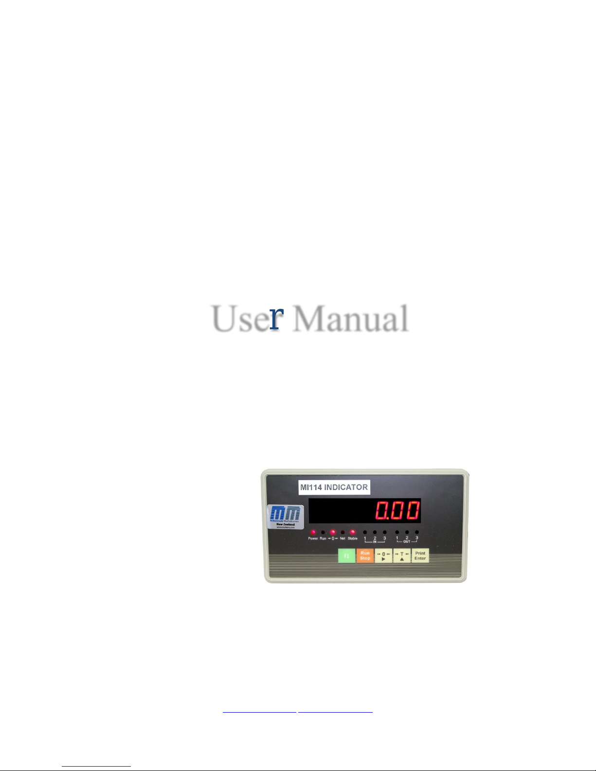
MI114
Batching Controller
User Manual
MI114R2
www.meltrons.com info@meltrons.com
Millennium Mechatronics Limited, PO Box 59187, Dr, Mangere, Manukau, Auckland 2151
Page 2

Page 3

MI114 User Manual
1
Contents
Chapter 1 Profile ---------------------------------------------------------------------------------------------------------------2
Chapter 2 Main Parameters ---------------------------------------------------------------------------------------------------3
Chapter 3 Installation, Interface and Data Format -------------------------------------------------------------------------4
I. Diagram of Front and Back Function Buttons of Indicator ------------------------------------------------------4
II. Connection of Load Cell and Indicator ----------------------------------------------------------------------------6
III. Input and Output Interface -----------------------------------------------------------------------------------------6
IV. Large-screen Display Interface-------------------------------------------------------------------------------------6
V. Serial Communication Interface ------------------------------------------------------------------------------------6
VI. Analog output --------------------------------------------------------------------------------------------------------7
VII. Print and Storage----------------------------------------------------------------------------------------------------8
Chapter 4 Parameter Setting and Calibration-------------------------------------------------------------------------------9
I. [SEt 0] Enquiry Parameter----------------------------------------------------------------------------------------9
II.【SEt 1】General Parameters --------------------------------------------------------------------------------- 11
III. [SEt 2] Control Parameters ----------------------------------------------------------------------------------- 12
IV. Record Print [SEt 3] ------------------------------------------------------------------------------------------- 16
V. Calibration ----------------------------------------------------------------------------------------------------------- 16
Chapter 5 Operating Instructions------------------------------------------------------------------------------------------- 18
I. Startup and zero setting upon startup ----------------------------------------------------------------------------- 18
II. Zero setting manually ---------------------------------------------------------------------------------------------- 18
III. Tare ------------------------------------------------------------------------------------------------------------------ 18
IV. Setting of date and time ------------------------------------------------------------------------------------------- 18
V. Startup/stop ---------------------------------------------------------------------------------------------------------- 18
VI. Peak holding-------------------------------------------------------------------------------------------------------- 18
VII. Input and output function---------------------------------------------------------------------------------------- 18
VIII. Inquiry of common parameters -------------------------------------------------------------------------------- 19
Chapter 6 Explanations of Control Procedure---------------------------------------------------------------------------- 20
I. Mode 0(additive mode with 1 batching material) ----------------------------------------------------------- 20
II. Mode 1(subtracting mode of 1 batching material) --------------------------------------------------------- 21
III. Mode 2(additive scale for two materials) ------------------------------------------------------------------ 24
IV. Mode 3(catchweighing mode) ------------------------------------------------------------------------------- 25
Annex 1 Error Message Prompt -------------------------------------------------------------------------------------------- 29
Annex 2 Large Screen Data Waveform Diagram and Format --------------------------------------------------------- 30
Annex 3 Serial Communication- Data Format of Command Response Mode ------------------------------------- 32
Page 4

MI114 User Manual
2
Chapter 1 Profile
MI114 uses an advanced delta-sigma A/D converter to achieve a higher speed and higher accuracy for batching
or packing systems. The MI114 single chip microprocessor and high-speed Σ-△A/D switch technology
performs conversions and displays weight, with the maximum conversion speed of up to 80 times/second. The
display can be easily connected to the strain gauge based load cells to form batching scales, packing scale,
weighing control systems etc , where high-speed and high precision weighing are required.
Main functions and features of MI114 weighing indicator:
1. Integration of additive scale, subtracting scale, catch weigher function, with 3-channel input of external
control and 3-channel control output;
2. Standard asynchronous serial communication interface (RS232 or RS422/485), with flexible communication
mode (continuous send and command response);
3. 0-20mA/4-20mA (or 0-5V/0-10V) DA precision analogue output, adjustable;
4. Upper and lower limit alarm output setting;
5. High-precision A/D conversion with readability up to 1/30000;
6. 5-point nonlinearity correction;
7. When changing indicator, re-calibration is not required; and you can use the new indicator with
parameters of earlier indicator;
8. Scoreboard output;
9. Flexible peak holding function;
10. Storage, inspection and deletion function of information such as summation of weighing data and
accumulated frequency etc.; power-off data protection is provided;
11. It can be connected to a serial printer to print weighing record, accumulated amounts or parameters;
manual or automatic print is optional;
12. It has tare function; when the automatic control is activated, automatic tare can be selected;
13. Configurable digital filtering of A/D data
14. Selection of printing unit: kg, t, g, lb;
16. Real-time clock, calendar, which is not affected by power off;
17. Factory defaults recovery function;
Page 5

MI114 User Manual
3
Chapter 2 Main Parameters
1. Type: MI114 weighing indicator
2. Accuracy: Class 3, n=3000
3. Input signal range: -19mV~ +19mV
4. Nonlinearity: ≤0.008%F.S
5. No. of connected load cell:
1- 8, 350Ω load cell
6. Power supply for load cell: DC:5V;350mA
7. Load cell wiring: 6 -wire
8. Display: Single-row 7-bit LED, character height 0.5”, and 11 status
indicating lamps
9. Division: 1/2/5/10/20/50/100 optional
10. Clock: Display real time and date.
11. Keyboard: Adopt 5 soft touch buttons
12. Scoreboard interface: Adopt serial output, 20mA constant current source signal.
13 Communication interface: Serial RS422/RS422/RS485, optional; (baud rate 1200~9600)
14. Print interface: Shared with serial port, and can be connected to serial printer.
15. Relay output: Capacity AC:220V; 0.5A
16. External input: Switch contact
17. Power supply: AC 110~230V, 50/60Hz 1A
18. Service temperature,
0~40℃;≤90%RH
19. Storage and transportation
temperature:
-20~50℃
20. External dimension: Housing: 150×76×85mm (width × height × depth)
Panel: 172×93×3mm (width × height × thickness)
21. Dead weight: Approximately 1.2kg
Page 6
MI114 User Manual
4
Chapter 3 Installation, Interface and Data Format
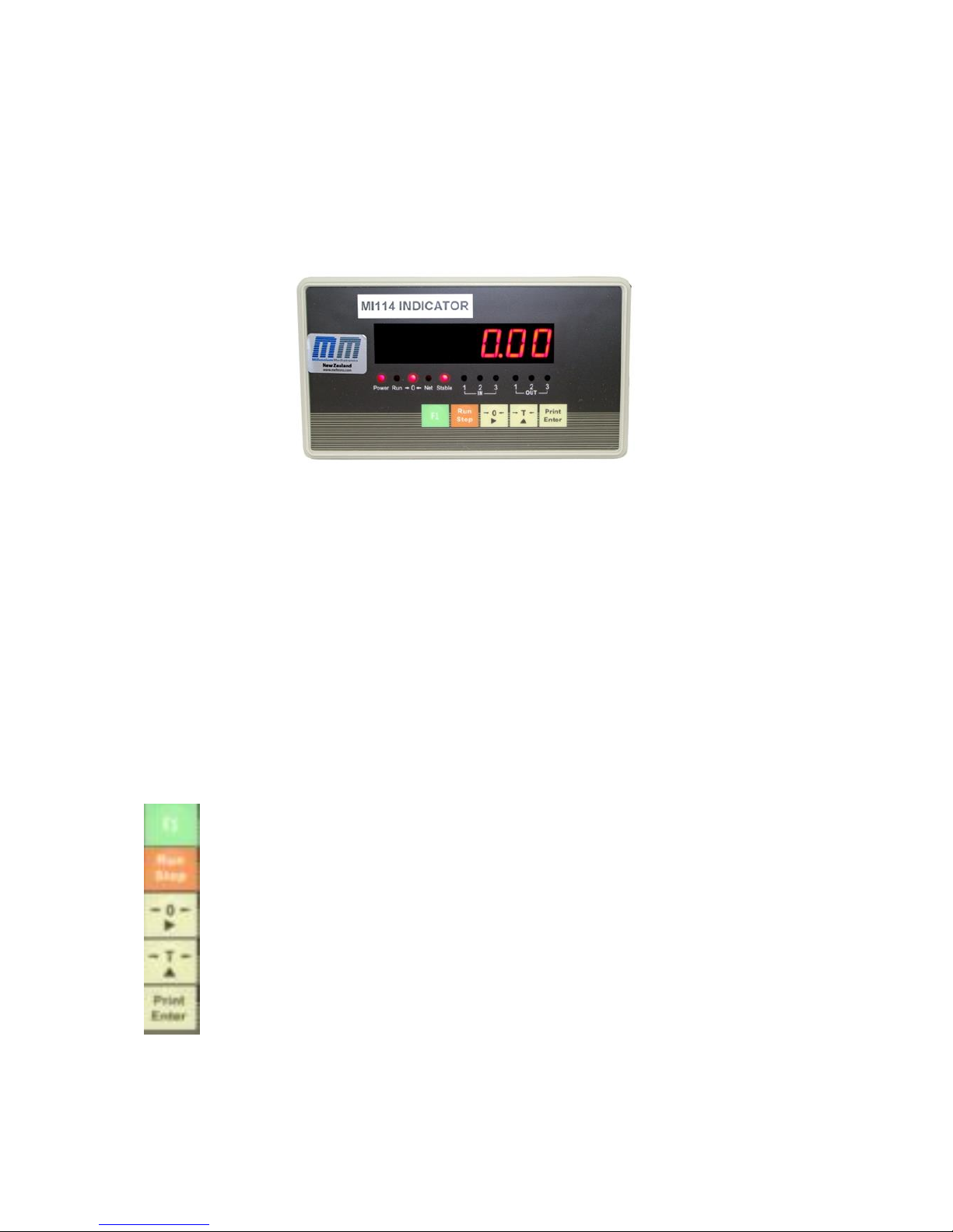
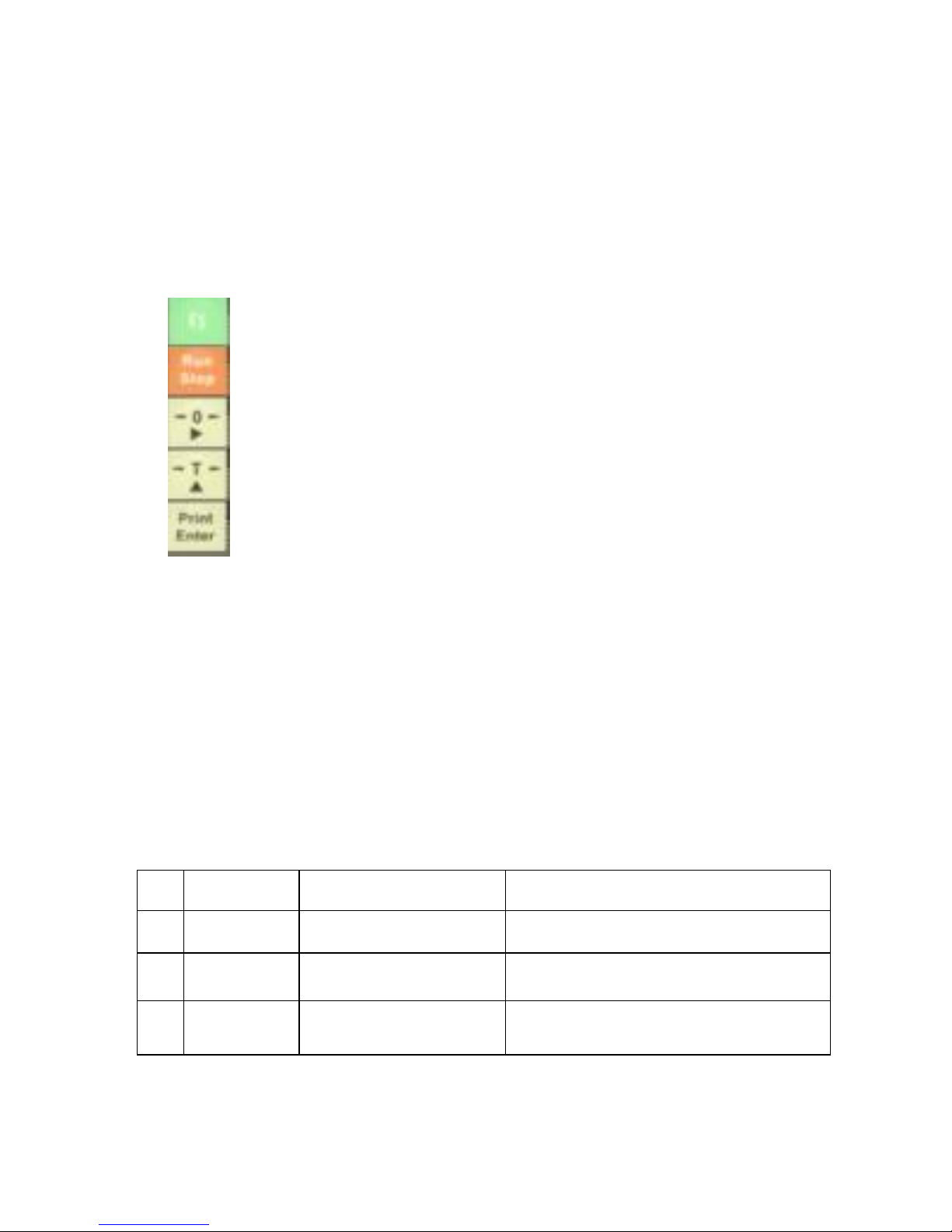
I. Diagram of Front and Back Function Buttons of Indicator
Figure 3-1 Diagram of Front Function Buttons
The meanings of the 11 indicating lamps on display panel are as follows (from left to right):
Power: Power supply indicating lamp
Run: Automatic operation status
>0<: Zero zone indication
Net: Net weight status
Stable: Stabilization status
IN: Three input indications (1, 2, 3 represents three inputs respectively)
OUT: Three output indications (1, 2, 3 represents three outputs respectively)
The five buttons on the display panel have the following functions:
Symbol
Button name
Meaning
[ F1 ] button
Press [F1] and [Operation] buttons simultaneously to examine the inner
code
[Run Stop]
button
It also serves as stop button. It is return button in parameter setting status
[-0-]
button
It is the shift key in parameter setting status.
[-T-] button
It is the “value increase” button in parameter setting
[Print Enter]button
It is the print button for displaying weighing value
Page 7
5
L N
GND
l10-230V 50/60Hz
01
02 03
+1
2V 11
12
13 OV
AC power
s
upply Output terminal
lnput terminal
CAL
ON OFF GND RxD TxD Y Z B A OP+
DP-
AO
I
A02
.
I
Calibration switch
Communication/Large-screen/
Analog output i nterface
EX+SEN+
SEN-EX-SlG+S I G-GND
Load cell interface
Figure
3-2
Diagram
or
Back Function Buttons
485/232
jumper
JP1
...
485/232
jumper
J
P2
.,
GND R:><.D l:><D
Bv yA
B Z '\'
Analog jumper J MS ., Ana
log jumper
JM3.,
Analog
jumper JM4 .,
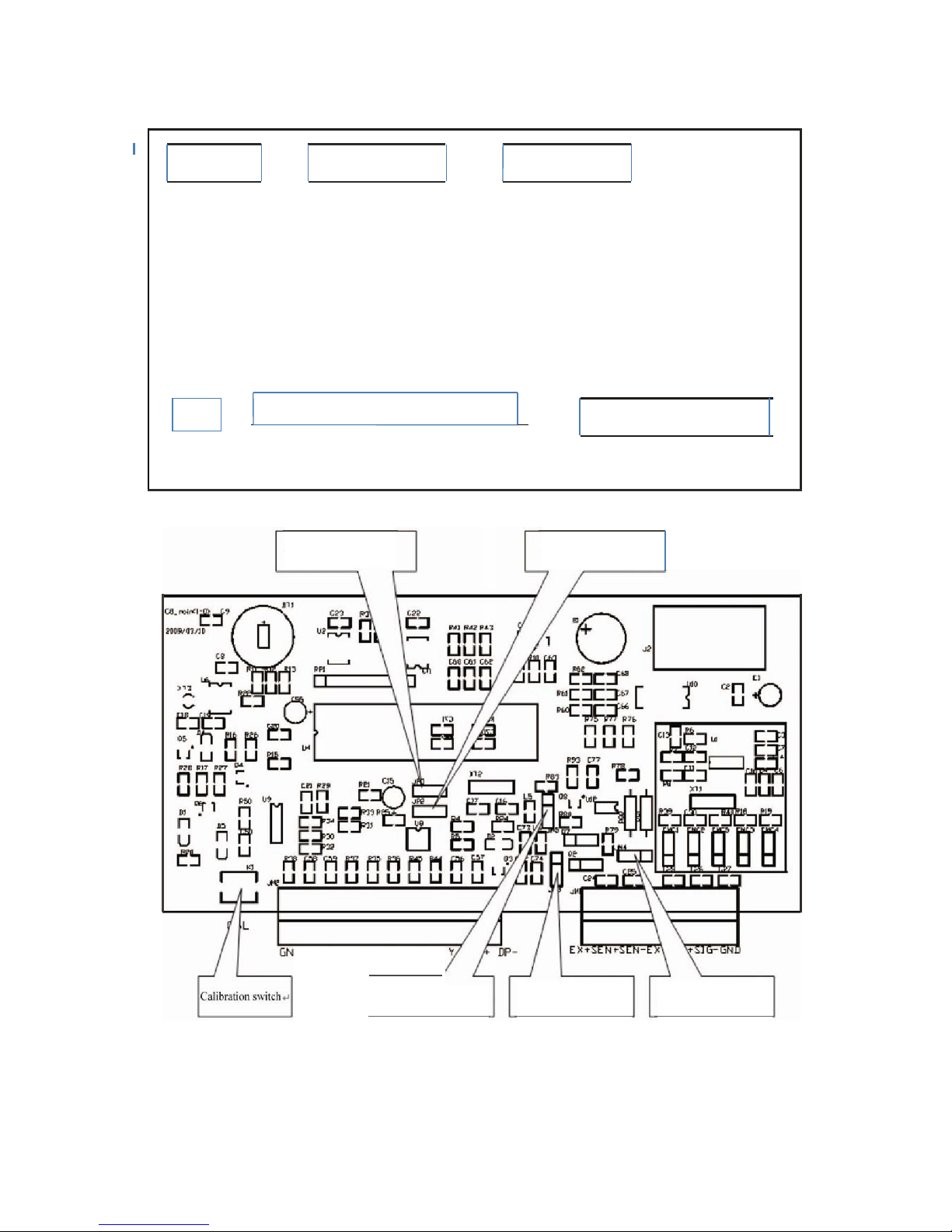
Figure 3 - 3 Diagram of Main Board Jumper and Calibration Switch
All interfaces in Figure 3-2 are described in detail below. P lease read the following detailed interface
description while referring to the interface position in Figure 3-2.
Page 8
6
MI114 Manual
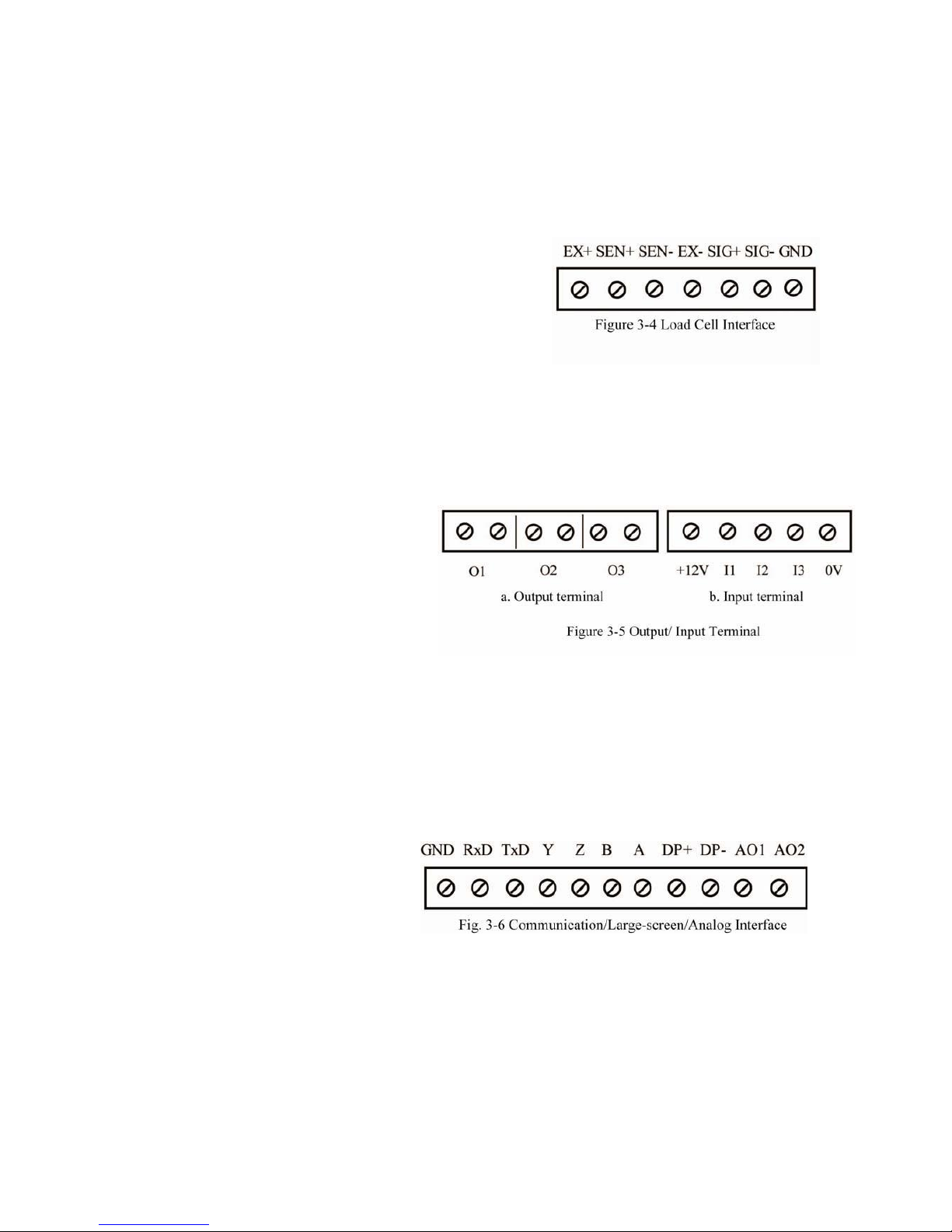
II. Connection of Load Cell and Indicator
The connection with load cell adopts the six wire system connection mode. Please refer to the interfaces in the
Diagram of Back Function Buttons, Figure 3-4. Detailed definitions are given below:
EX+: Positive load cell excitation
SEN+: Positive compensation
SEN-: Negative compensation
EX-: Negative load cell excitation
SIG+: Positive signal
SIG-: Negative signal
GND: Ground
Tip: If a 4 load cell cable is used to connect to MI114, the pins of “EX+” and “SEN+”, “SEN-” and “EX-
” in Figure 3-4 must be short-connected. Otherwise, the indicator cannot be calibrated and weigh
normally.
Ⅲ. Input and Output Interface
The indicator has three channels of optical
isolation input and three channels of relay
output. For interfaces, see Figure
3-5.
① The three outputs are connected to
the external system respectively according to
requirements. O1, O2, O3 terminals have
constant ON built-in relay, which can connect the controlled system directly to the two terminals of
corresponding interface.
Note: Switch contact; effective close control; contact capacity AC: 220V; 0.5A
② The access mode of three inputs is by connecting I1, I2, I3 with +12V, i.e. signal can be entered at the
input terminal. 0V terminal is prepared for customer’s special requirements.
The meaning of interface is different according to different modes. For detailed definition, please see
Chapter 5 Section 7 of this manual.
Note: The +12V terminal and 0V terminal cannot be short connected.
IV. Scoreboard Display Interface
For large-screen interface, see Figure 3-6:
DP+, DP- in the Figure are connected to
the large-screen. For the detailed
communication format, see Annex 2.
V. Serial Communication Interface
Serial communication interface uses RS232C (standard product). According to customer demand, the
RS485 interface can be selected through jumper (the output format is the same with RS232C). For the details
of the interface pin connection, see Table 3-1. For the jumper selection mode, see Table 3-2.
Page 9
7
MI114 Manual
Communication
interface
Jumper Selection
JP1 JP2
RS232C
(Factory defaults)
Left Left
RS485C
Right
Right
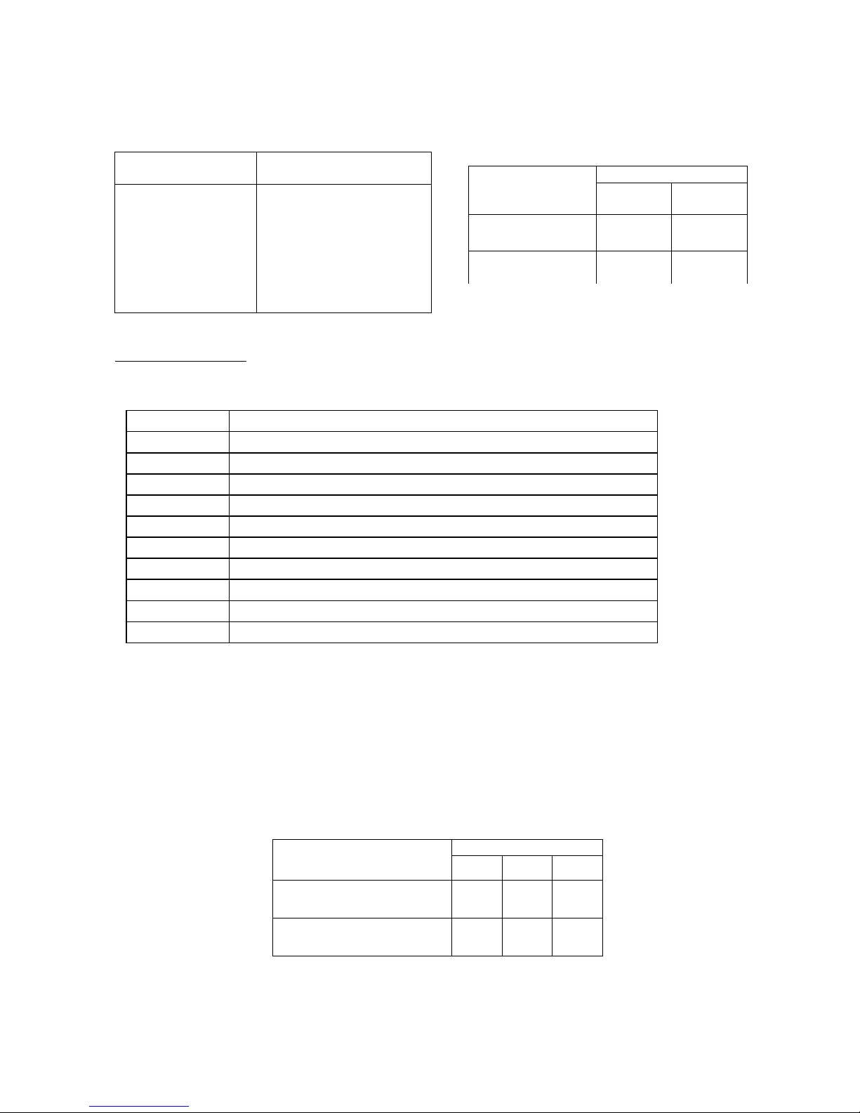
Table 3-1 Pin details Table 3-2 Selection of Communication
MI114 indicator can select “continuous send” or “command response”
mode:
Continuous send mode:
The transferred data is the current weight (gross weight or net weight) displayed on the indicator. Each
frame of data is composed of 12 groups of data. The format is as follows:
X
th
Byte
Contents and notes
1
02(XON) Start
2
+ or - Sign bit
3
Weighing data High-order bit
:
Weighing data :
:
Weighing data :
8
Weighing data Low-order bit
9
Decimal scale From right to left (0~4)
10
XOR check High four-bit
11
XOR check Low four-bit
12
03(X0FF) End
NOR=2⊕3⊕……8⊕9
2. Command response mode: For detailed format, please see Annex 3
VI. Analog output
MI114 indicator can choose 3 analog output modes: 0~5V, 0~10V voltage signal output and 4~20 mA
current signal output (It can be also be adjusted to 0~20 mA . The electric current loop adopts the internal
electrical power supply mode, the output mode is selected by jumper JM3~JM5 (See Figure 3-3) on the
main board. For the setting mode, see Table 3-3. The factory setting is 4~20 mA electric current loop. The
switch of analog output is controlled by the C bit of parameter [H ABC] under parameter [SET 1].
Table 3-3 Setting of Analog output
Analog output
Selection of jumper
JM3
JM4
JM5
4—20mA (Factory defaults)
Up
——
Down
0—5V
Down
Right
Up
232 Communication
485 Communication
GND: Grounded
RXD:
Receiving end of
indicator
TXD:
Sending end of
indicator
A: RXD+
receiving positive data
B: RXD-
receiving negative data
Z: TXD-
sending negative data
Y: TXD+
sending positive data
Page 10

8
MI114 Manual
0—10V
Down
Left
Up
Calibration method for analog output
The zero point value of analog output and full scale value are in direct proportion to corresponding DA
code (See Table 4-3, instructions of [SEt 1] parameter 12 and 13). The parameter 12 and parameter 13 can be
corrected by calculation according to the analog output error.
Note: At the mode of voltage output, short circuit of the analog output terminal is strictly
prohibited, and the load of 4-20mA electric current loop output cannot be disconnected, or otherwise
the analog output circuit may be damaged.
VII. Print and Storage
Print
The serial port communication RS232 connection mode is adopted. By means of selecting connection to
serial printer in indicator parameter Set 1, the weighing data can be printed through the serial port. Hand
print and automatic print are available, which are introduced below:
1. Hand print
Single print: In weighing status, press “Print/Enter” button to print the current time, date, net weight, tare
weight, accumulated frequency and accumulated weight.
Print record: At the mode of 0, 1, 2, all weighing records, including the time, date, net weight, tare weight,
accumulated frequency and accumulated weight for each weighing, can be stored and printed. For concrete
operations, see [Set 3].
2. Automatic print
After selecting printer and automatic print in parameter settings, information such as the current time,
date, net weight, tare weight, accumulated frequency and accumulated weight will be printed automatically
when a process is completed each time during the automatic control process.
Note: New prints cannot be made until it returns to zero after every print; if printer or hand peak
holding function is not selected, the hand print function is invalid; when communication in [Set 1] is not
selected or communication is selected but the serial printer is not selected, print is not valid; when the set baud
rate is not 9600, [Err P] will be prompted.
Storage
Storage is often used together with print, and is divided into hand storage and automatic storage.
Automatic storage should be enabled in parameter settings. Attention must be paid to several points during
storage:
1. Hand storage cannot be conducted in catch weighing mode.
2. The next storage cannot be executed until it returns to zero after each time of storage.
3. After the control mode (i.e. additive scale, subtracting scale, catch weigher) is changed, it needs to enter
the parameter setting 0 to eliminate the accumulated results, or otherwise an error may occur.
Page 11
9
MI114 Manual
Chapter 4 Parameter Setting and Calibration
If there is no special instruction for parameter setting, the button functions are as follows:
[F1] button: exit from parameter setting
[Operation] button: the current setting is not saved, and return to the previous parameter
[Zero setting] button: move the current flicker bit
[Tare] button: modify the current flickering value
[Enter] button: make sure to save the current parameter setting, and enter the next
parameter setting
Press [F1] button and [Zero setting] button simultaneously to enter parameter setting selection
interface. The setting catalogues are:
【SEt 0】 : enquiry parameter;
【SEt 1】 : general parameter;
【SEt 2】 : control parameter;
【SEt 3】 : print record (no such function in catch weighing mode)
[Note] Please note the instruction in remarks for each parameter. Part of parameters will only be
displayed under specific mode or conditions.
I. [SEt 0] Enquiry Parameter
Table 4-1 Non-Catch Weigher Mode
Para-
meter
Indicator
Display
Parameter Specification
Remarks
1 [n ****]
Accumulated frequency
It can only be inquired, but not changed.
2 [A******]
Accumulated weight
It can only be inquired, but not changed.
3 [dEL *]
Delete the selection of
accumulated frequency and
accumulated weight
0: no-operation
1: execute deletion operation
Page 12

10
MI114 Manual
4 [d**.**.**]
Current date setting
Press [Zero setting] button to move the current
flicker bit, press [Tare] button to modify parameter
value
5 [t**.**.**]
Current time setting
Press [Zero setting] button to move the current
flicker bit, press [Tare] button to modify parameter
value
6 [A ****]
Zero position calibration
Restricted parameter. The calibration switch must
be opened (turn the calibration switch CAL to the
left ON position) when changing, and input the
correct password.
Press [Enter] button to check the parameter
value one by one;
Before pressing [Tare] button to modify
parameter value, first enter the password
protection interface in Step 18!
These parameters can be modified only by entering
the correct password for one time.
When checking the parameters, the indicator will
return to weighing status after Step 16 is displayed.
7 [b ****]
CAL Coefficient
8 [C ****]
Nonlinear correction point 1
9 [d ****]
CAL Coefficient 2
(nonlinear correction)
10 [E ****]
Nonlinear correction point 2
11 [F ****]
CAL Coefficient 3
(nonlinear correction)
12 [L ****]
Nonlinear correction point 3
13 [H ****]
CAL Coefficient 4
(nonlinear correction)
14 [P ****]
Nonlinear correction point 4
15 [ t ****]
CAL Coefficient 5 (nonlinear
correction)
16 [ r ****]
Nonlinear correction point 5
17 [HF *]
Whether to restore factory
setting:
0: not restore; 1: restore
If recovery of factory setting is selected, it will
come into effect after re-startup, and the calibration
parameters will not be changed.
18
[PAS 000]
Password protection status
Password protection interface. Input the correct
password (111) and enter Step 6 to modify
parameters. If the password is wrong, it will return
to weighing status.
Table 4-2 Catch Weigher Mode
Para-
meter
Indicator
Display
Parameter Specification
Remarks
1 [n 1 ****]
Accumulated frequency of
Channel 1
It can only be inquired, but not changed.
2 [A******]
Accumulated weight of Channel
1
It can only be inquired, but not changed.
3 [n 2 ****]
Accumulated frequency of
Channel 2
It can only be inquired, but not changed.
4 [A******]
Accumulated weight of Channel
2
It can only be inquired, but not changed.
Page 13

11
MI114 Manual
5 [n 3 ****]
Accumulated frequency of
Channel 3
It can only be inquired, but not changed.
6
[A******]
Accumulated weight of Channel
3
It can only be inquired, but not changed.
7 [d**.**.**]
Setting of current date
The following parameters are same with the latter
part of Table 1.
II.【SEt 1】General Parameters
Table 4-3
Parameter
Indicator
Display
Parameter Specification
Remarks
1
[H ABC]
Hardware selection
A - Communication (0: communication is not
required, 1: communication is required)
B-Large-screen (0: large-screen is not required, 1:
large-screen is required)
C-Analog (0: analog is not required, 1: analog is
required)
For example: When
communication is required,
large-screen and analog are not
required, set it to [H 100].
Note: This setting will affect
the following display menu.
2
[n ABC]
Relevant Parameters of Zero Zone A-
zero setting range upon startup (0~5) B-
zero setting range by hand (0~5)
For example: if set the zero
setting range upon startup to
20%, the zero setting range by
hand to 4%, and the zero tracking
to 0.5e, it will be set to [n
421].
A,B
0 1 2 3 4
5
F .S%
0 2 4
10
20
100
C-zero tracking range (0~8)
When it is set to 0, the tracking function is closed.
For other values, see the following table:
C 1 2 3 4 5 6 7
8
(e
1
1.5 2 2.5 3 3.5
4
3
[FLt *]
AD Filtering Intensity (0~4)
The smaller the value is, the
faster the weight changes, but
the stability is worse; The bigger
the value is, the slower the
weight changes, but the stability
is better. The user should adjust
the parameter according to
requirements.
Value
0 1 2 3 4
Filtering
Intensity
weak
Compar
atively
weak
medium
Compar
atively
strong
Strong
4
[Adr **]
Communication Address of Indicator (01~26)
When several indicators send data to the same PC,
this communication address is required to
distinguish each of the indicators.
It won’t be displayed when
communication is not required.
5
[bt *]
Communication Baud Rate (0~4)
It won’t be displayed when
communication is not required.
BPS
0 1 2 3 4
BPS
600
1200
2400
4800
9600
Page 14

12
MI114 Manual
6
[tod *]
Communication Mode:
0-command response mode (Refer to Chapter 3);
1-continuous send mode
2-connect to serial printer
It won’t be displayed when
communication is not required.
7
[AtP *]
Automatic accumulated print:
0-automatic accumulation
1-automatic accumulation without print
2-automatic accumulation and automatic print
Accumulation and print conditions
should be set appropriately .
8
[Unit *]
Print Unit:
0-kg (kilogram)
1-g (gram)
2-t (ton)
3 – lb (lbs)
It is effective only when printing.
It won’t be displayed when
communication is not required.
9
[F *]
Peak Holding:
0-Peak holding is closed.
1-Peak holding is effective, and the holding will
be cancelled automatically after returning to zero.
2 - Peak holding is effective; press the button to
manually cancel holding.
Hand mode includes pressing the
input button and input terminal to
obtain input signal.
10 [AL*****]
The corresponding weight of analog output zero
point
Will not be displayed when analog
output is not required.
11 [A******]
The corresponding weight of analog output full
range
Will not be displayed when analog
output is not required.
12
[PL ***]
DA inner code (0-30000) when analog output is at
zero point
(Output 4-20mA signal is about 12520;
output 0-5V/0-10V is 0)
The zero point of analog output of
can be modified by editing this
code.
13
[PH ***]
DA inner code (30000-65535) when analog output
is at full range
(4-20mA output is about 62590;
0-5V/0-10V output is about 65200)
The full load point for calibration of
analog output can be modified by
editing this code.
14 [Prt *]
Whether to print this set parameter:
0: No.
1: Yes.
This item won’t be displayed when
there is no printer.
III. [SEt 2] Control Parameters
Table 4-4
Parameter
Indicator
Display
Parameter Specification
Remarks
1
[CP *]
Control Mode
0: 1 kind of additive mode of batching
1: 1 kind of subtraction mode of
batching
2: 2 kinds of additive mode of
batching
3:catchweighing mode
For work flows of all kinds of mode, see
Chapter 6.
2
[Pt 0]
Number of cycles
The number of control process (0 ~ 99, 0
stands for indefinite times)
Please select the corresponding parameter setting according to the set [Control Mode].
Page 15

13
MI114 Manual
Mode 0, 1 (Additive mode or subtraction mode for 1 kind of batching material)
3
[C ABCDE]
Advanced Control Parameters
A-quick or slow feed status
0: When quick feeding, only the
quick feed is opened.
1: When quick feeding, both the
quick and slow feed are opened
simultaneously.
B - automatic tare status before
feeding
0: no automatic tare
1: automatic tare
C -self-correction selection for lead
0: no correction
1: correction
D - out-of-tolerance treatment
selection
0: no treatment, the cycle
continues
1: wait for treatment until
qualified
E-material shortage gradual feed
0: no gradual feed
1: gradual feed
This parameter will change the control flow,
so generally no modification should be made.
Some parameters are invalid at subtraction
mode.
4
[A******]
Batching value
5
[b******]
Quick feed lead
6
[c******]
Slow feed lead
7
[d******]
Allowance
8
[L******]
Zero zone
1. When the indicator is discharging, if the net
weight is less than that of zero zone value, it
will be deemed as discharge completion;
2. The indicator print and accumulation
cannot be conducted until the gross weight is
greater than the zero zone value.
9
[t0 **]
0.0~9.9 seconds feed measurement
delay
To avoid weight misjudgment caused by
weight impact when starting.
10 [t1 **]
0.0~9.9 seconds delay of quick feed
over
11 [t2 **]
0.0~9.9 seconds delay of slow feed
over
12 [t3 **]
0.0~9.9 seconds gradual feed output
time
It won’t be displayed when there is no gradual
feed.
13 [t4 **]
0.0~9.9 seconds gradual feed interval
time
It won’t be displayed when there is no gradual
feed.
Page 16

14
MI114 Manual
14 [t5 **]
0.0~9.9 seconds time
Mode 0: discharge over delay
Mode 1: qualified output time
15 [t6 **]
0.0~9.9 seconds re-feed delay
16 [Prt *]
Whether to print this parameter:
0:No.
1: Yes.
It won’t be displayed when there is no printer.
Mode 2 (Additive mode for 2 kinds of batching)
3
[C ABCD]
Advanced Control Parameters
A - automatic tare status before
feeding
0: no automatic tare
1: automatic tare
B -self-correction selection for lead
0: no correction
1: correction
C -out-of-tolerance treatment
selection
0: no treatment, the cycle
continues
1: wait for treatment until qualified
D- material shortage gradual feed
0: no gradual feed
1: gradual feed
This parameter can change the control flow,
so it should be modified according to the
actual control needs.
4
[A******]
Material 1 quantitative value.
5
[b******]
Material 1 feed lead.
6
[C******]
Material 1 allowance.
7
[P******]
Material 2 quantitative value.
8
[d******]
Material 2 feed lead.
9
[t******]
Material 2 allowance.
10
[L******]
Zero zone
1. The gross weight is judged when the
indicator is discharging, if the net weight is
less than the zero zone value, it will be
deemed as discharge completion;
2. The indicator print and accumulation
cannot be conducted until the gross weight is
greater than the zero zone value.
11 [t0 **]
0.0~9.9 seconds feed measurement
delay
To avoid weight misjudgment caused by
weight impact during startup.
12 [t1 **]
0.0~9.9 seconds material 1 feed over
delay
Page 17

15
MI114 Manual
13 [t2 **]
0.0~9.9 seconds material 2 feed over
delay
14 [t3 **]
0.0~9.9 seconds gradual feed output
time
This item won’t be displayed when there is no
gradual feed.
15 [t4 **]
0.0~9.9 seconds gradual feed interval
time
It won’t be displayed when there is no gradual
feed.
16 [t5 **]
0.0 ~ 9.9 seconds discharge finish
delay
17 [t6 **]
0.0~9.9 seconds re-feed delay
18 [Prt *]
Whether to print this parameter:
0: No.
1: Yes.
It won’t be displayed when there is no printer.
Mode 3 (Catch Weighing Mode)
Parameter
Indicator
Display
Parameter Specification
Remarks
3
[FodE *]
Catch Weighing Mode:
0-Self-testing mode
1-External control mode
2-Upper and lower limit mode
Self-testing mode: When the weight is greater
than zero zone value, it starts catch weighing
automatically.
External control mode: Only when the
external control signal is triggered, the
indicator begins catch weighing.
Upper and lower limit mode: The real-time
upper, medium, lower limit relay output.
4
[H******]
Upper limit setting: Input a weight
value that is between zero and full
range.
When the weight value is smaller than the
lower limit, O1 is output;
When the weight value is between the lower
limit and upper limit, O2 is output;
When the weight value is greater than the
upper limit, O3 is output.
5
[L******]
Lower limit setting: Input a weight
value that is between zero and full
range.
6
[Lq*****]
Zero zone
1. Enter the next cycle only after sending out
the catch weighing signal and the indicator
weight is less than this value;
2. Enter t1 only when the indicator weight is
greater than this value at self-checking mode.
7
[t0 **]
Judgment Delay (0~9.9) Seconds:
At external control mode, data
calculation is conducted only after the
external control is triggered for t0
second;
At self-checking mode, data
calculation is conducted after the
weight leaves zero zone for t0 second.
8
[t1 **]
Calculation Time for Average
Weight (0~9.9) Seconds:
The indicator will accumulate,
average the weight within t1 after t0,
and the obtained value will serve as
catch weighing basis.
Page 18

16
MI114 Manual
9
[t2 **]
Calculation Delay (0~9.9) Seconds:
The indicator has no action within t2
after t1 is calculated, wait with delay.
10
[t3 **]
Signal Sending Time (0 ~ 9.9)
Seconds:
The indicator sends catchweighing
signal, with duration of t3 second.
11 [Prt *]
Whether to print this parameter:
0: No.
1: Yes.
It won’t be displayed when there is no printer.
★Please confirm H≥L during setting, or otherwise the indicator cannot work normally, and may cause
unexpected errors. The above time doesn’t take reaction time, such as relay action, into consideration.
IV. Record Print [SEt 3]
(This function is only effective at Mode 0, 1, 2)
Table 4-5
Parameter
Indicator
Display
Parameter Specification
Remarks
1
[n ***]
The sequence number of records to be printed
The sequence number of records
is corresponding to accumulated
frequency.
2
[Prt *]
Whether to print record:
0: No.
1: Yes.
It won’t be displayed when there
is no printer.
The form of printed record sheet is shown as Table 4-6:
Table 4-6
Date:
Feb 11, 2009
Time:
16:18:36
Net Weight:
5.00kg
Gross Weight:
0.00kg
Accumulated
Frequency:
0011
Accumulated
Weight:
115.00kg
V. Calibration
Turn the calibration switch CAL to the left ON position to open the calibration switch. Then press [F1]
button and [Enter] button simultaneously, the indicator displays [--CAL--], indicating entering calibration
status. Press [Enter] button to enter. For specific calibration parameter instructions and operation, refer to the
following table (* stands for the original set value):
Table 4-7
Step
Parameter
Display
Parameter Instruction
Operation Instruction
1
[E *]
Division: 1/2/5/10/20/50/100 optional
Press [Enter] after modifying parameters
2
[dC *]
Digits of decimal point (0-3)
Press [Enter] after modifying parameters
Page 19

17
MI114 Manual
3
[F******]
Full value (The limit set automatically is
full value plus 8 division)
Press [Enter] after modifying parameters
4
[r 0]
Save the original zero position:
0: S a v e the current zero position.
1: Skip over the current zero position
confirmation.
Input 0 to enter Step 5 (reco mmended),
Input1 to enter Step 7.
5
[noLoAd ]
Zero position confirmation
Confirm that the current weighing
platform has no load and the stability
light is ON, then press [Enter].
6
[*******]
Display the current AD code
Press [Enter] after the AD code is stable.
7
[AdLoAd1]
Load weights
Press [Enter] after the weight is loaded.
8
[*******]
Display the current AD code
Press [Enter] after the AD code is stable.
9
[ *******]
The weight of current loaded weights
Change to the weight value of current
weights, press [Enter] button to enter Step
12 and complete the calibration;
Change to the weight value of current
weights, press [F1] button to enter the
nonlinear correction flow of Step 10;
10 [AdLoAd* ]
th
Load weights, calibrate the weight of n
point (n<=5)
Press [Enter] to enter the next step after
weights are loaded.
11
[*******]
Display the current AD code
Press [Enter] to enter Step 9 cyclically
after the AD code is stable. (At most five
-point nonlinear correction can be
conducted)
12 [*******]
Display the current weight value
The calibration is finished. Return to
weighing status.
Please put the calibration switch at OFF position after calibration is finished
Page 20

18
MI114 Manual
Chapter 5 Operating Instructions
I. Startup and zero setting upon startup
After connecting to the power supply, the display performs self-check of strokes “0-9”, then shows the
version No.. After that, it enters into weighing mode. After startup, if the weight of empty scale deviates from
zero point, but remains within the zero range, the display will perform zero setting upon startup. If the weight is
out of the zero setting range, the display shows the weight based on the calibrated zero point. For information
on the zero setting, please refer to the setting of parameter B in the parameters 1:[n ABC] as described in
Chapter 1
【SEt 1】.
II. Zero setting manually
When the display value deviates from zero point, but remains within the range of zero setting manually,
and the light is steady, press the button【Zero setting】to make the display value reset to zero. The
zero point light will turn ON. For setting the zero range manually, refer to the setting of parameter A in the
parameters 1:[n ABC] as described in Chapter 1 【SEt 1】.
III. Tare
Under weighing status, when the displayed weight is a positive value and weighing is stable, press the
button 【Tare】to deduct the displayed value as tare. Then the displayed net weight is 0, with the net weight
indicator light ON.
IV. Setting of date and time
Set the date through the contents [d**.**.**] and the time through [t**.**.**] in parameters setting 【SEt
0】. Press the button【Zero setting】to change the flicker bit, and【Tare】to change the size. After completion
of setting, press the button【Enter】for setting of other parameters or exit from setting by pressing the button
【 F1 】.
V. Startup/stop
For startup or stop, press directly the button【Run】on key board, or input an impulse signal from the
“Startup” end of back panel. The indicator is ready to enter into control mode or exit from control mode.
VI. Peak holding
By means of setting the param eter [F *] in parameters【SEt 1, select the peaking holding mode:
0-peak holdings is off.
1-peak holding is valid, and it is cancelled automatically after zero setting.
2-peak holding is valid. Press the button【Enter】to enable peak holding; press the button【Enter】once
again to disable peak holding (under this status, the button【Enter】has no save manually/print function).
VII. Input and output function
The input and output has the following meanings under different modes:
Mode
Input
Output
I1
I2
I3
O1
O2
O3
Mode 0
startup/stop
feed
discharge
Quick feed
Slow feed
discharge
Mode 1
startup/stop
discharge
——
Quick discharge
Slow discharge
complete
Mode 2
startup/stop
feed
discharge
Feed material 1
Feed material 2
discharge
Mode 3
startup/stop
External
control
input
——
Net weight≤
lower limit
Lower limit < net
weight < upper
limit
Net weight ≥
upper limit
Page 21

19
MI114 Manual
Input and output test:
Press the button【F1】and【Run】simultaneously to enter internal code status. At this moment, if level
signal is given to the input end 1, 2 and 3, the output end 1, 2, and 3 will output corresponding signal, and the
light indicator on the front panel will turn on.
VIII. Inquiry of common parameters
Press the button【 F1 】under weighing mode to enquire the following parameters respectively:
Mode 0, 1:batching value, date, time
Mode 2 :batching value 1, batching value 2, date, time
Mode 3 :upper limit, lower limit, date, time
Page 22

20
MI114 Manual
Chapter 6 Explanations of Control Procedure
The four working modes of the indicator are explained in details as below:
I. Mode 0(additive mode with 1 batching material)
The double-speed batching of 1 kind of material mainly involves the following parameters: batching value
A1, quick feed lead b, slow feed lead C, allowance, zero value L. Please refer to the following figure for
understanding of the functions, meanings and time sequence of control input and output of various parameters
during the process:
Additive mode of 1 batching material:
Note: A—batching value; b—quick feed lead value; C—slow feed lead value; L—zero zone value. t0—
measurement delay;t1—quick feed over delay;t2—slow feed over delay;t3—gradual feed output
time;t4—interval time of gradual feed;t5—discharge over delay.
The schematic diagram of slow feed 1 shows the slow feed output when both the quick feed and slow
Page 23

21
MI114 Manual
feed are ON during quick feed process, and gradual feed exists.
The schematic diagram of slow feed 2 shows the slow feed output when only the quick feed is ON
during quick feed process, and without gradual feed.
The control procedure in the above diagram is consist of 4 processes including quick feed, slow feed,
gradual feed and discharge.
(1) Quick feed-- When the control procedure starts, the quick feed output gives out a signal, and the
corresponding O1 relay is closed. When the weight is added to the quick feed stop value A-b, the
quick feed output signal is cancelled, the corresponding O1 relay is switched off.
(2) Slow feed-- After a period of delay time t1 (quick feed over delay), the slow feed output gives out a
signal, and the corresponding O2 relay is closed. When weight is added to the slow feed stop value AC, the slow feed output signal is cancelled, the corresponding O2 relay is switched off. If the
parameter is set to both quick feed and slow feed ON, the slow feed output gives out a signal since
the beginning, and the corresponding O2 relay is closed until the weight reaches up to the slow feed
stop value A-C.
(3) Gradual feed-- If the parameter is set with gradual feed, the O2 relay corresponding to slow feed will
be closed for a period of t3, and switched off for a period of t4. Gradual feed is carried out through
such repeated cycle, until the weight reaches up to the allowance range of batching value, i.e. the
qualified area.
(4) Discharge-- Discharge output sends out a signal, and the corresponding O3 relay is closed. After the
weight is deducted from the value L in zero zone, the discharged is considered completed, which
corresponds to point M in the figure. At this moment, after another delay of t5, the discharge output
signal is cancelled, and the corresponding O3 relay is switched off. A complete control procedure is
finished.
Note: during the above process, if the slow feed lead is bigger than that of quick feed lead, i.e. C>b, then
the slow feed output won’t give out signal, and the corresponding O2 relay remains switched off. If no
gradual feed is set for parameters, the above gradual feed process (3) is not included. The turning off of
discharge should meet the conditions that the weight is less than zero zone value.
II. Mode 1(subtracting mode of 1 batching material)
Please refer to the following figure for understanding of the functions, meanings and time sequence of
control input and output of various parameters during the process:
Note: A—batching value; b—quick subtraction lead value; C—slow subtraction lead value;
t1—quick subtraction over delay;t2—slow subtraction over delay;t3—gradual feed output time;
t4—interval time of gradual feed;t5—discharge over delay
The schematic diagram of slow subtraction 1 shows the slow subtraction output when both the quick
subtraction and slow subtraction are ON during quick subtraction process, and gradual feed exists.
The schematic diagram of slow subtraction 2 shows the slow subtraction output when only the quick
Page 24

22
MI114 Manual
subtraction is ON during quick subtraction process, and without gradual feed.
The control procedure in the above diagram consists of 4 processes including quick subtraction, slow
subtraction, gradual feed allowance treatment and discharge.
(1) Quick subtraction -- When the control procedure starts, the quick subtraction output gives out a
signal, and the corresponding O1 relay is closed. When the weight is reduced to the quick
subtraction stop value A-b, the quick subtraction output signal is cancelled, the corresponding O1
relay is switched off.
(2) Slow subtraction -- After a period of delay time t1 (quick subtraction over delay), the slow
subtraction output gives out a signal, and the corresponding O2 relay is closed. When the weight is
reduced to the slow subtraction stop value A-C, the slow subtraction output signal is cancelled, the
corresponding O2 relay is switched off. If the parameter is set to both quick subtraction and slow
subtraction ON, the slow subtraction output gives out a signal since the beginning, and the
corresponding O2 relay is closed until the weight reaches up to the slow subtraction stop value A-C.
(3) Gradual feed -- If the parameter is set with gradual feed, the O2 relay corresponding to slow
subtraction will be closed for a period of t3, and switched off for a period of t4. Gradual feed is
carried out through such repeated cycle, until the weight reaches up to the allowance range of
batching value, i.e. the qualified area.
Page 25

23
MI114 Manual
(4) Discharge-- Discharge output sends out a signal, and the corresponding O3 relay is closed. After the
delay of t5, the discharge output signal is cancelled, and the corresponding O3 relay is switched off.
A complete control procedure is finished.
Note:
1. During the above process, if the slow subtraction lead value is bigger than the quick subtraction lead
value, i.e. C>b, the slow subtraction output won’t give out signal, and the corresponding O2 relay
maintains switched off. If no gradual feed is set for the parameters, the above gradual feed process
(3) is not included.
2. When the residual weight doesn’t reach to the batching value, the indicator stops subtraction, and
waits for feed signal. After receiving the feed signal, the indicator starts to feed material, and make
judgment to the weight during feeding process. When the batching value is obtained, material
feeding is stopped. At this moment, the weight can finish a subtraction cycle, then material
subtraction is continued. For example, if the batching value is 50Kg, when the remaining material in
the hopper is only 20kg, no subtraction will be performed until the hopper is added with material up
to 50Kg.
3. The discharge process in the subtracting scale can be used to remove the container loaded with
Page 26

24
MI114 Manual
material, just like a discharge process.
III. Mode 2(additive scale for two materials)
Note: A—batching value of material 1; b—lead value of material 1; P—batching value of material 2; d—lead
value of material 2; L—zero zone value.
t0—measurement delay;t1—feed over delay of material 1;t2—feed over delay of material 2;t3—gradual feed
output time; t4-interval time of gradual feed; t5-discharge over delay time.
The control procedure in the above diagram is composed of 5 processes including feed of material 1,
gradual feed out-of-allowance treatment of material 1, feed of material 2, gradual feed out-of-allowance
treatment of material 2 and discharge.
(1) Feed of material 1-- When the control procedure starts, the feed output of material 1 gives out a
signal, and the corresponding O1 relay is closed. When the weight is added to the feed stop value of
material 1 A-b, the feed output signal of material 1 is cancelled; the corresponding O1 relay is
switched off.
Page 27

25
MI114 Manual
(2) Gradual feed out-of-allowance treatment of material 1-- After the delay for a period of t1 (feed over
delay of material 1), if the parameter is set with gradual feed, the O2 relay corresponding to feed of
material 1 will be closed for a period of t3, and switched off for a period of t4. Gradual feed is
carried out through such repeated cycle, until the weight reaches up to the allowance range of
batching value of material 1, i.e. the qualified area.
(3) Feed of material 2-- The feed output of material 2 gives out a signal, and the corresponding O1 relay
is closed. When the weight is added to the feed stop value of material 2 P-d, the feed output signal of
material 2 is cancelled, the corresponding O1 relay is switched off
(4) Gradual feed out-of-allowance treatment of material 2 -- After the delay for a period of t2 (feed over
delay of material 2), if the parameter is set with gradual feed, the O2 relay corresponding to feed of
material 2 will be closed for a period of t3, and switched off for a period of t4. Gradual feed is
carried out through such repeated cycle, until the weight reaches up to the allowance range of
batching value of material 2, i.e. the qualified area.
(5) Discharge -- Discharge output sends out a signal, and the corresponding O3 relay is closed. After the
weight is less than the value L in zero zone, the discharged is considered completed, which
corresponds to point M in the figure. At this moment, after another delay of t5, the discharge output
signal is cancelled, and the corresponding O3 relay is switched off. A complete control procedure is
finished.
Note: If no gradual feed is set for parameters, the above gradual feed process (2), (4) is not included.
IV. Mode 3(catch weighing mode)
1. Self-check mode of catch weigher
Application examples:
Supposing a belt weigher is provided at the site, 3 kinds of cargoes of different weight 5Kg, 10Kg and
15Kg respectively need to be catch weighed through the belt user, which are transferred by the belt once every
10 seconds; the time for loading and unloading the weighing platform is about 2seconds, and the cargoes stay
on the platform for about 4 seconds, based on these conditions, we can make the following parameters setting
in 【SET--2】(2-digit decimal number is assumed to set during calibration). The cargoes less than 7.5kg are
sorted to channel 1, the cargoes between 7.5kg and12.5kg are sorted to channel 2, while those more than
12.5kg are sorted to channel 3.
Parameters
Indicator display
Parameters setting
Setting instructions
1
[CP *]
3
3 catch weighing modes are set hereof.
2
[Pt 0]
00
the times of control process (0~99,0 means
indefinite times)
Mode 3(catch weighing mode)
Page 28

26
MI114 Manual
Parameters
Indicator display
Parameters instructions
Remark
3
[FodE *]
0
Self-check mode: automatic catch weighing is
started when the weight is bigger than that in
zero zone
Upper and lower limit mode: real time upper
limit, intermediate limit and lower limit
relay output
4
[H******]
12.50
Set to the intermediate value of 2 cargoes to
facilitate catch weighing
5
[L******]
7.50
Set to the intermediate value of 2 cargoes to
facilitate catch weighing
6
[Lq*****]
4.00
A bigger value in zero zone to remove other
interference
7
[t0 **]
20
about 2 seconds for loading the weighing
platform
8
[t1 **]
40
about 4 seconds in staying on weighing
platform
9
[t2 **]
20
about 2 seconds waiting for the cargoes to be
unloaded from weighing platform
10 [t3 **]
20
send a channel signal with duration of 2
seconds
Please refer to the following diagram for control time sequence:
Schematic Diagram of Control Process 4
Page 29

27
MI114 Manual
Brief description of control process ( please understand in combination with the time sequence
diagram):
(1) The indicator is put into operation and judges if the weight is bigger than the value in zero zone. If so,
t0 delay is started, waiting for cargo to be loaded on the weighing platform.
(2) The time t0 is over, and starts to calculate the average weight of cargoes, with time duration of t1.
The value obtained from calculation serves as foundation for later catch weighing signals.
(3) The time t1 is over, t2 delay starts, waiting for the cargo to be unloaded from the weighing platform.
(4) The time t2 is over, and the catch weighing channel signal is sent, to make the cargo enter into the
corresponding channel. The time for sending channel signal is t3.
(5) The time t3 is over, and signal is sent, and the indicator judges once again if the weight returns to
zero zone. The next cycle can only begin when the weight stays within zero zone.
2. External mode of catch weigher
Application example:
It is assumed that a high speed catch weigher is used at site: the industrial control PLC together with this
indicator performs quick catch weighing to the cargo. PLC controls the transportation of cargo to the weighing
platform, and gives out a trigger signal to the indicator when it reaches there to make it calculate the weight.
The weight range of the qualified product of user is between 9.90Kg~10.10Kg. Channel signal is sent as per
weight, to make the PLC control and send to different channels. 1 cycle takes approximately 3-5 seconds.
The indicator and PLC should coordinate well. The parameters can be set in【SET--2】according to the
following table (2-digit decimal is assumed during calibration).
Param
eter
Indicator display
Parameter setting
Setting instruction
1
[CP *]
3
3 is set, catch weighing mode
2
[Pt 0]
00
Times of control procedure (0~99,0 for
indefinite times)
3
[FodE *]
1
External control mode: only when the
external control signal is triggered will the
indicator start the catch weighing
4
[H******]
10.10
Qualified upper limit
5
[L******]
9.90
Qualified lower limit
6
[Lq*****]
5.00
Zero area is big, other interference can be
removed
7
[t0 **]
02
The cargo is on the weighing platform when
receiving the trigger signal, no long delay is
required.
8
[t1 **]
20
2 seconds are sufficiently enough to calculate
the weight.
9
[t2 **]
00
After completing the calculation, PLC can be
notified at once to remove the cargo. No delay
is required.
10 [t3 **]
10
The channel signal with duration of 1 second
is sent to ensure the receipt by PLC.
Page 30

28
MI114 Manual
Please refer to following diagram for control of time sequence
Schematic Diagram of Control Process 5
Brief description of control process(In combination with the time sequence diagram)
(1) The indicators starts to run, waiting for trigger signal;
(2) The trigger signal is received, t0 delay occurs, waiting for cargo to be loaded stable.
(3) The time t0 is over; the indicator starts to calculate the average weight of cargo, with time duration
of t1. The value obtained from calculation serves as foundation for later catch weighing signal
(4) The time t1 is over, waiting for activation of t2.
(5) The time t2 is over, the channel signal for catch weighing is sent to make the cargo enter into
corresponding channels. The time for sending channel signal is t3.
(6) The time t3 is over, and the signal is sent and the indicator judges once again if the weight returns to
zero zone. The next cycle can’t be started only when the weight stays within zero zone
3. Upper and lower limit mode
After setting the upper and lower limit value, the instruction under operation will send real time the signal
at the output end according to the actual weight.
Page 31

29
MI114 Manual
Annex 1 Error Message Prompt
Err 01
Fail to meet tare requirements
Err 02
Fail to meet zero setting requirement
Err 03
The weight upon startup exceeds zero setting range
Err 04
Memory storage is full
Err 05
The input full value is 0 during calibration
Err 06
The calibrated loaded weight is too small
Err 07
The calibration switch is invalid
Err 08
Wrong input time or date
Err P
The baud rate setting does not meet requirements during printing
OL
The weight exceeds the full value
Page 32

30
MI114 Manual
Annex 2 Large Screen Data Waveform Diagram and Format
1. The large screen signal is the 20mA constant current loop signal, with binary code serial output, and
baud rate of 600. Every frame of data has 11 bits, including 1 start bit (0), 8 data bits (low-order bit in
front), 1 flag bit, and 1 stop bit (1).
2. A set of data is set every 100ms. Every set of data includes 3 frames of data, with meaning as follows:
Large Screen Data Frame Waveform Diagram
Page 33

31
MI114 Manual
The first frame data: flag bit is 0;
X:d0, d1, d2 are position of decimal point(0-3);
Y:d3-weight signal(1-negative;0-positive);
d4-gross/net weight(1-net weight;0-gross weight);
G17, G16:binary data;
The second frame data: flag bit is 0;
G15 ~ G8:binary data;
The third frame data: flag bit is 1;
G7 ~ G0:binary data;
G0 ~ G17: 18-bit binary code of weight in order from low to high
Page 34

32
MI114 Manual
Annex 3 Serial Communication-Data Format of Command
Response Mode
AD: indicator address(for example: A(ASCII code is41))
XH: check high four-bit
; XL: check low four-
bit. Note:
(1) The address is 1~26 when setting the indicator, and the corresponding address during communication
is A~Z;
(2) The command A~H is also sent in ASCII format.
Please refer to the following table in respect of the meaning of various letter command and
their communication format:
Command
Meaning
Format
Example
A
Send by PC
Handshake
02 AD 41 XH XL 03
02 41 41 30 30 03
Send by
indicator
Handshake
02 AD 61 XH XL 03
02 41 61 32 30 03
B
Send by PC
Read gross weight
02 AD 42 XH XL 03
02 41 42 30 33 03
Send by
indicator
Send gross weight
02 AD 62 ** ** ** ** ** **
** ** XH XL 03
02 41 62 2B 30 30 31 2E 30 30
30 32 37 03(1.000)
C
Send by PC
Ret net weight
02 AD 43 XH XL 03
02 41 43 30 32 03
Send by
indicator
Send net weight
02 AD 63 ** ** ** ** ** **
** ** XH XL 03
02 41 63 2B 30 30 30 2E 30 30
30 32 37 03(0.000)
D
Send by PC
Read tare
02 AD 44 XH XL 03
02 41 44 30 35 03
Send by
indicator
Send tare
02 AD 64 ** ** ** ** ** **
** ** XH XL 03
02 41 64 2B 30 30 31 2E 30 30
30 32 31 03(1.000)
E
Send by PC
Tare
02 AD 45 XH XL 03
02 41 45 30 34 03
Send by
indicator
Tare
02 AD 65 XH XL 03
02 41 65 32 34 03
F
Send by PC
Zero setting
02 AD 46 XH XL 03
02 41 46 30 37 03
Send by
indicator
Zero setting
Zero setting successful:
02 AD 66 XH XL 03
Zero setting conditions not
satisfied:
02 AD 69 XH XL 03
Zero setting successful:
02 41 66 32 37 03
Zero setting conditions not
satisfied:
02 41 69 32 38 03
G
Send by PC
Startup
02 AD 47 XH XL 03
02 41 47 30 36 03
Send by
indicator
Startup
02 AD 67 XH XL 03
02 41 67 32 36 03
H
Send by PC
Stop
02 AD 48 XH XL 03
02 41 48 30 39 03
Send by
indicator
Stop
02 AD 68 XH XL 03
02 41 68 32 39 03
 Loading...