

Page 1

FX312 & FX412 VERSION 2.0
MLR ELECTRONIQUE
1
Dear Customer,
Thank you for choosing the MLR FX312 GPS or the MLR FX412 DGPS Navigator. We are
confident it will give you many years of excellent service and you will enjoy exploring the
numerous functions available from this state of the
art GPS or DGPS.
For further information or technical help, please do not hesitate to contact your local dealer or
MLR Electronique in Vallet, who will be pleased to help you.
If you have chosen the FX312, you will be able to upgrade its accuracy by connecting it to the
MLR DF300 Differential Beacon Receiver, or by modifying it into a FX412. For more
information, contact your local dealer.
Yours sincerely,
Jean Pierre MAQUAIRE
C.E.O
Page 2

FX312 & FX412 VERSION 2.0
MLR ELECTRONIQUE
2
Page 3

FX312 & FX412 VERSION 2.0
MLR ELECTRONIQUE
3
ATTENTION: IMPORTANT NOTES
The United
States of America Department of Defence is responsible for the operation and
management of the GPS System. The accuracy is by “Selective Availability” which is
equivalent to plus or minus 100 metres.
The MLR FX312 high accuracy GPS or the MLR FX412 high accuracy DGPS is an AID TO
NAVIGATION ONLY and should not be used as a substitute for more traditional methods
of navigation.
When connecting your GPS or DGPS to other manufacturers equipment i.e. autopilots,
video plotters etc., you must still ensure a permanent watch is always kept as all
electronic instruments are designed to be an AID TO NAVIGATION ONLY.
MLR Electronique and their network of Distributors do not accept any responsibility for
any consequential losses resulting from the use of this dev
ice.
Page 4

FX312 & FX412 VERSION 2.0
MLR ELECTRONIQUE
4
Page 5

FX312 & FX412 VERSION 2.0
MLR ELECTRONIQUE
5
COM
-NO-
FX312 & FX412-02
GB
CONTENTS
A – PRESENTATION
................................................................................................................................................................
. 7
B – USING YOUR GPS
..............................................................................................................................................................
7
1 –
POSITION DISPLAY
..........................................................................................................................................................
7
2 –
NAVIGATION DISPLAY: SPEED AND COURSE OVER THE GROUND
.....................................................................
9
3 – GO TO
WAYPOINT
DISPLAYS
........................................................................................................................................
9
3.1. – ACTIVATE THE GOTO WAYPOINT FUNCTION
.....................................................................................................
9
3.2. – DEACTIVATE THE GOTO WAYPOINT FUNCTION
..............................................................................................12
3.3. – DISPLAY MODE SELECTION: DATA, COMPASS, 3D ROAD OR RADAR
...........................................................12
3.4. – CHANGING THE DESTINATION WAYPOINT
........................................................................................................14
3.5. – CREATING A NEW WAYPOINT
...............................................................................................................................14
3.6. – WAYPOINT ENTRY BY RANGE AND BEARING
.....................................................................................................15
3.7. – KEEPING YOUR WAYPOINT PERMANENTLY ACTIVE
........................................................................................16
3.8. – MODIFY A WAYPOINT
............................................................................................................................................17
3.9. – DELETE A WAYPOINT OR ALL OF THE WAYPOINTS
..........................................................................................18
3.10. – DISPLAY RANGE AND BEARING BETWEEN 2 WAYPOINTS
.............................................................................19
3.11. – WAYPOINT MEMORY ALLOCATION: USED AND FREE MEMORY
.................................................................. 20
4 –
GOTO ROUTE DISPLAY: FOLLOWING
A
ROUTE
......................................................................................................20
4.1. – ACTIVATE THE GOTO ROUTE FUNCTION
..........................................................................................................21
4.2. – DEACTIVATE THE GOTO ROUTE FUNCTION
.....................................................................................................22
4.3. – DISPLAY MODE SELECTION: DATA, COMPASS, 3D ROAD OR RADAR
...........................................................22
4.4. – CHANGING THE ROUTE IN USE
...........................................................................................................................23
4.5. – ENTER A NEW ROUTE
............................................................................................................................................23
4.6. – MODIFY A ROUTE
...................................................................................................................................................24
4.7. – DELETE A ROUTE OR ALL OF THE ROUTES
.......................................................................................................25
4.8. – ADVANCE TO THE NEXT WAYPOINT IN AN ACTIVE ROUTE
............................................................................25
4.9. – DISPLAY THE ROUTE DETAILS
.............................................................................................................................25
4.10. – ROUTE MEMORY : USED AND FREE MEMORY
................................................................................................26
5 –
PLOT
TER DISPLAY: VIEW YOUR TRACK AND CURRENT POSITION RELATIVE TO SURROUNDINGS
........27
5.1. – ACTIVATE THE HOME FUNCTION
........................................................................................................................27
5.2. – SELECT THE FULL SCREEN OR WINDOW MODE
...............................................................................................28
5.3. –
SELECTION OF WAYPOINT NAMES ON PLOTTER DISPLAY
.............................................................................28
5.4. – SELECTION OF THE TYPE OF INFORMATION DISPLAYED
..............................................................................29
5.5. – DISPLAY THE CHART OUTLINE
............................................................................................................................
30
5.6. – ENTER A CHAR
T OUTLINE
..................................................................................................................................... 30
5.7. – DELETE THE TRACK OR THE CHART OUTLINE
.................................................................................................32
5.8. – COPY THE TRACK OR THE CHART OUTLINE
.....................................................................................................33
5.9. – SELECT TRACKING INTERVAL BY DISTANCE
.....................................................................................................33
5.10. – TRACK AND CHART MEMORY: USED AND FREE MEMORY
...........................................................................34
5.11. – CHANGE THE ZOOM SCALE ON THE PLOTTER SCREEN
................................................................................34
5.12. – CURSOR MODE
......................................................................................................................................................35
5.13. – CENTER
THE PLOTTER SCREEN ON A WAYPOINT
..........................................................................................35
6 –
MAN OVER BOARD (MOB) AND MARK FUNCTIONS
..............................................................................................36
6.1. – MOB ACTIVATION
...................................................................................................................................................36
6.2. – MARK (EVENT / WAYPOINT) ACTIVATION
...........................................................................................................37
7 –
SIMULATOR FUNCTION
...............................................................................................................................................38
8 –
SATELLITES
....................................................................................................................................................................39
9 – TO
USE THE FX312 OR
THE FX412 IN DIFFERENTIAL MODE
.................................................................................39
9.1. – USING THE FX312 WITH THE MLR DF300 DIFF
ERENTIAL BEACON RECEIVER
...........................................39
9.2. – USING THE FX312 WITH OTHER MANUFACTURERS DGPS RECEIVERS
........................................................41
9.3. – USING THE FX412 IN DIFFERENTIAL MODE
......................................................................................................41
Page 6

FX312 & FX412 VERSION 2.0
MLR ELECTRONIQUE
6
10
–
USE OF DIGIPOINT TO ENTER WAYPOINTS,
ROUTES AND
CHART
OUTLINE
.................................................44
11
–
DGPS RECEPTION MESSAGES
................................................................................................................................... 44
12
–
SOFTWARE VERSION AND GPS YEAR OF YOUR RECEIVER
...............................................................................45
C – BEGINNERS GUIDE
.........................................................................................................................................................46
1 –
POWER ON/OFF
...............................................................................................................................................................46
2 –
SATELLITES
....................................................................................................................................................................47
3 –
CONTRAST AND BACKLIGHT ADJUSTMENT
...........................................................................................................48
4 –
GENERAL PROCEDURES USING THE KEYBOARD
..................................................................................................49
5 –
USE OF 'ARROWS' KEYS
AND ENTER
.........................................................................................................................51
6 –
ABBREVIATIONS AND SYMBOLS
...............................................................................................................................52
6.1. – ABBREVIATIONS AND SYMBOLS ON THE SCREEN
............................................................................................52
6.2. – MEASUREMENT ABBREVIATIONS
........................................................................................................................53
7 –
INITIALISATION AND CONFIGURATION OF YOUR GPS
........................................................................................53
7.1. – SYSTEM MENU
.........................................................................................................................................................54
7.2. – NAVIGATION MENU
................................................................................................................................................60
D – DESCRIPTION OF THE
EQUIPMENT AND S
PECIFICATIONS
.............................................................................67
1 –
CONTENTS OF FX312
.....................................................................................................................................................67
2 –
CONTENTS OF FX412
.....................................................................................................................................................67
3 –
COMMUN SPECIFICATIONS OF THE FX312 & FX412
................................................................................................67
4 –
PARTICULAR SPECI
FICATIONS OF THE FX412
.......................................................................................................69
E – INSTALLATION INSTRU
CTIONS
.................................................................................................................................70
1 –
RECEIVER CASE
.............................................................................................................................................................70
2 –
SITING THE ANTENNA
..................................................................................................................................................71
2.1.- FX312 ANTENNA
........................................................................................................................................................72
2.2.- FX412 ANTENNA
........................................................................................................................................................72
3 –
PROCEDURE FOR ELIMINATION OF INTERFERENCE (ONLY FOR FX412)
..........................................................74
3.1. – VERIFICATION OF DIFFERENTIAL SIGNAL RECEPTION
..................................................................................74
3.2. – DETECTION OF THE INTERFERENCE PRESENT
................................................................................................74
3.3. – DETECTION OF THE NATURE OF INTERFERENCE
...........................................................................................74
3.4. – SOLUTION TO INTERFERENCE ON THE POWER SUPPLY.
...............................................................................75
3.5. – SO
LUTION OF INTERFERENCE BY RADIATION
.................................................................................................75
3.6. – SOLUTION TO MECHANICAL INTERFERENCE
...................................................................................................75
MLR Electronique, 30 September 1999.
Page 7

FX312 & FX412 VERSION 2.0
MLR ELECTRONIQUE
7
YOUR USER’S MANUAL FX312 & FX412
This user manual applies to both units FX312 and FX412. For the FX412, you will find specific
instructions to install the receiver and its antenna as well as for its use in differential mode.
A – PRESENTATION
The MLR FX312 GPS is a radio–positioning receiver using signals from the NAVSTAR GPS
(Global Positioning System) satellite constellation. The MLR FX412 works with the GPS signals
and the signals from the DGPS radio-beacons. They offer simultaneously : high accuracy,
continuous coverage and world-
wide availability.
The FX312 and the FX412 display 5 function screens and 5 MENUS linked to these functions.
You have easy access to these screens with the new direct access concept (DIRECT
ACCESS™).
B –
USING YOUR GPS
1 – POSITION DISPLAY
IMPORTANT NOTE FOR FIRST TIME USERS : WE SUGGEST YOU BROWSE THROUGH
CHAPTER C, BEGINNERS GUIDE, AND CHAPTER E, ADVICE ON INSTALLATION.
Press the
Pos
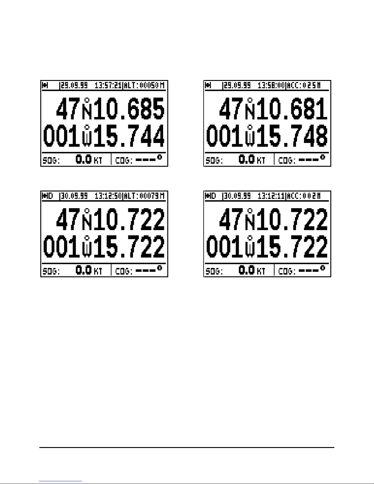
key to display the POSITION function. The geographical position of the vessel is
displayed in the centre of the screen in degrees, minutes, tenths, hundredths and thousandths
of minutes. The position can also be displayed in other types of co-ordinates (Lambert, Swiss
Grid, English Grid, Irish Grid etc.) which you may select from the SYSTEM MENU. The position
is updated every second when the symbol representing a satellite is displayed at the top left of
the screen.
You will find at the top of the screen:
- The symbol representing a satellite when the FX312 or FX412 calculates and
validates the displayed position.
- The letter D when the FX312 or FX412 calculates and validates the position in
differential mode.
-
The letter M when a message has been received from the Differential Station. To read
this message go to paragraph 11.
Page 8
FX312 & FX412 VERSION 2.0
MLR ELECTRONIQUE
8
- The date and the time. To display the local time, enter the time difference
between
local time and UTC in the SYSTEM MENU. In UK the time difference is +1 hour in
summer and 0 in winter.
- Your altitude, your accuracy (ACC) or no data, depending on your choice in the
SYSTEM MENU.
Your speed and course over ground are displ
ayed at the bottom of the screen.
When working in differential mode, the D letter is displayed in the top left of the screen.
Note 1: The accuracy displayed is also called ECP (Error Circular Probability), it is the radius of
the circle that contains 50% of the positions calculated by your GPS. The accuracy
automatically integrates working in differential mode.
Note 2: From the Navigation Menu you may select 2D, 3D or Auto mode. The altitude
measurement unit (i.e. metres or feet) can be selected
from the NAVIGATION MENU.
____________________
Page 9
FX312 & FX412 VERSION 2.0
MLR ELECTRONIQUE
9
2 – NAVIGATION DISPLAY: SPEED AND COURSE OVER THE GROUND
Press the
Nav
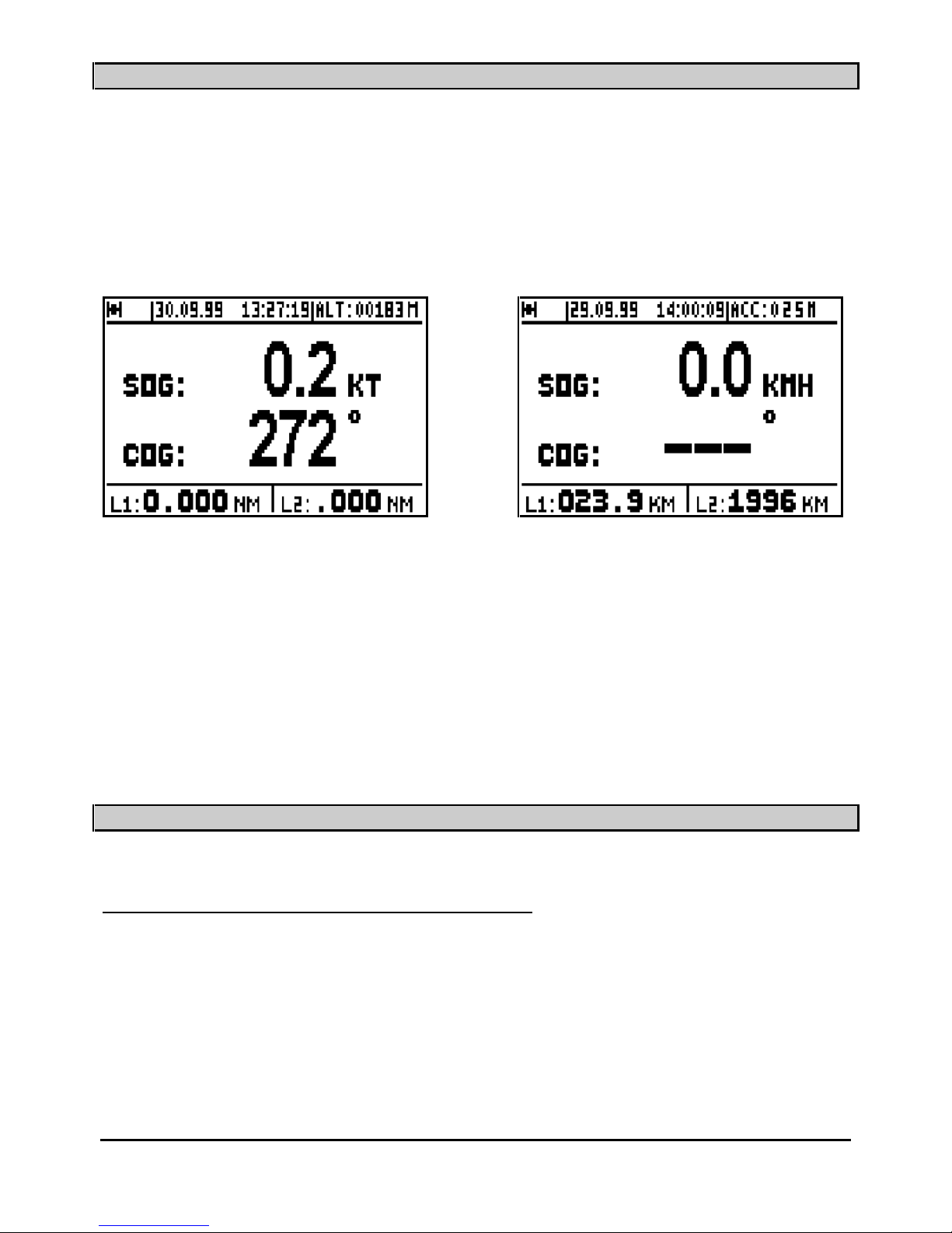
key to display the NAVIGATION function. The central part of the screen shows :
Speed Over the Ground
SOG
(in knots, kilometre/hours or in mile/hours) and Course Over the
Ground
COG
(in degrees) on the lower line.
Note: When the speed is zero, the course cannot be calculated and dashes are displayed.
Information displayed in the top part of this screen is identical to the POSITION
screen.
Two logs, L1 and L2 display the distances travelled (in the unit selected i.e. km, miles etc. from
the NAVIGATION MENU) in the lower part of the screen.
Note: From the NAVIGATION MENU you can reset to zero each log individually and con
figure
the following parameters: unit of distance, unit of altitude, 2D/3D/Auto mode, speed filter,
compass variation and alarms.
_____________________
3 – GO TO WAYPOINT DISPLAYS
3.1. – ACTIVATE THE GOTO WAYPOINT FUNCTION
Press the
GoTo
key. The
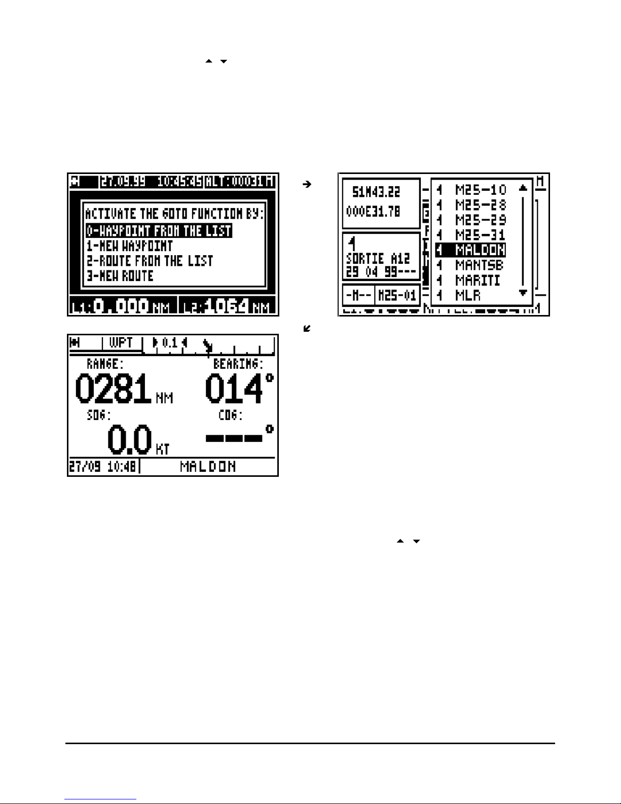
GOTO options are displayed unless a waypoint or a route has already
been selected; in which case you get the Data, Compass, 3D Road or Radar displays.
You now have the option of choosing a WAYPOINT FROM THE LIST, NEW WAYPOINT,
ROUTE FROM THE LIST or NEW
ROUTE.
Page 10
FX312 & FX412 VERSION 2.0
MLR ELECTRONIQUE
10
To select a waypoint from the list, press the 0 key (or select 0-WAYPOINT FROM THE LIST
and press
Enter
). Use the
arrow keys to move the cursor in the list and press
Enter
when
you have selected the desired waypoint.
Of course you can
Enter
a
new waypoint when the list of waypoints is empty (refer to paragraph
3.5 CREATE A NEW WAYPOINT)
You also have the option to activate a route from the list or to create a new route (see Chapter
4-
GOTO ROUTE).
Ti
p: For quick access to the required waypoint, use the alphanumeric keys. For example to
search for a waypoint starting with the letter R, push repeatedly on the 7
PRS
key to bring the
cursor on to the first waypoint starting with a R, then use the
arrow keys to select the
waypoint required.
Tip: The GOTO WAYPOINT function can also be activated from the WAYPOINT MENU by
pressing 0 - ACTIVATE.
In the COMPASS, 3D ROAD or RADAR mode in the GOTO WPT function you will see on the
left hand side seven lines of information, and on the right hand side a display which can be
either COMPASS, 3D ROAD or RADAR (see chapter B.3.3). At the bottom left of the screen,
the date and time are displayed and on the right, the name of the active destination waypoint. In
the
DATA mode, you will have the navigation information in large character as well as the cross
track error represented by a bargraph.
Page 11
FX312 & FX412 VERSION 2.0
MLR ELECTRONIQUE
11
Abbreviations – Navigation
RNG
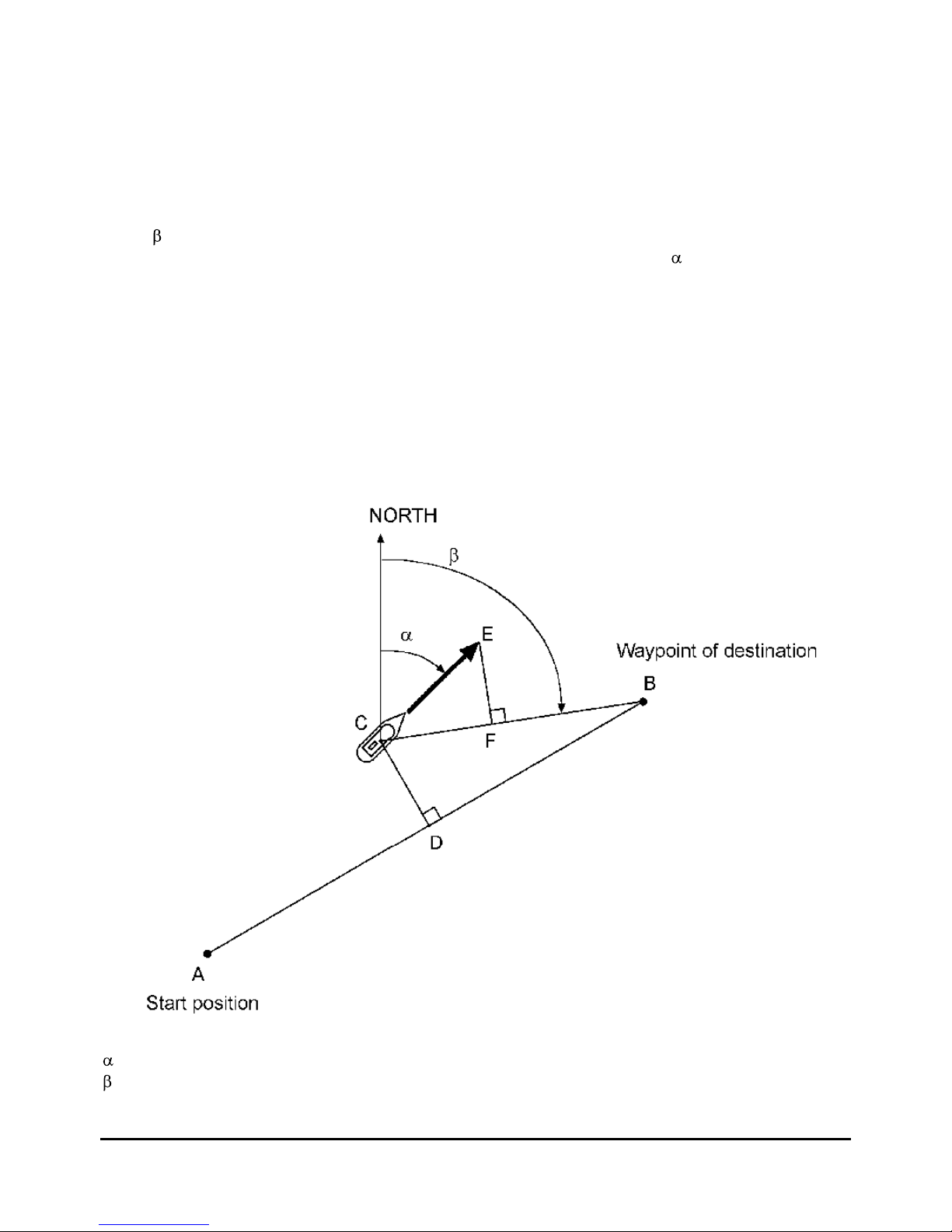
= Range between your position and the position of the destination waypoint in the select
ed
unit. C-B segment on the diagram below.
BRG
= Bearing, angle between your position and the position of the destination waypoint in
degrees. If your compass variation is zero, this angle is referenced in relation to true north.
Angle
on the diagram b
elow.
COG
= Course Over the Ground of the vessel in relation to North. Angle
.
XTE
= Cross Track Error, the error between the vessels course being steered and the actual
course you are taking. An arrow indicates if you must go on the left or to the right to reduce the
error. C-D segment.
SOG
= Speed Over the Ground. C-E vector.
VTD
= This is the Velocity To Destination. If this figure is positive you are heading towards your
target waypoint but if it is negative you are heading away from the waypoint
. C-F vector.
TTG = Time To Go to your destination waypoint. It is the VTD information that is used to
calculate the time to go.
ETA
= Estimated Time of Arrival to your destination waypoint. It is calculated using the TTG
information and current time.
= COURSE over the ground or route
= BEARING to the waypoint of destination
A -
B = direct line to the destination waypoint
Page 12
FX312 & FX412 VERSION 2.0
MLR ELECTRONIQUE
12
C -
B = Range to the destination waypoint
C -
E = Speed over the ground
C -
F = Velocity to destination
C -
D = Cross Track Error
XTE
Note: VTD, TTG and ETA are individually represented (compass, 3D road and radar).
Tip : To reach your destination waypoint using the shortest path, ensure that:
-
Your COG is equal to your BEARING.
- Your XTE must equal to zero.
-
Your Velocity to destination must be positive and equal your Speed over the ground.
Tip : When using the cross track error alarm (see Chapter C.7.2.8.C) you will be warned by the
alarm sound each time your cross track error becomes bigger than the limit you have
programmed.
3.2. – DEACTIVATE THE GOTO WAYPOINT FUNCTION
From the GOTO WAYPOINT function, press the
Menu
key then press key 1 (or select 1-
DEACTIVATE and press
Enter
) to deactivate the GOTO WAYPOINT function.
Tip: To activate a route when a waypoint is active. You must first deactivate the active waypoint
using the WAYPOINT MENU. You may then select a route from the GOTO Menu. Select Item 2
- ROUTE FROM THE LIST or Item 3 - NEW ROUTE to ACTIVATE THE GOTO ROUTE
function.
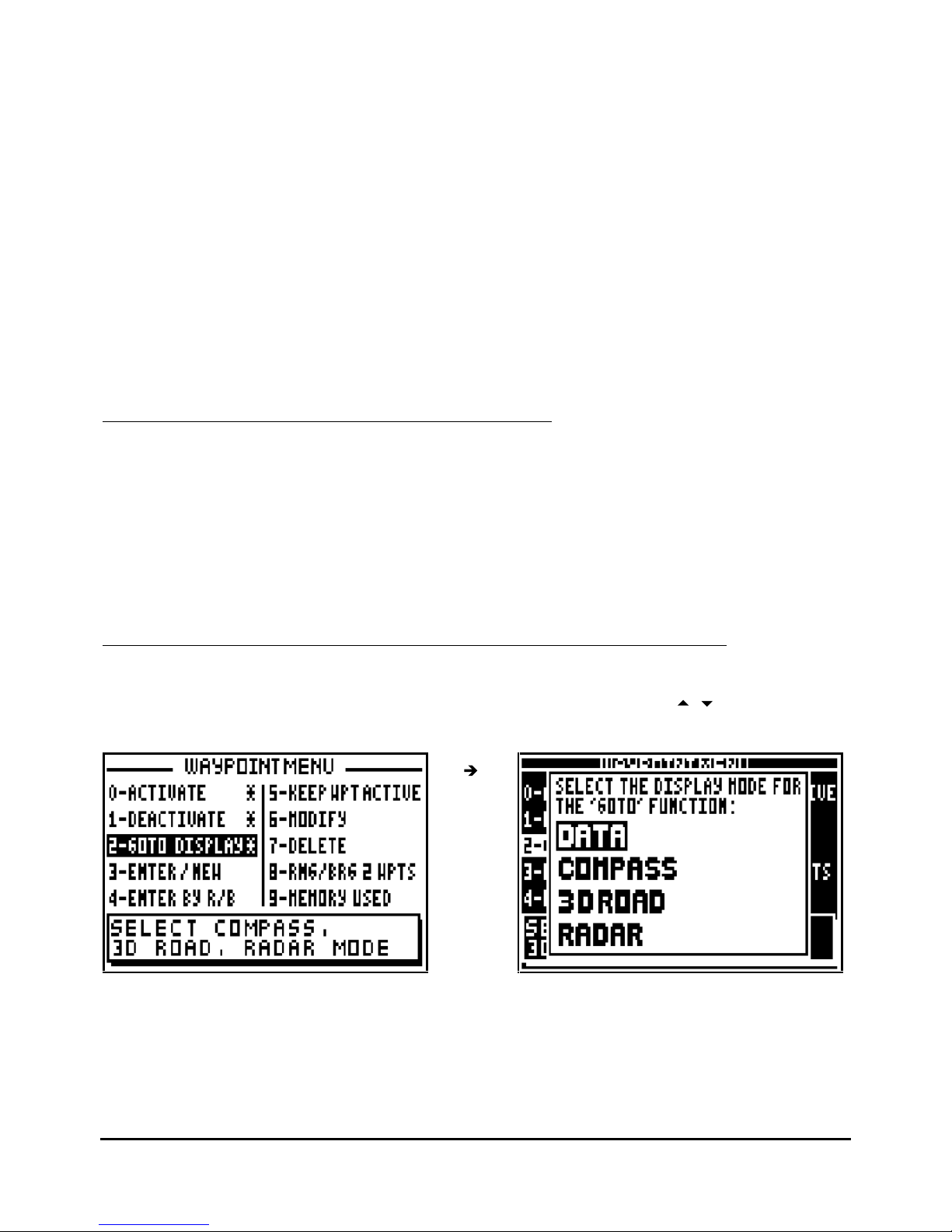
3.3. – DISPLAY MODE SELECTION: DATA, COMPAS
S, 3D ROAD OR RADAR
From the GOTO WAYPOINT function, press the
Menu
key then press key 2 (or select 2-
GOTO
DISPLAY and press
Enter
). Select the display mode required using the
arrow keys then
press
Enter
.
Note 1 : The indication of the cross track error (XTE) in the COMPASS, 3D ROAD and RADAR
screens gives you the distance C-D (see Chapter 3.1) and the letter R (Right) or letter L (Left)
indicates your position in comparison with the direct route. For instance XTE : R 0.05NM, you
are at the right of the route and at 0.05 nautic mile from the direct route. To correct your
direction, you have to go left.
Page 13
FX312 & FX412 VERSION 2.0
MLR ELECTRONIQUE
13
Note 2 : In the DATA and 3D ROAD screens, the cross track error is displayed by a bargraph.
This bargraph has 3 scales with automatic change, 0.1, 0.5, 2.5 in the chosen unit (kilometer,
nautic mile or miles). The scale is displayed either at the right or at the left of the arrow. Its value
corresponds to the distance between the 2 small arrows.
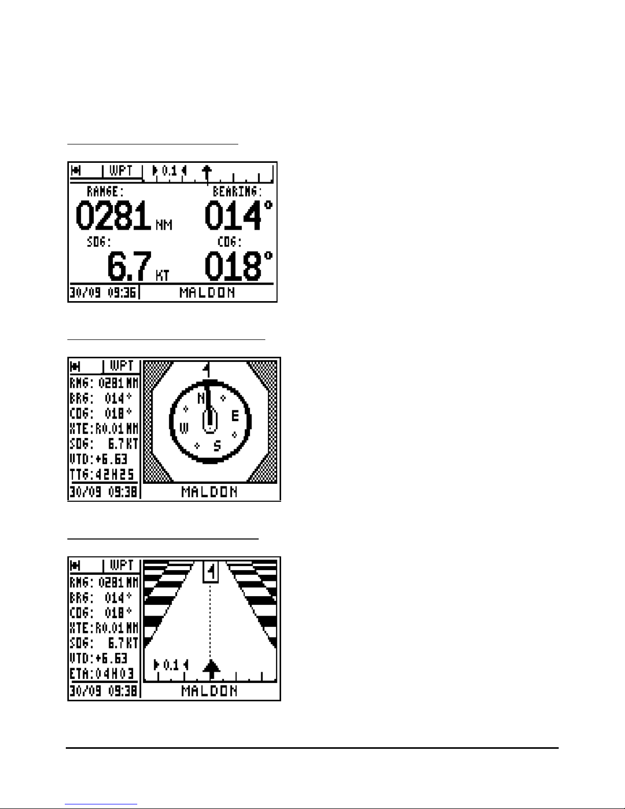
3.3.1 – GOTO WAYPOINT DATA
The arrow in the bargraph represents
your position according to your cross
track error. On the first line are displayed
the range and the bearing to the
waypoint. On the second line, the speed
and course over the ground.
To follow the direct course, sail in order
to keep the arrow in the vertical position
pointing up in the middle of the bargraph.
3.3.2 – GOTO WAYPOINT COMPASS
The compass pointer indicates the
vessel course, with the icon representing
the waypoint.
3.3.3 – GOTO WAYPOINT 3D ROAD
The arrow representing your vessel turns
according to your course and the bearing
to the waypoint. The arrow also moves
horizontally according to the amount of
cross track error. Every graduation is
equal to 0,25 KM or NM or MI. Keep the
arrow centered and pointing to the
top for
the most direct track to your waypoint.
The icon representing your destination
waypoint moves down the display as you
approach it.
Page 14
FX312 & FX412 VERSION 2.0
MLR ELECTRONIQUE
14
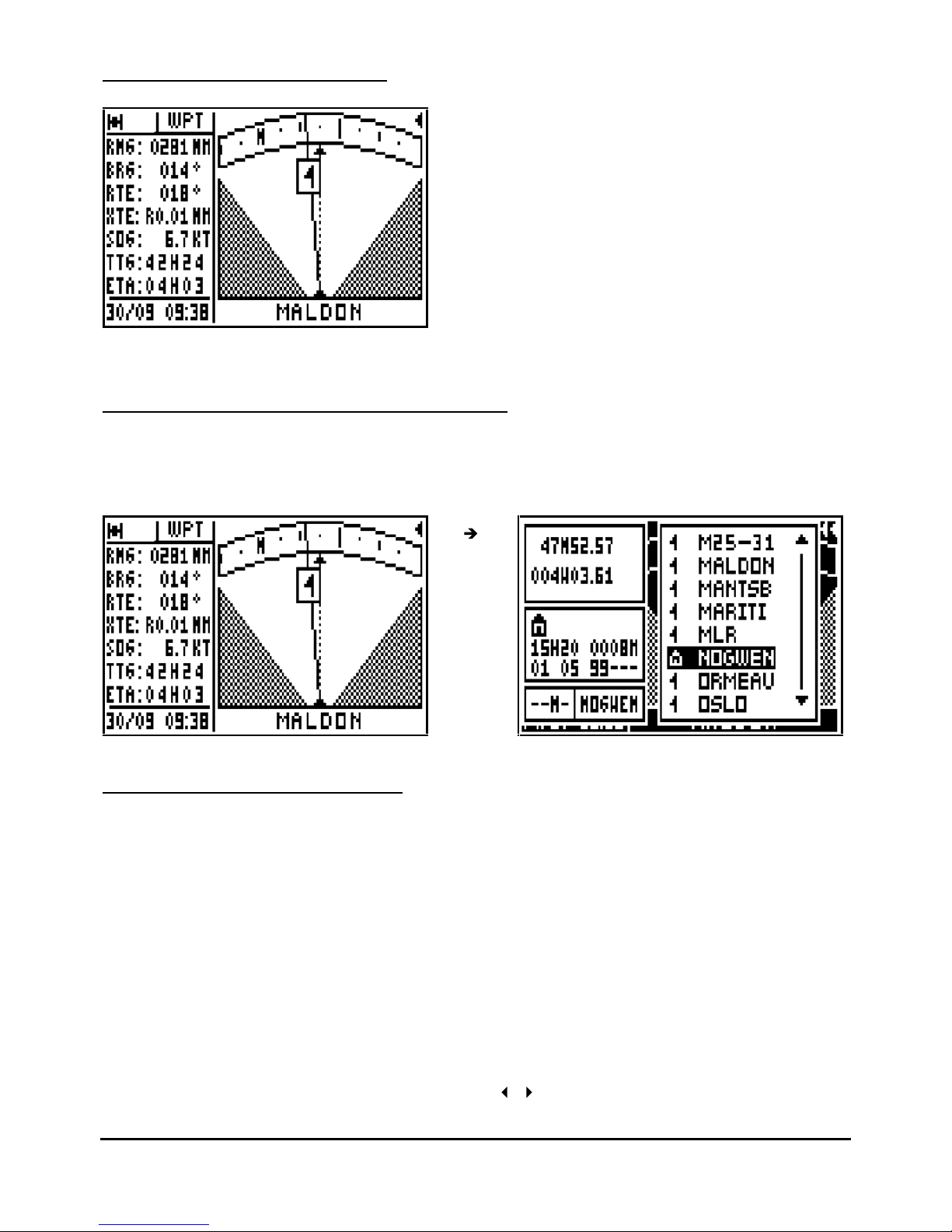
3.3.4 – GO TO WAYPOINT RADAR
Your course is represented by the dotted
line in the centre of the screen. A
con
tinuous line with the destination
waypoint icon is displayed to show the
bearing of the waypoint from your current
course. When the dotted line (vessel
course) is directly over the line with the
waypoint you are on course. If two
arrows are shown simultaneously this
indicates that the waypoint is outside of
the display area.
3.4. – CHANGING THE DESTINATION WAYPOINT
From the GOTO WAYPOINT function, press the 9
WXY List
key to display the list of your
waypoints, then select the new destination waypoint while proceeding in the same way as
paragraph B.3.1 ACTIVATE THE GOTO WAYPOINT FUNCTION.
3.5. – CREATING A NEW WAYPOINT
With your receiver you can create a new waypoint by following the instruction windows
displayed after pressing the
GoTo
key or fr
om the WAYPOINT MENU.
From the GOTO WAYPOINT function, press the
Menu
key then press key 3 (or select 3-
ENTER/NEW and press
Enter).
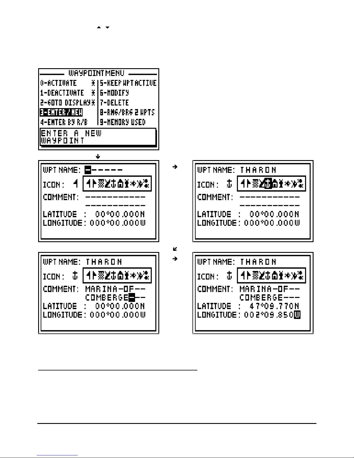
When the entered waypoint window is displayed, enter the NAME of the waypoint, select an
ICON for representation in the PLOTTER function, enter a COMMENT (optional), enter the
LATITUDE and the LONGITUDE then press
Enter
to validate your entry and store the new
waypoint.
Note: To enter a letter, press repeatedly the corresponding key (e.g. to enter a B, press 3 times
on key 2). Once the letter or the number is displayed, the cursor will advance automatically to
the next character. If you make a mistake, use the
arrow keys to move back or to advance
Page 15
FX312 & FX412 VERSION 2.0
MLR ELECTRONIQUE
15
the cursor. Use the
arrow keys to go back to the previous line or to go forward to the next
line.
Note: To select North or South for the latitude, use the key 6
MN_
for North and 7
PRS
for South.
To select East or West for the longitude, use the key
3
DEF
for East and
9
WXY
for West.
Tip: Do not
forget to press the
Enter
key to validate your entry and store your new waypoint.
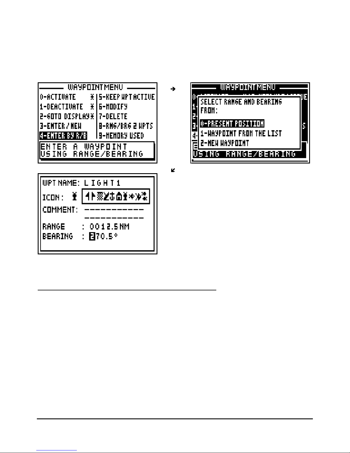
3.6. – WAYPOINT ENTRY BY RANGE AND BEARING
This function allows you to create a waypoint when you know its distance and bearing in relation
to a known position, another way
point or your position.
Page 16
FX312 & FX412 VERSION 2.0
MLR ELECTRONIQUE
16
From the GOTO WAYPOINT function, press the
Menu
key then press the key 4 (or select 4–
ENTER BY R/B and press
Enter
) to display the options window. Select your reference position
from the options using the 0, 1 or 2 keys and press
the
Enter
key. Follow the procedure
described in paragraph 3.5 - CREATING A NEW WAYPOINT for entering the name of the
waypoint, selecting an icon and writing a comment (optional). Now enter the distance and
bearing between the reference position and the waypoint position and press
Enter
to validate.
The receiver now calculates and stores the position of the waypoint
Tip: Do not forget to press the
Enter
key to validate your entry and store your new waypoint.
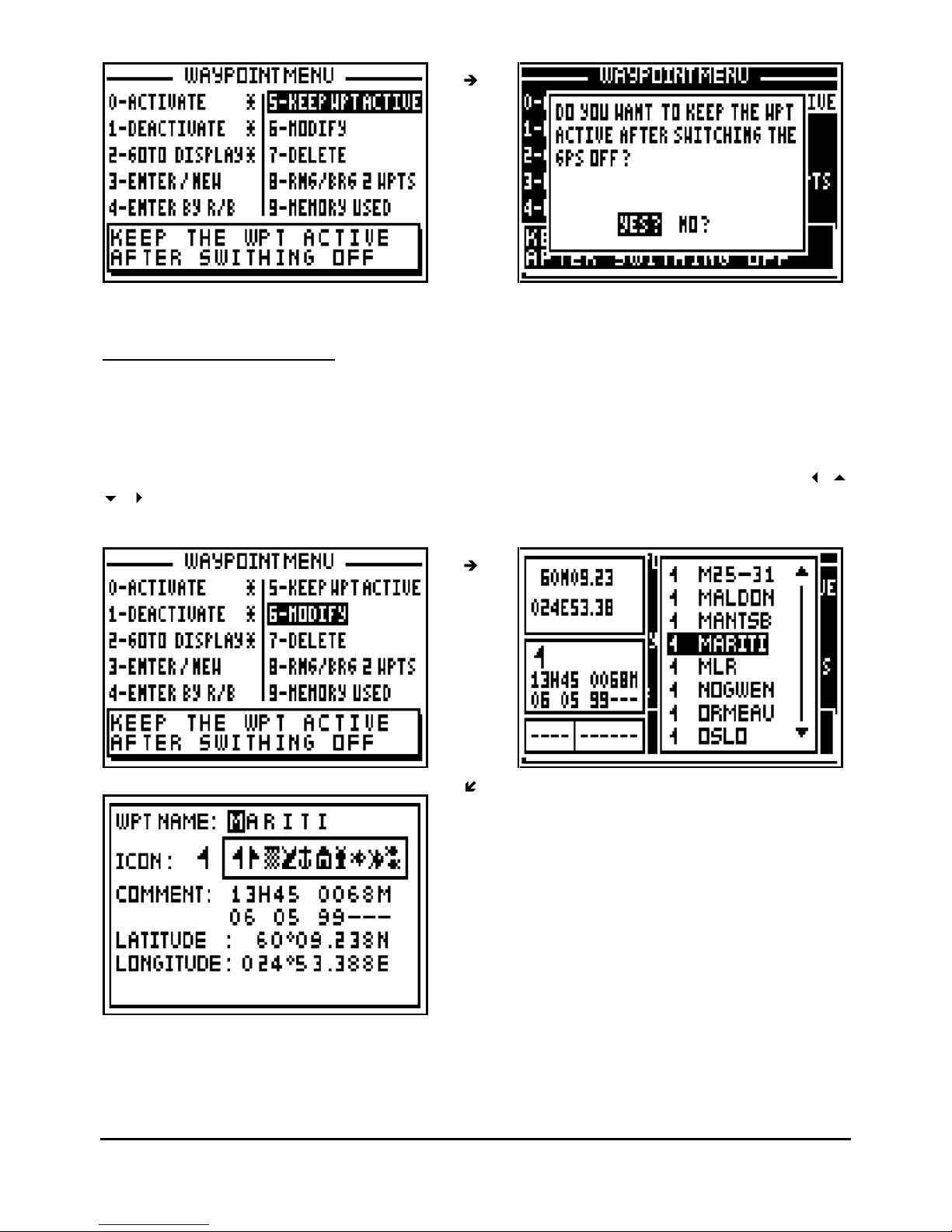
3.7. – KEEPING YOUR WAYPOINT
PERMANENTLY ACTIVE
You have the option of keeping your waypoint active after switching off your GPS. If a waypoint
is active before you switch off the GPS, it will be active again when you switch it on.
From the GOTO WAYPOINT function, press the
Menu
key then press the key 5 (or select 5-
KEEP WPT ACTIVE and press
Enter)
to display the option window. Select YES to keep the
waypoint active and press the
Enter
key.
Page 17
FX312 & FX412 VERSION 2.0
MLR ELECTRONIQUE
17
Note : By default, the waypoint is kept active.
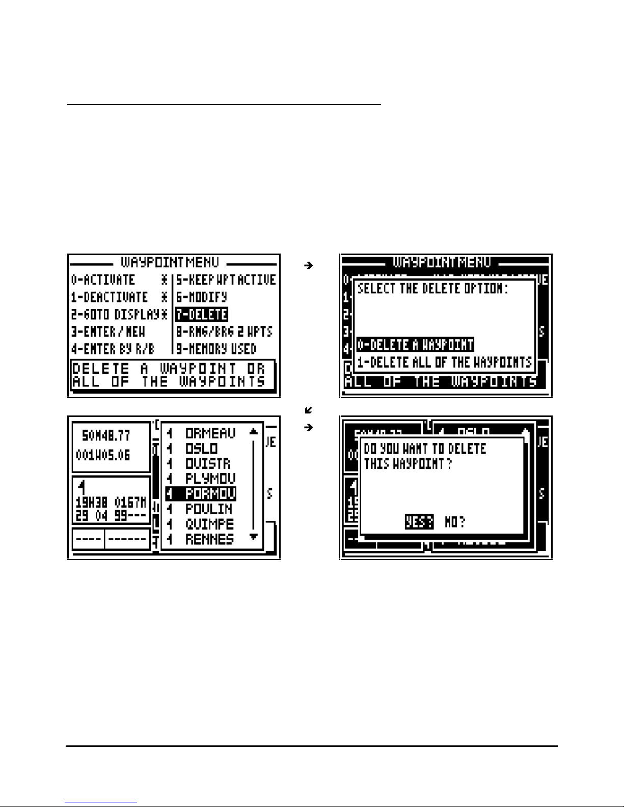
3.8. – MODIFY A WAYPOINT
From the GOTO WAYPOINT function, press the
Menu
key then press the key 6 (or select 6-
MODIFY and press
Enter
), your waypoint list will be displayed. Select the waypoint you wish to
modify, press
Enter
.
The identical option window to the ENTER/NEW waypoint function is displayed. Use the
arrow keys to move your cursor and to make the desired modifications. Once the
modification is made, press
Enter
to store your changes.
Tip: Do not forget to press the
Enter
key to validate your modificat
ions and store them.
Page 18
FX312 & FX412 VERSION 2.0
MLR ELECTRONIQUE
18
Note : In some cases, it is not possible to modify a waypoint, for instance when the waypoint
selected is already active or of it belongs to the active route,…
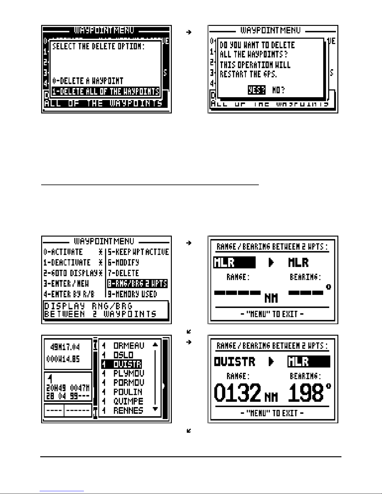
3.9. – DELETE A WAYPOINT OR ALL OF THE WAYPOINTS
From the GOTO WAYPOINT function, press the
Menu
key then press key 7 (or select 7-
DELETE and press
Enter
).
To delete only one waypoint press key 0 (or select 0-DELETE A WAYPOINT and press
Enter
),
the list of your waypoints is displayed. Select the waypoint to be deleted, press
Enter
then
select YES? and confirm by pressing
Enter
.
Note : It is not possible to delete the active waypoint or a waypoint which belongs to one or
several routes.
Tip: If you do not want to delete the waypoint, press the
Pos, Nav, G
oTo, Plot
or
Menu
function
keys to cancel the operation.
To delete all your waypoints, press key 1 (or select 1-DELETE ALL OF THE WAYPOINTS and
press
Enter
) select
YES?
then confirm by pressing
Enter
.
Page 19
FX312 & FX412 VERSION 2.0
MLR ELECTRONIQUE
19
Tip: If you do not want to delete all your waypoints, select
NO?
and press
Enter
or press the
Pos, Nav, GoTo, Plot
or
Menu
function keys to cancel the operation.
Note: Once all your waypoints are deleted, it will not be possible to reinstate them, it will
also erase all your routes.
3.10. – DISPLAY
RANGE AND BEARING BETWEEN 2 WAYPOINTS
From the GOTO WAYPOINT function, press the
Menu
key then press the key 8 (or select 8-
RNG/BRG 2 WPTS and press
Enter
), then press the 9
WXY
List key or the
Enter
key to display
the list of your waypoints. Select the first waypoint and press
Enter
, follow the same procedure
for the second waypoint.
Page 20
FX312 & FX412 VERSION 2.0
MLR ELECTRONIQUE
20
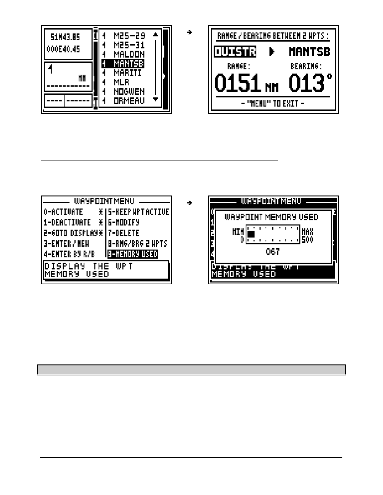
Note : The range from the waypoint OUISTR to the waypoint MANTSB is 151 MN and the
bearing to go from OUISTR to MANTSB is 13°.
3.11. – WAYP
OINT MEMORY ALLOCATION: USED AND FREE MEMORY
From the GOTO WAYPOINT function, press the
Menu
key then press the key 9 (or select 9-
MEMORY USED and press
Enter).
Note: The capacity of the memory is 500 waypoints.
____________________
4 – GOTO ROUTE DISPLAY: FOLLOWING A ROUTE
The GOTO ROUTE function is similar in operation to the GOTO WAYPOINT function, may we
suggest you to read paragraph B.3 for additional information. A route is a number of waypoints
linked together in any sequence
chosen by the user.
Page 21
FX312 & FX412 VERSION 2.0
MLR ELECTRONIQUE
21
4.1. – ACTIVATE THE GOTO ROUTE FUNCTION
Press the
GoTo
key. Select either GOTO RTE or GOTO WPT, this will activate the selected
function. Select a route from the list or create a new route. You also have the option to activate
a waypo
int from the list or create a new waypoint (see the chapter GOTO WAYPOINT).
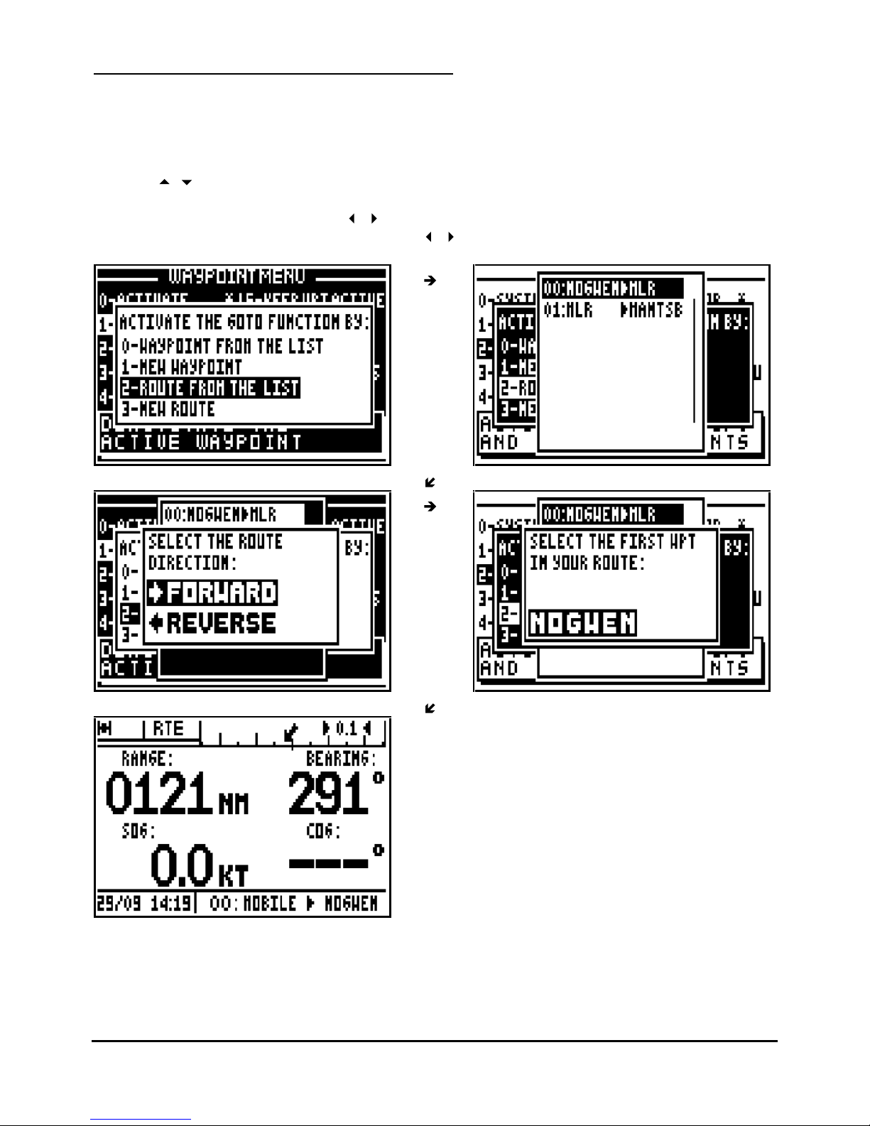
To select a route from the list press key 2 (or select 2
-ROUTE FROM LIST and press
Enter
)
Use the
arrow keys to move the cursor through the list and to select the desired route
,
press
Enter
.
Select the route direction using the
arrow keys and press Enter.
Select the first waypoint in the route using the
arrow keys and press
Enter.
Note: The GOTO ROUTE function can also be activated from the ROUTE MENU by choosing 0
-
ACTIVATE.
Page 22
FX312 & FX412 VERSION 2.0
MLR ELECTRONIQUE
22
The displayed information and the representation diagrams are identical to those of the GOTO
WAYPOINT function. The only difference is located on the bottom right of the screen where the
name of the waypoint is replaced by the number of the active route along with the departure
waypoint name and the next waypoint name in the route. The advance to the next waypoint is
selected using the Arrival Alarm function, when the waypoint alarm distance has been reached
the nex
t waypoint is automatically selected.
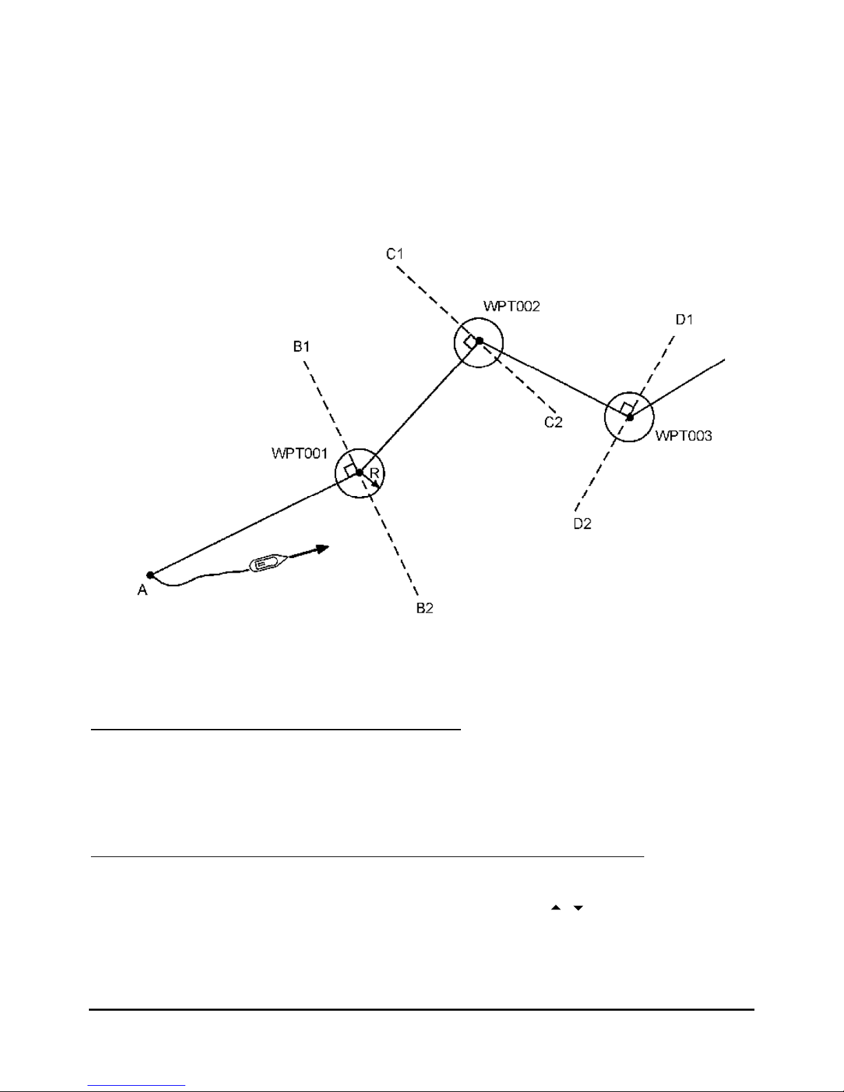
In the above example the vessel goes to waypoint WPT001. The GOTO ROUTE function
calculates the required navigational information to automatically move to waypoint WPT002
when the vessel moves into the circle of radius R, or when it crosses line B1 - B2 and so on,
until the last waypoint. The radius R is the distance programmed in the arrival alarm (see
NAVIGATION MENU).
4.2. – DEACTIVATE THE GOTO ROUTE FUNCTION
From the GOTO ROUTE function, press the
Menu
key then press the key 1 (or select 1-
DEACTIVATE and press
Enter
) to deactivate the GOTO ROUTE function.
4.3. – DISPLAY MODE SELECTION: DATA, COMPASS, 3D ROAD OR RADAR
From the GOTO ROUTE function, press the
Menu
key then press the key 2 (or select 2-
GOTO
DISPLA
Y and press
Enter
). Select the display mode using the
arrow keys then press
Enter
.
Page 23
FX312 & FX412 VERSION 2.0
MLR ELECTRONIQUE
23
Note: The DATA, COMPASS, 3D ROAD and RADAR displays are identical to those of the
GOTO WAYPOINT function.
4.4. – CHANGING THE ROUTE IN USE
From the GOTO ROUTE functio
n, press the
9
WXY List
key to display the list of your routes, then
select the new route to follow in the same way as paragraph 4.1 ACTIVATE THE GOTO
ROUTE FUNCTION.
4.5. – ENTER A NEW ROUTE
In your receiver you can enter a new route whilst following instructions from the windows
displayed when you press the
GoTo
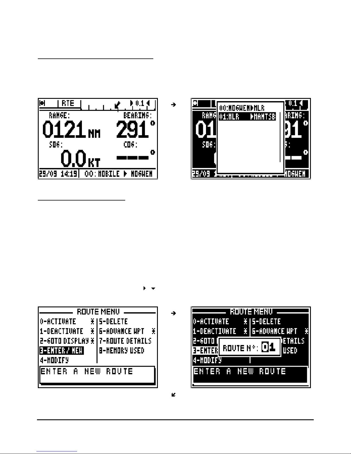
key or from the ROUTE MENU. From the ROUTE MENU,
press key 3 (or select 3-ENTER/NEW and press
Enter).
The first available route number is displayed. Press the
Enter
key if you wish to pr
oceed.
Should you wish to use an alternative number, make your choice and press
Enter.
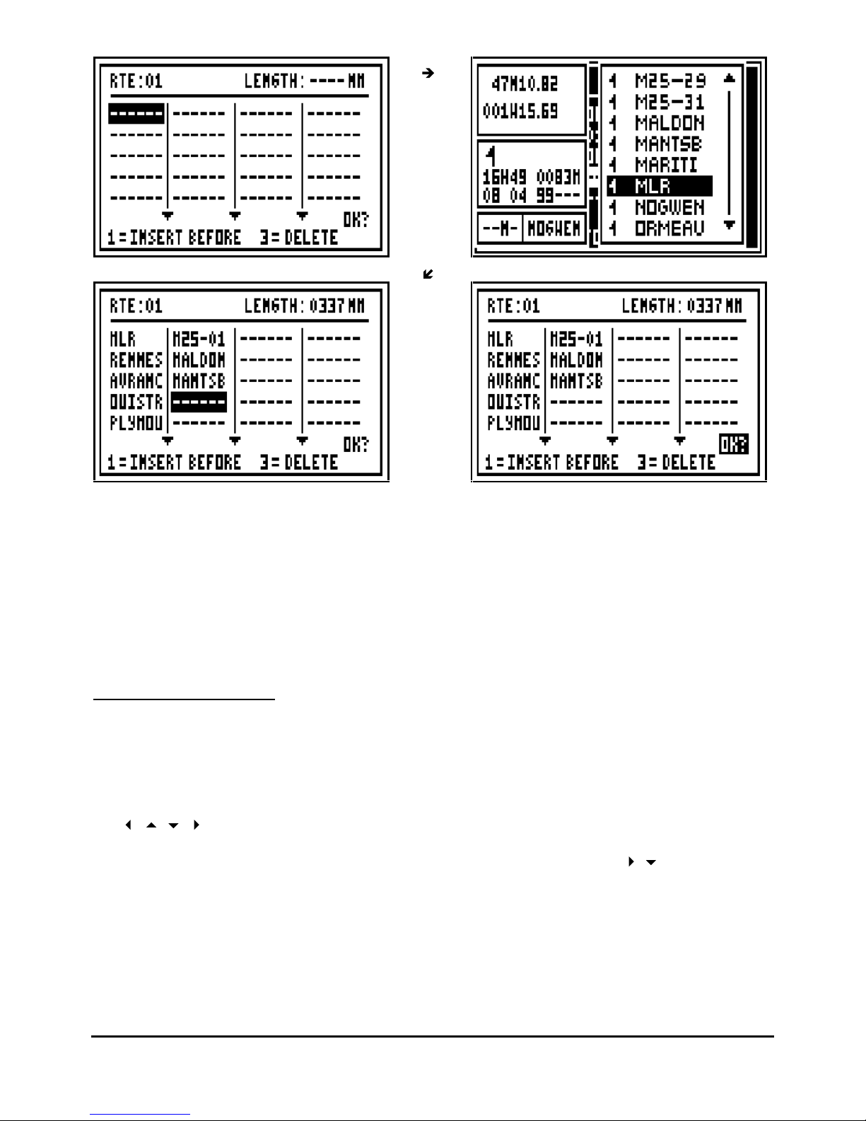
To display the list of waypoints now press key 9. Select your first waypoint then press
Enter
.
The name of this waypoint is displayed in the route and the cursor advances to the following
slot. Repeat this operation to enter all waypoints. When you have finished entering your route,
move the cursor to OK? using the
arrow keys and press
Enter
to validate and to store
your new route.
Page 24
FX312 & FX412 VERSION 2.0
MLR ELECTRONIQUE
24
No
te 1 : A route is made with a minimum of 2 waypoints and a maximum of 20 waypoints.
Note 2 : Once the route is entered the total length of the route is shown at the top right of the
display.
Tip : If you make any mistake while entering your route, you w
ill be able to correct it by pressing
the key 1 to INSERT A WAYPOINT BEFORE (before the cursor) or by pressing the key 3 to
DELETE A WAYPOINT.
4.6. – MODIFY A ROUTE
From the GOTO ROUTE function, press the
Menu
key then press key 4 (or select 4-
MODIFY
and
press
Enter
), the list of the route is displayed. Select from the list the route to modify and
press
Enter
.
The list of waypoints in the route will now be shown. Select the waypoints to be modified using
the
arrow keys or to place the cursor at the end of the list in order to add a new
waypoint in the route. Press the key 1 to insert a waypoint before the cursor. Press the key 3 to
delete a waypoint. To validate your modifications select the
OK?
using the
arrow keys and
press
Enter
.
Page 25
FX312 & FX412 VERSION 2.0
MLR ELECTRONIQUE
25
4.7. – DELETE A ROUTE OR ALL OF THE ROUTES
From the GOTO ROUTE function, press the
Menu
key then press key 5 (or select 5-
DELETE
and press
Enter
). Press the key 0 (or select 0-DELETE A ROUTE and press
Enter
). The list of
your routes is displayed. Select from the list the route to delete, press
Enter
to confirm.
To erase all the routes, press the key 1 (1
-DELETE ALL OF THE ROUTES) and confirm.
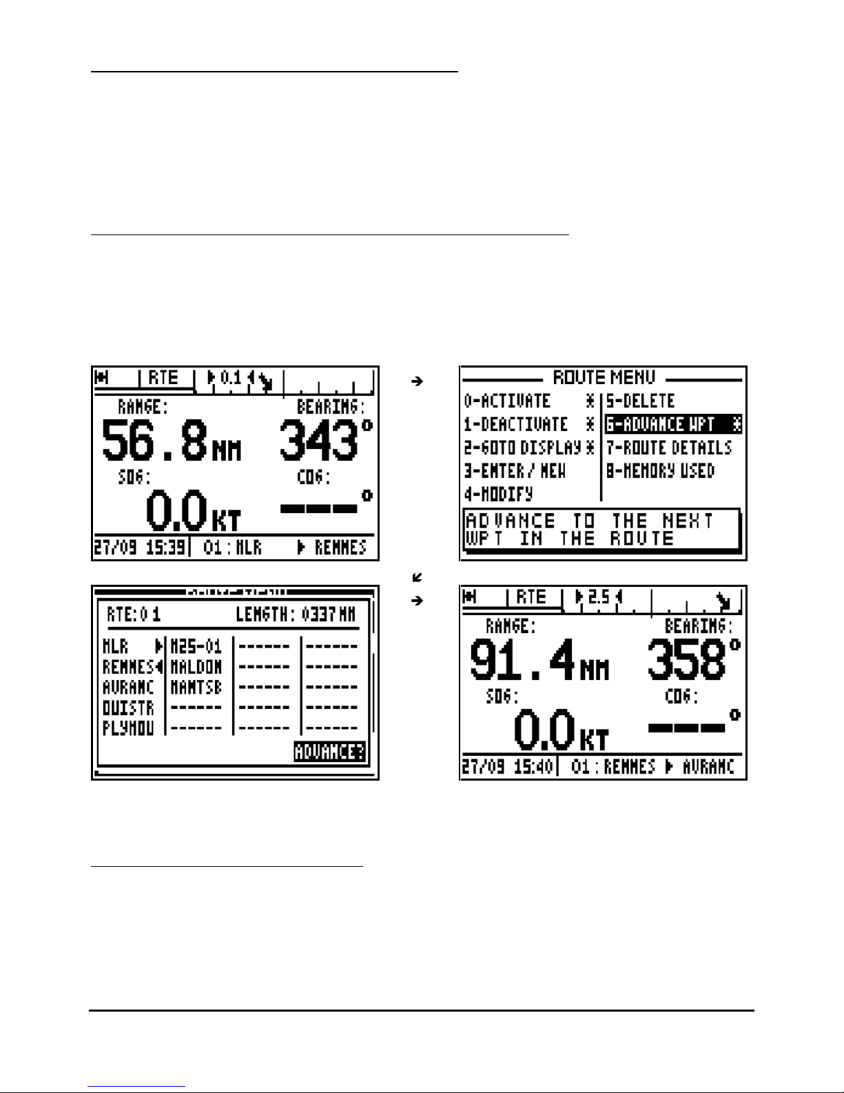
4.8. – ADVANCE TO THE NEXT WAYPOINT IN AN ACTIVE ROUTE
This function allows you to advance to the next waypoint (or to
change leg) in your route without
having to deactivate the route.
From the GOTO ROUTE function, press the
Menu
key then press key 6 (or select 6-
ADVANCE
WPT and press
Enter).
Tip: To advance several waypoints, repeat the operation as
required.
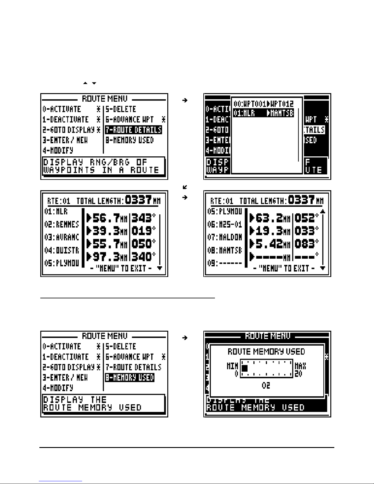
4.9. – DISPLAY THE ROUTE DETAILS
This function allows you to know the range and the bearing between each waypoints of the
route.
Page 26
FX312 & FX412 VERSION 2.0
MLR ELECTRONIQUE
26
From the GOTO ROUTE function, press the
Menu
key then the key 7 (or select 7-
ROUTE
DETAILS and press
Enter
). The list of the routes will be displayed, select the route and press
Enter
.
After one or two seconds, the names of the waypoints appear in the left column, the ranges
between the waypoints are displayed in the middle column and the bearings between the
waypoin
ts in the right column. The total length of the route is displayed at the top of the screen
Use the keys
to display the other waypoints of the route.
4.10. – ROUTE MEMORY : USED AND FREE MEMORY
From the GOTO ROUTE function, press the
Menu
key and press key 8 (or select 8-
MEMORY
USED and press
Enter).
Note: The capacity of the memory is 20 routes.
Page 27
FX312 & FX412 VERSION 2.0
MLR ELECTRONIQUE
27
5
– PLOTTER DISPLAY: VIEW YOUR TRACK AND CURRENT POSITION RELATIVE TO
SURROUNDINGS
The PLOTTER function shows a graphic representation of the route you have covered in
relation to the vessel current position (shown as a small circle), other entered waypoints and the
outline of the chart that may be entered with the PMS
(Personal Map System). This chart is 2
dimensional and the chart is always shown north up. This function may be configured within the
Plotter Menu.
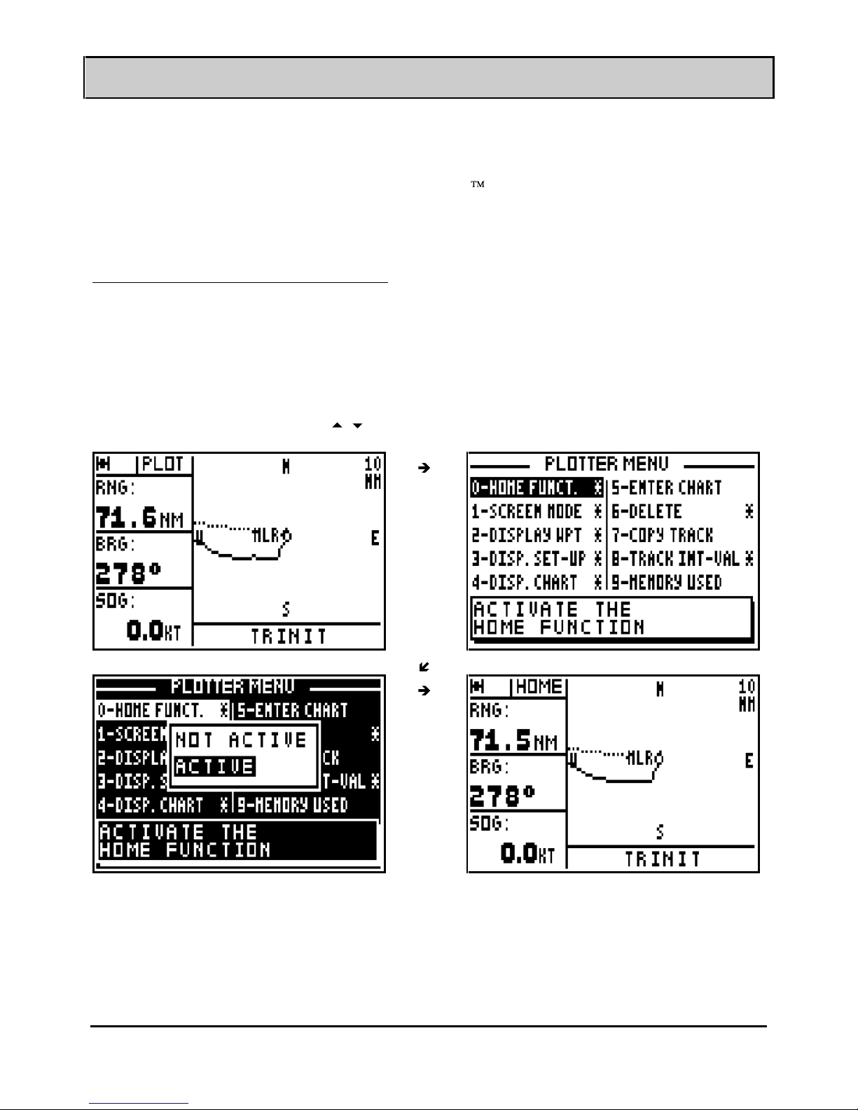
5.1. – ACTIVATE THE HOME FUNCTION
The HOME function stops the plotter from tracking to enable you to retrace your track to return
to your starting point.
From the PLOTTER function, press the
Menu
key and press key 0 (or select 0-HOME FUNCT.
and press
Enter
).
Select ACTIVE with the using the
arrow keys in the options menu and press
Enter
.
Note: When the HOME FUNCTION is active, the PLOT indicator shown in the top left of the
screen is replaced by the HOME indicator. To deactivate this function select the NOT ACTIVE
option from the Home Function (in the Plotter Menu).
Page 28
FX312 & FX412 VERSION 2.0
MLR ELECTRONIQUE
28
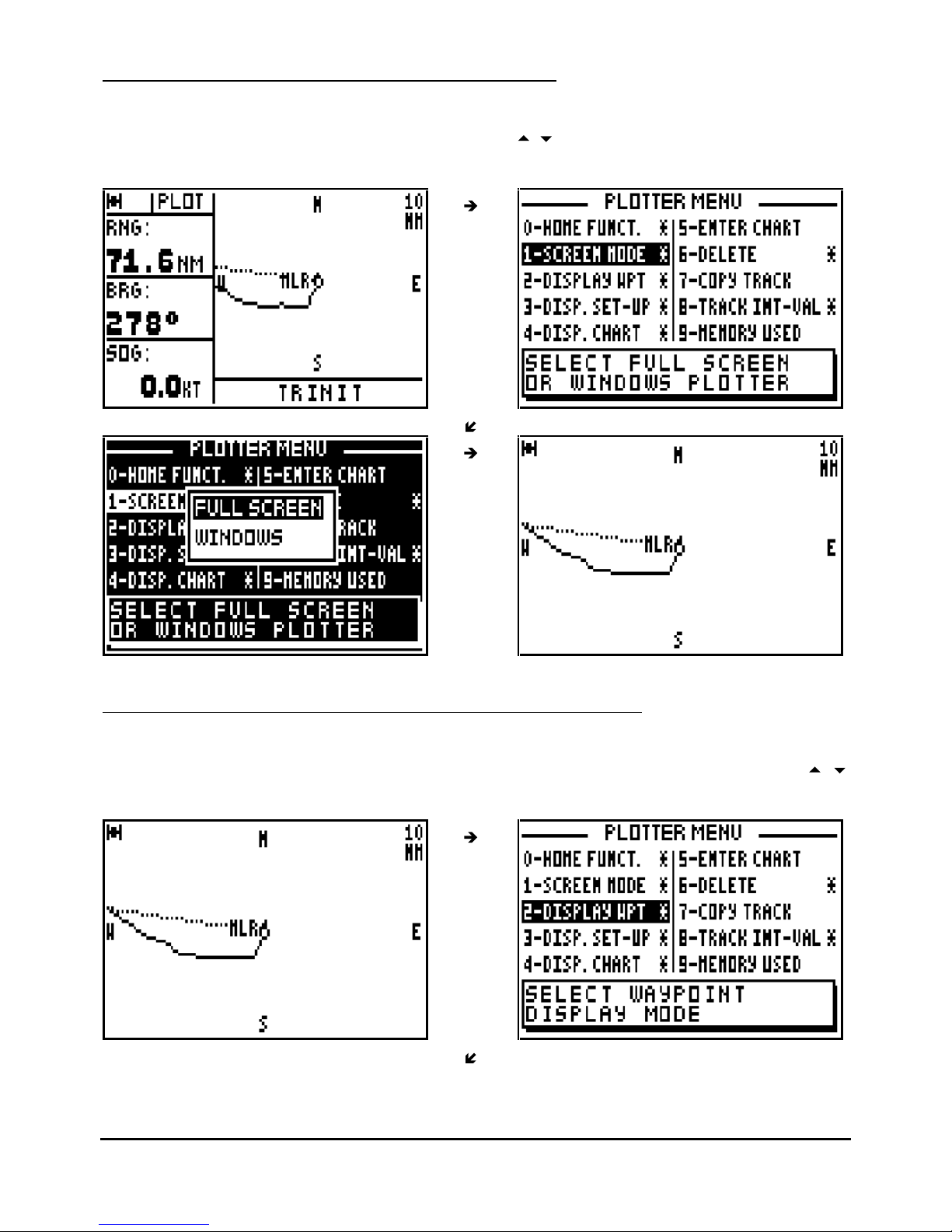
5.2. – SELECT THE FULL SCREEN OR WINDOW MODE
From the PLOTTER function,
press the
Menu
key and press key 1 (or select 1-SCREEN MODE
and press
Enter
). Select the desired mode using the
arrow keys and press
Enter
.
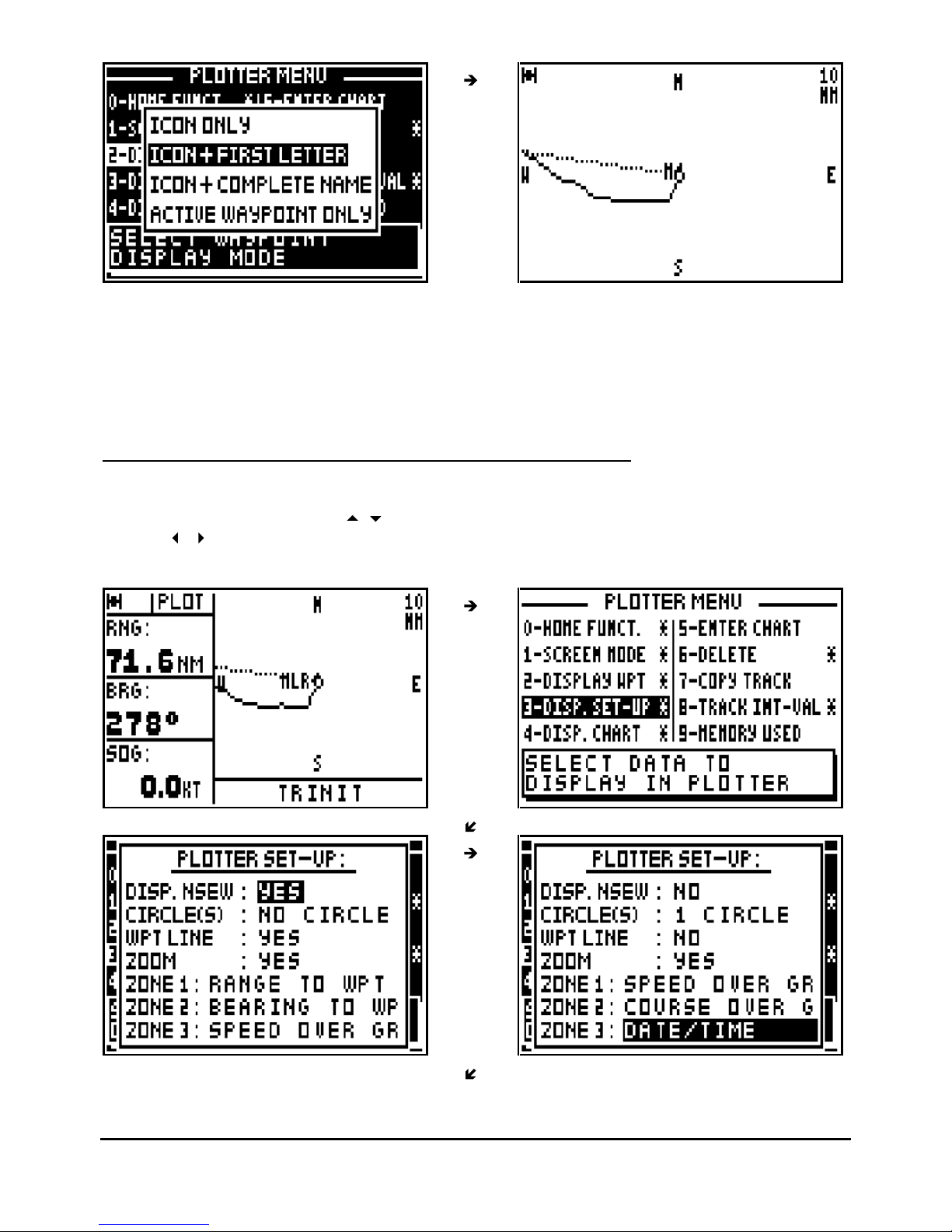
5.3. – SELECTION OF WAYPOINT NAMES ON PLOTTER DISPLAY
From the PLOTTER function, press
the
Menu
key and press key 2 (or select 2-DISPLAY WPT
and press
Enter
). Select the type of display required (i.e. Icon or full name) using the
arrow keys then press
Enter
.
Page 29
FX312 & FX412 VERSION 2.0
MLR ELECTRONIQUE
29
Waypoints can be represented by their icons only or by their icons plus the first letter of their
name or by their icons plus their complete name.
Tip : While choosing the ‘ACTIVE WAYPOINT ONLY’, only the icon of the active waypoint will
be displayed.
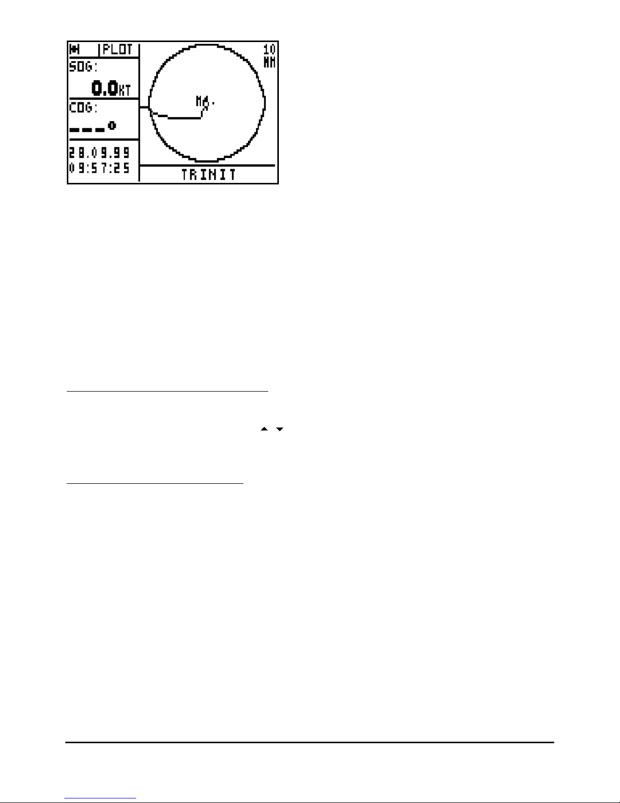
5.4. – SELECTION OF THE TYPE OF INFORMATION DISPLAYED
From
the PLOTTER function, press the
Menu
key and press the key 3 (or select 3-DISP. SET-
UP and press
Enter
). Use the
arrow keys to move the cursor within the set up menu and
use the
arrow keys to scroll through the different options available. When finished press
Enter to confirm your entries.
Page 30
FX312 & FX412 VERSION 2.0
MLR ELECTRONIQUE
30
DISP.NSEW
: you can choose to display the indications N (North), S (South), W (West) and E
(East) on the plotter screen to remind you its orientation.
CIRCLE(S)
: you can select to display none, 1 or 2 circles. The diameters of the circles are
shown either equal to the scale or alternatively half the scale.
WPT LINE : the WPT line is shown as a dotted line which starts at the vessel position when the
function was activated and it goes to the destination waypoint (GO TO WAYPOINT function).
This is the active waypoint in the GOTO route function. This is the reference line used for
calculating the cross track error.
ZOOM
: you have the option of displaying the value of the scale on the top right of the
PLOTTER screen.
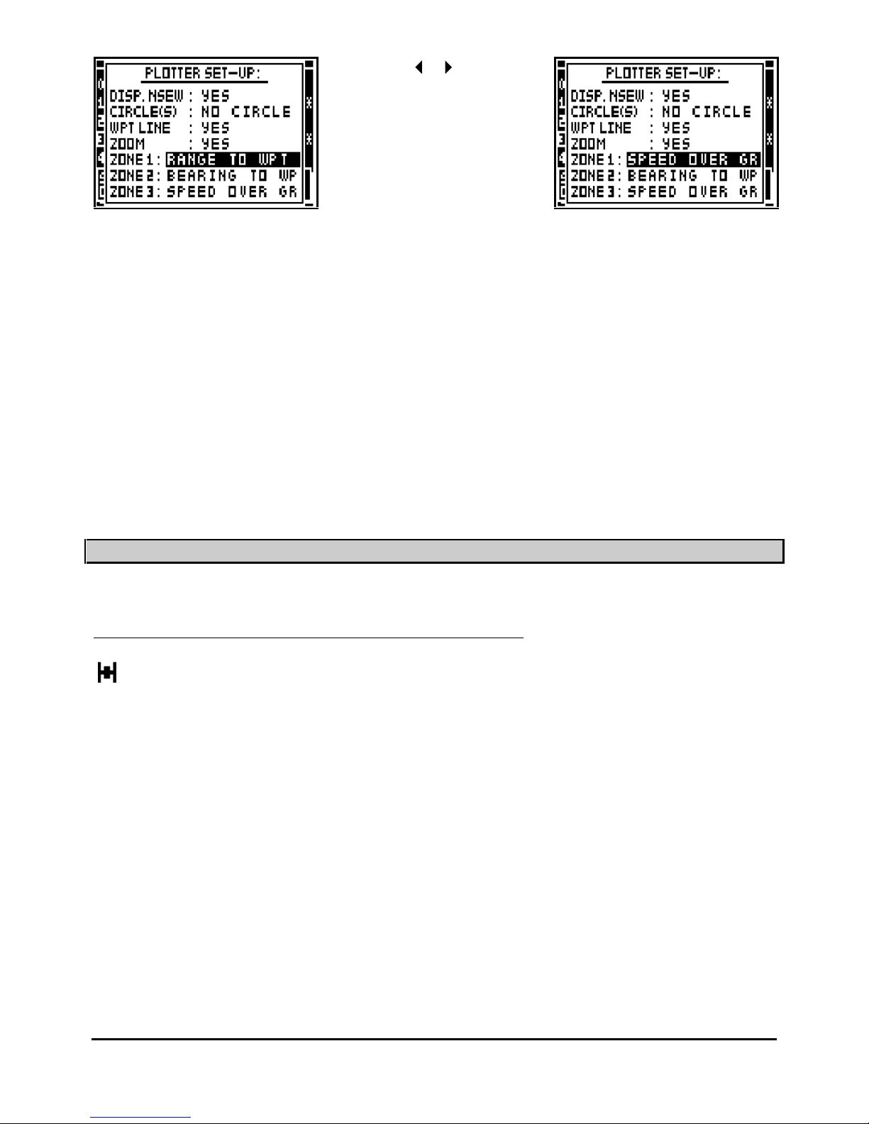
ZONES 1, 2 and 3 : you can select information displayed in these 3 zones from the Plotter set
up menu.
5.5. – DISPLAY THE CHART OUTLINE
From the PLOTTER function, press the
Menu
key and press the key 4 (or select 4-
DISP.
CHART and press
Enter
). Using the
arrow keys select the option CHART ON to display
the chart outline and press
Enter
.
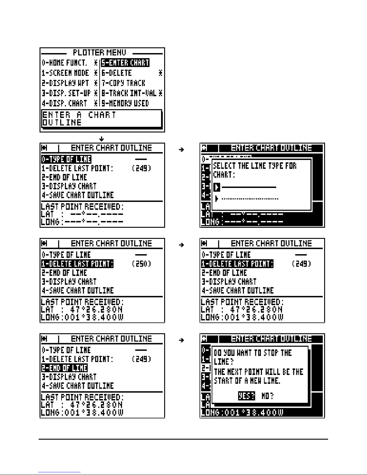
5.6. – ENTER A CHART OUTLINE
This function allows you to produce a chart outline from a paper chart with paper chart plotter or
to be loaded from a PC by using the software PMS, WAYPOINTS & ROUTES. This chart
outline can be displayed in the plotter function of your GPS.
To enter your chart outline, connect a YEOMAN plotter (see the connection in the installation
paragraph) to your receiver. To be used with the MLR DIGIPOINT, see paragraph B.10 and the
user manual of your DIGIPOINT.
From the PLOTTER function, press the
Menu
key and press the key 5 (or select 5-
ENTER
CHART and press
Enter
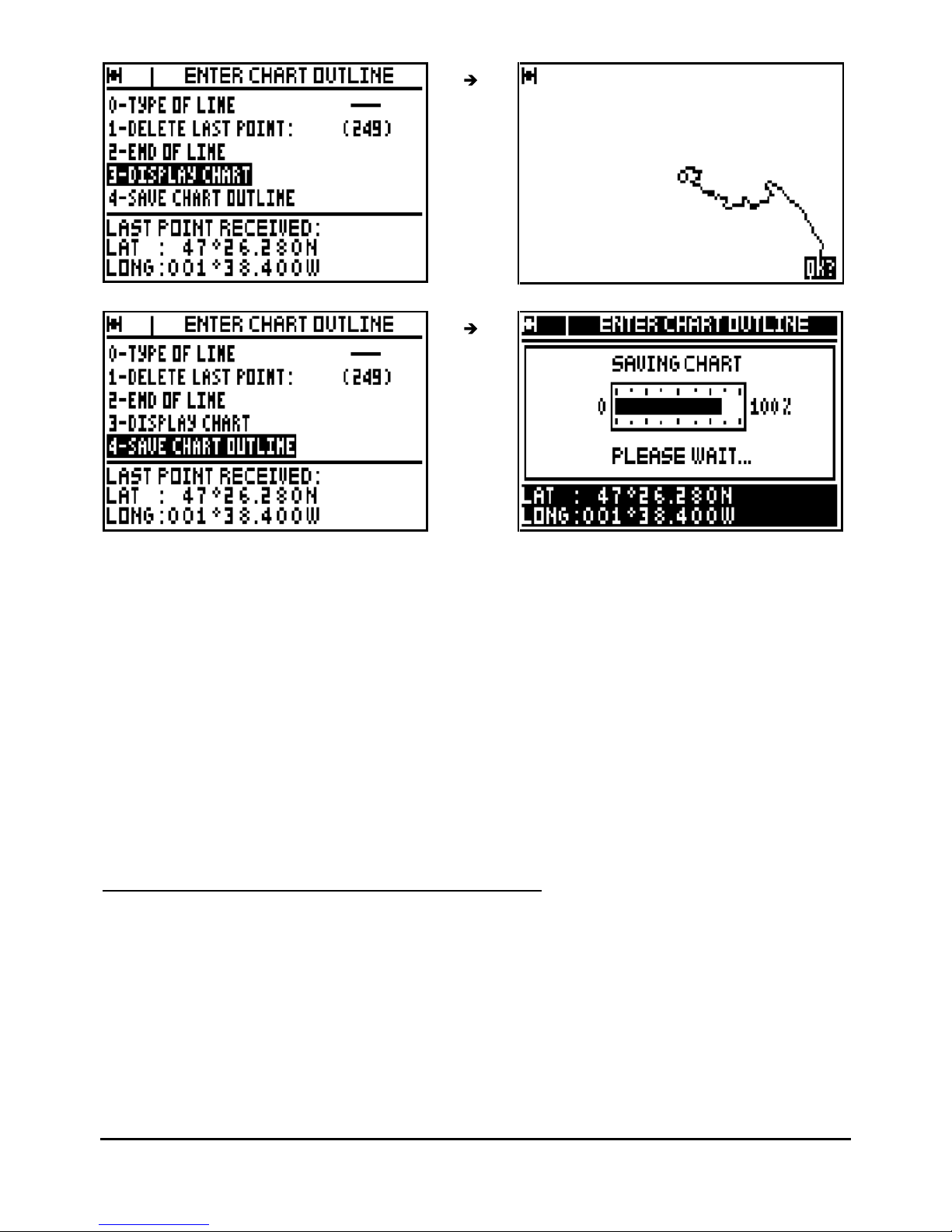
): The chart options menu is now displayed.
Us
e keys 0, 1, 2, 3 and
4:
0 - TYPE OF LINE, to select the type of line.
1 - DELETE LAST WAYPOINT, to erase the last received point in case of mistake.
2 - END OF LINE, to stop a line and to begin a new line.
3 - DISPLAY CHART, to display the outline
4 - SA
VE CHART OUTLINE, to validate and store the chart outline.
Page 31
FX312 & FX412 VERSION 2.0
MLR ELECTRONIQUE
31
Note: The position of the last received point is displayed at the bottom of the screen.
Page 32
FX312 & FX412 VERSION 2.0
MLR ELECTRONIQUE
32
Advice : When you have displayed the chart outline, press
Enter
to return to the chart options
MENU. To save your work it is imperative to select option 4 – SAVE CHART OUTLINE or to
confirm when the back-up window is displayed (this window is displayed after pressing a nonauthorised key).
Advice
: You can erase as many waypoints as you wish by selecting option 1 (1-DELETE LAST
POINT), this operation may be carried out as many times as necessary. The number of stored
points is automatically updated at the conclusion of this operation.
Note : To load a chart from a PC with the PMS WAYPOINTS & ROUTES software, proceed to
the following instructions : choose the NMEA183 format for the serial input, connect your
receiver to a PC using a serial port (connector DB-9, port COM1, COM2,…). Activate the
ENT
ER CHART OUTLINE function and start the loading from the PC. Once the waypoints are
loaded validate by pressing
Enter
.
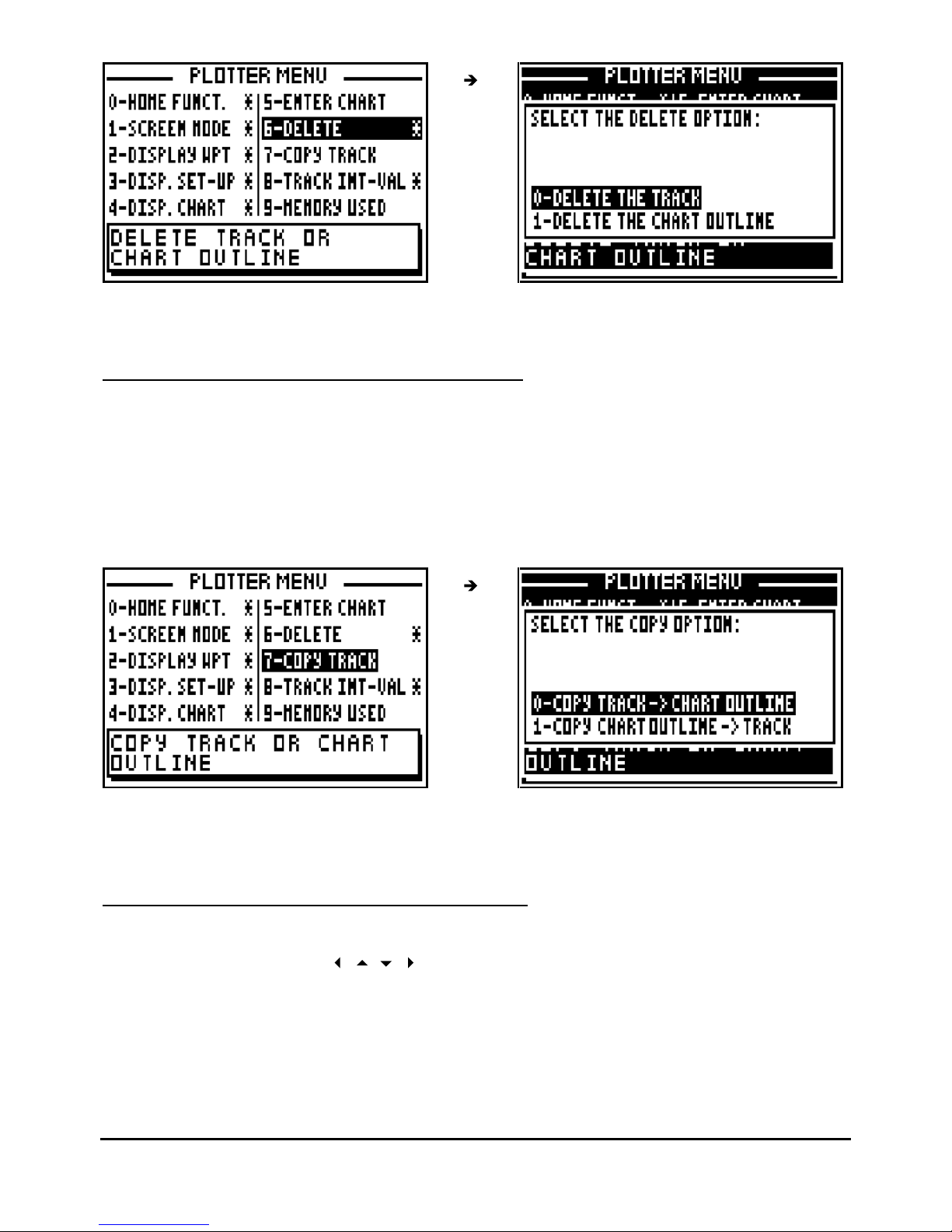
5.7. – DELETE THE TRACK OR THE CHART OUTLINE
From the PLOTTER function, press the
Menu
key and press key 6 (or select 6-DELETE and
press Enter
), then press the key 0 to delete the track or the key 1 to delete the chart outline,
and press
Enter
to confirm.
Page 33
FX312 & FX412 VERSION 2.0
MLR ELECTRONIQUE
33
Note : Once your chart outline has been erased, it cannot be reinstated.
5.8. – COPY THE TRACK OR THE CHART OUTLINE
This function allows you to copy your track in the memory of the chart outline or vice versa.
Depending of the use, you will be able to optimise these 2 memories of 250 points each.
From the PLOTTER function, press the
Menu
key and press key 7 (or select 7-COPY T
RACK
and press
Enter
), then press the key 0 to copy the track into the memory of the chart outline or
the key 1 to copy the chart outline into the memory of the track, and confirm.
Note : This operation is a copy. It means the copied memory (original memory) is not modified.
If you are willing to erase it, refer to the previous paragraph.
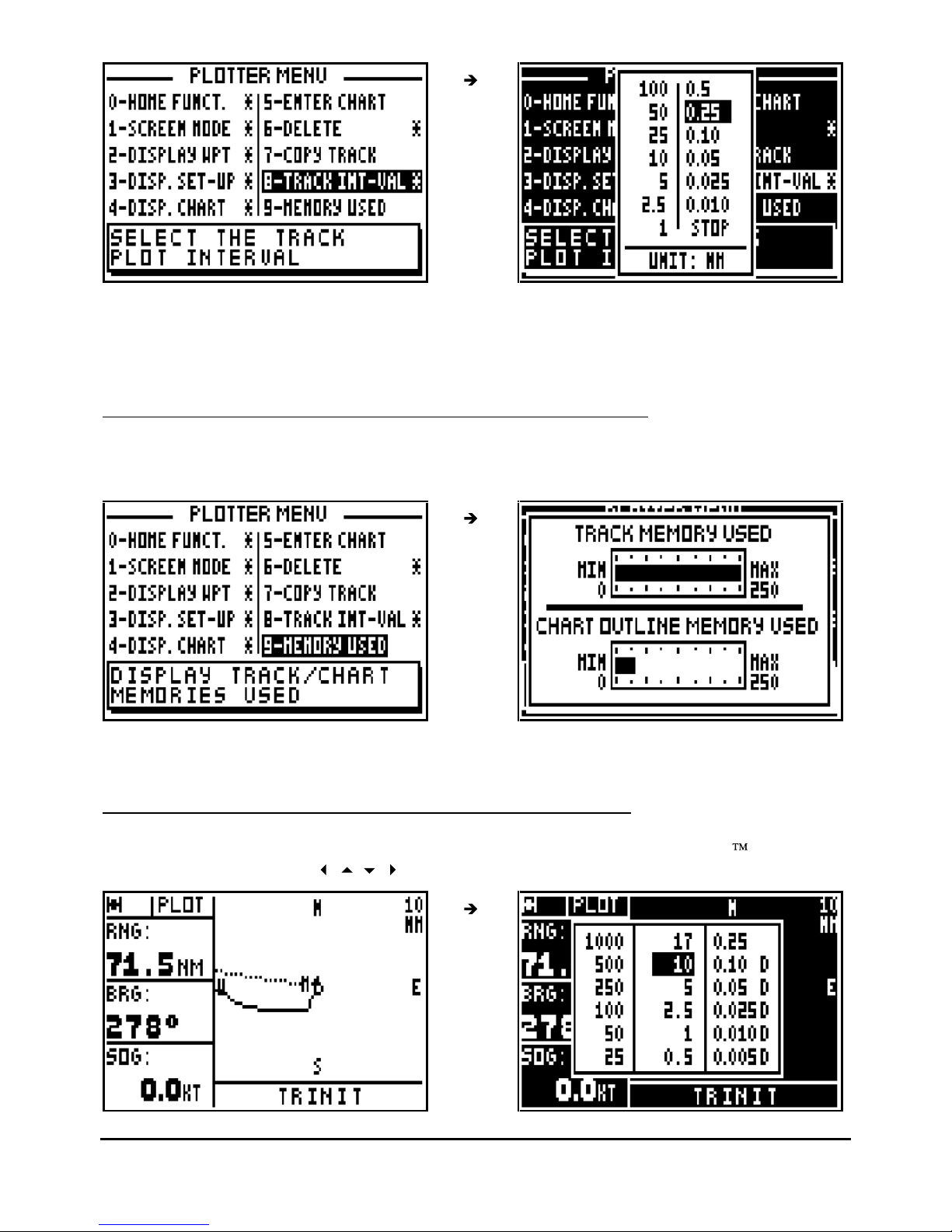
5.9. – SELECT TRACKING INTERVAL BY DISTANCE
From the PLOTTER function, press the
Menu
key and press key 8 (or select 8-TRACK INT-VAL
and press
Enter
). Using th
e
arrow keys select the desired track interval and press
Enter
.
Page 34
FX312 & FX412 VERSION 2.0
MLR ELECTRONIQUE
34
Advice : The track memory capacity is 250 points e.g. if you select the 1 km interval you will be
able to store 250 kilometres of track. If you select STOP your track will no
longer by stored. The
track up to this point will be stored.
5.10. – TRACK AND CHART MEMORY: USED AND FREE MEMORY
From the PLOTTER FUNCTION, press the
Menu
key and press key 9 (or select 9-
MEMORY
USED and press
Enter).
Note : The track memory
capacity is 250 points as well as the memory for the chart outline.
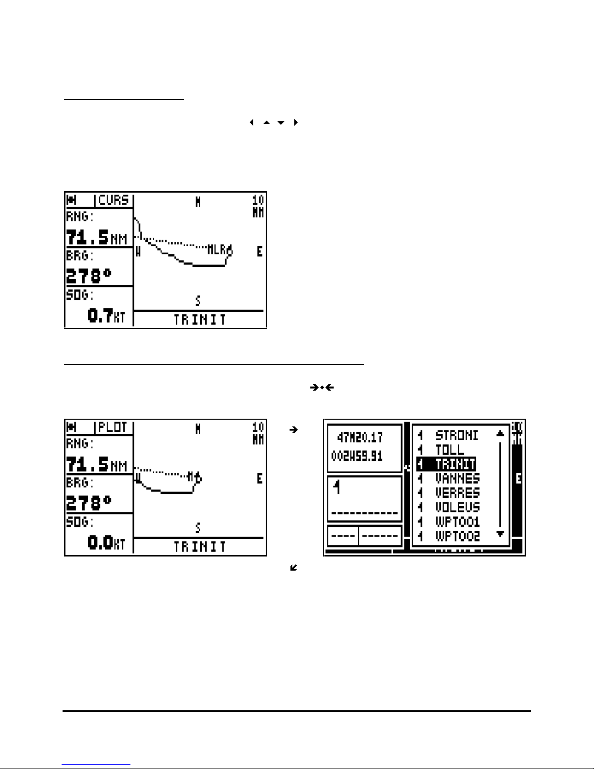
5.11. – CHANGE THE ZOOM SCALE ON THE PLOTTER SCREEN
From the PLOTTER function, press directly on to key 7
PRS
Zoom (Direct Access ), then select
the desired scale using the
arrow
keys and press
Enter
.
Page 35
FX312 & FX412 VERSION 2.0
MLR ELECTRONIQUE
35
Note : The value of the scale corresponds to the height of the screen. Scales with a D can be
used in differential mode.
5.12. – CURSOR MODE
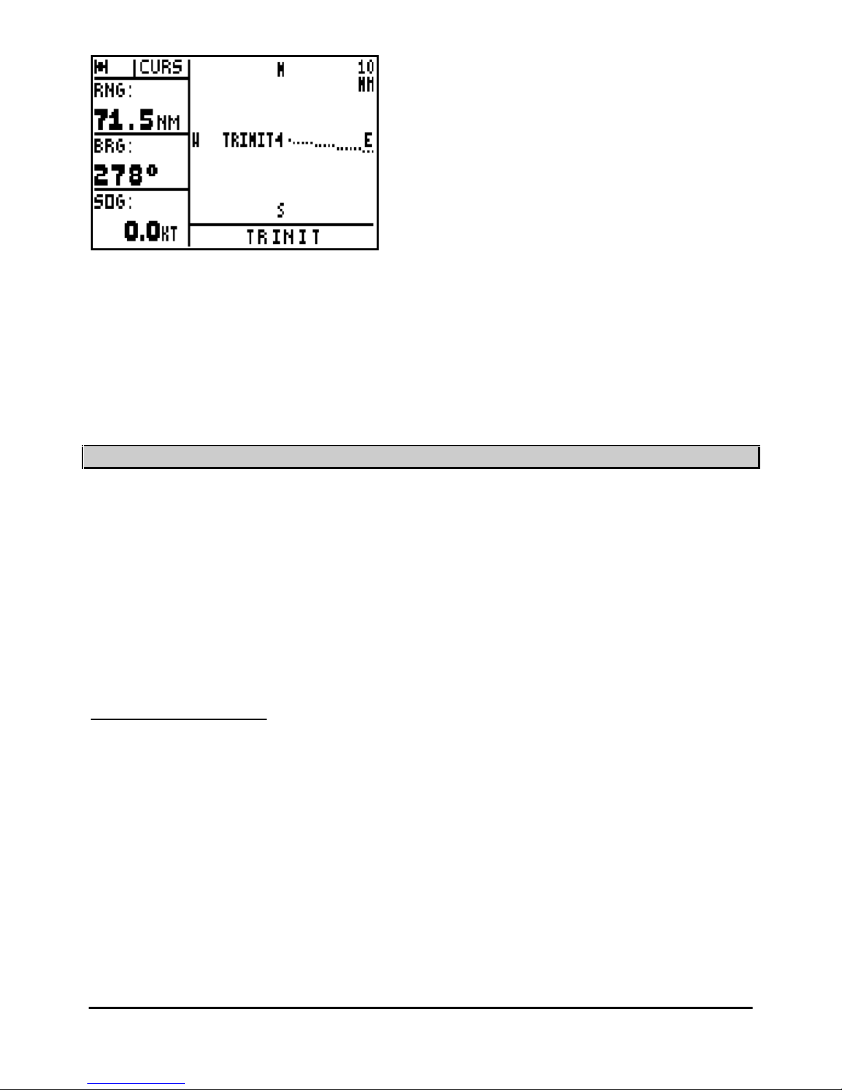
From the PLOTTER function use the
arrow keys to resite the plotter screen over an
object or position other than the vessels current position. When in this mode, CURS will be
displayed in the top left part of the screen instead of PLOT. This is to indicate that the plotter is
in CURSOR MODE. Pressing the
Plot
key again will enable you toreturn to the plotter mode
where the vessel position is centred on the screen.
5.13.
– CENTER THE PLOTTER SCREEN ON A WAYPOINT
From the PLOTTER function, press the key 5
JKL
: your waypoint list is displayed. Select
the waypoint you w
ant to appear in the middle of the screen and press
Enter
.
Page 36
FX312 & FX412 VERSION 2.0
MLR ELECTRONIQUE
36
Note : Press the
Plot
key will enable you to return to the plotter mode where the vessel position
is centred on the screen.
Tip : If your waypoint does not appear in the centre of the screen, it means you have chosen in
the paragraph B.5.3 the Active waypoint only option.
____________________
6 – MAN OVER BOARD (MOB) AND MARK FUNCTIONS
The MAN OVER BOARD and the MARK functions are activated with the
Mark/Mob
key. The
operati
on of these two functions depends on the MARK/MOB configuration within the SYSTEM
MENU (see chapter 7 paragraph C.7.1.7). Your GPS is pre-
set in MOB.
MOB function = One press only on the
Mark/Mob
key to activate the MAN OVER BOARD
(MOB) function.
MARK AND MOB function = One press only to activate the MARK (EVENT / WAYPOINT)
function and at least three presses to activate the MAN OVER BOARD (MOB) function.
6.1. – MOB ACTIVATION
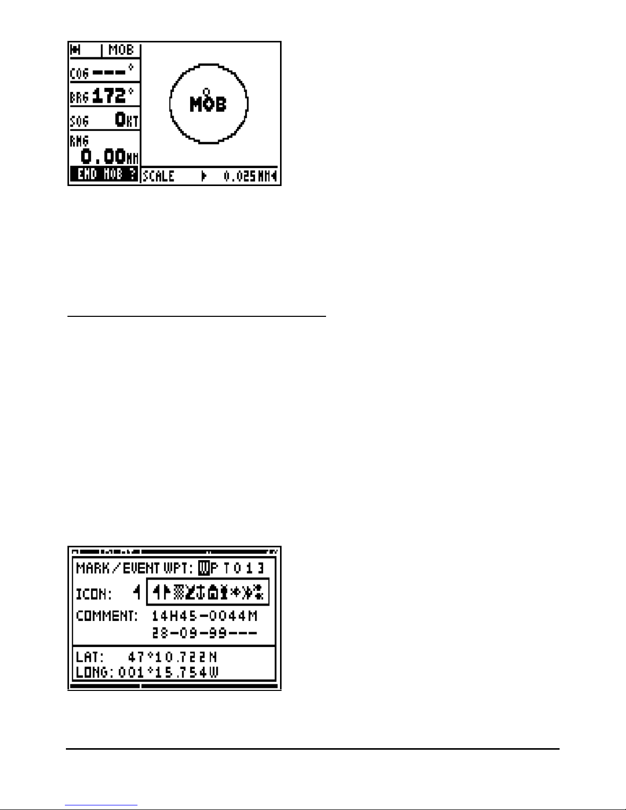
This function allows you to instantly record in an emergency your position
(e.g. man overboard).
The MOB function displays the bearing to follow to return to the MOB position. The distance,
your speed and course are also displayed. The circle in which the MOB is displayed is intended
to give greater accuracy for returning to the
MOB position. If you move off the MOB position, the
screen scale will be modified automatically to keep the MOB position permanently in the centre
of the screen.
Page 37
FX312 & FX412 VERSION 2.0
MLR ELECTRONIQUE
37
To stop the MOB function, press the
Enter
key when the MOB function is displayed.
Not
e: The plotter function (PLOT) is not available when the MOB function is active.
Advice: In practice, it is advisable to press the Mark/Mob key at least three times in order to
activate this function as this covers both configurations.
6.2. – MARK (EVE
NT / WAYPOINT) ACTIVATION
This function allows you to store event waypoint MARKS (or points of passage). An event
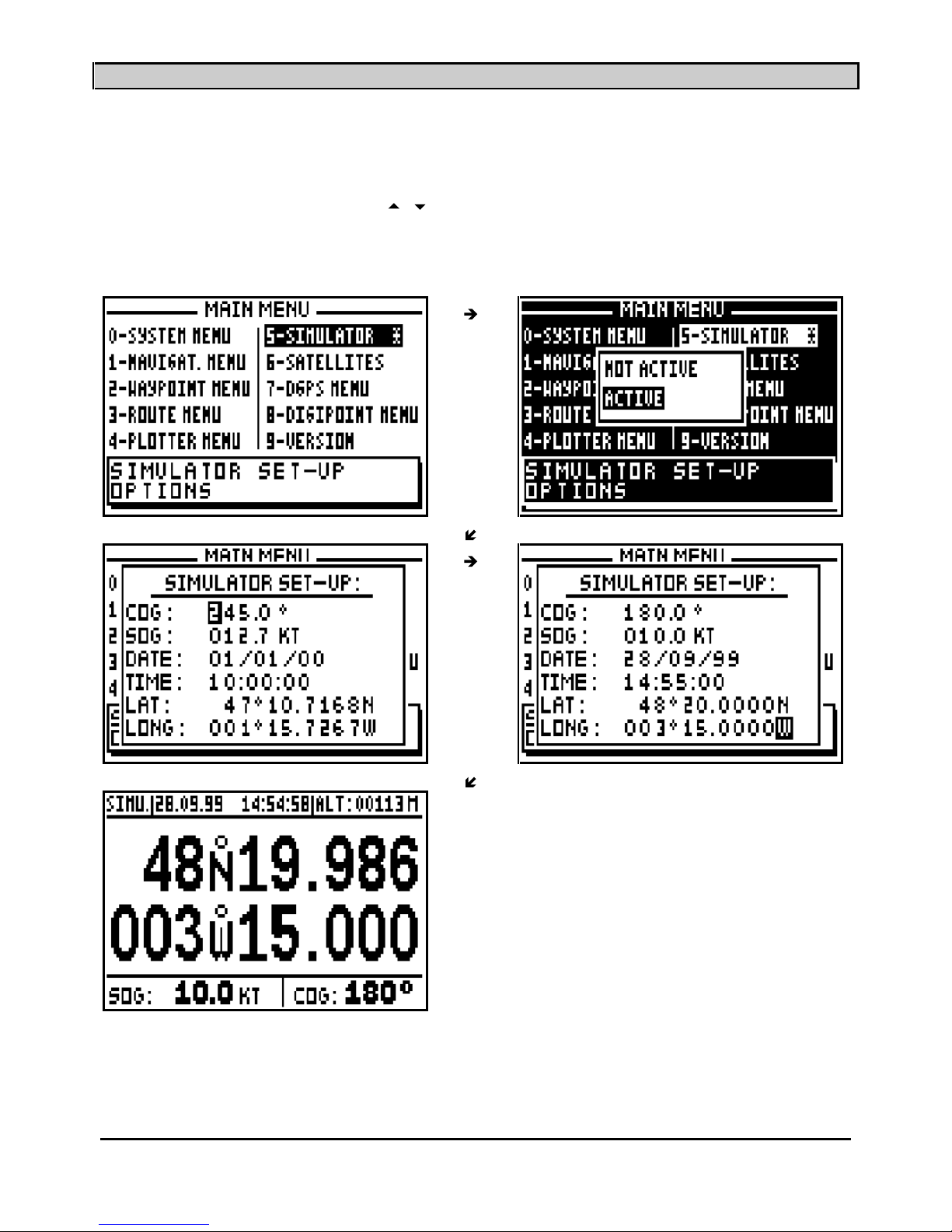
waypoint allows you to store very quickly and easily the position of an object at your current
position. This function is only available whe
n your GPS is set to MARK AND MOB.
From any function you may press the Mark/Mob key to display a list of event waypoints. This
window is very similar to the waypoint list window. A name, an icon and a comment are
proposed, press
Enter
to accept them or
to validate your modifications.
The proposed name is formed by the three WPT letters and three figures in numerical order e.g.
WPT001, WPT002, WPT003...
The proposed icon is a flag.
The proposed comment comprises of the time, the altitude and the date calculated by the
receiver at the time you press on the
Mark/Mob
key.
Tip: You can alter the Mark / Event waypoint by using MODIFY from the WAYPOINT MENU.
____________________
Page 38
FX312 & FX412 VERSION 2.0
MLR ELECTRONIQUE
38
7
– SIMULATOR FUNCTION
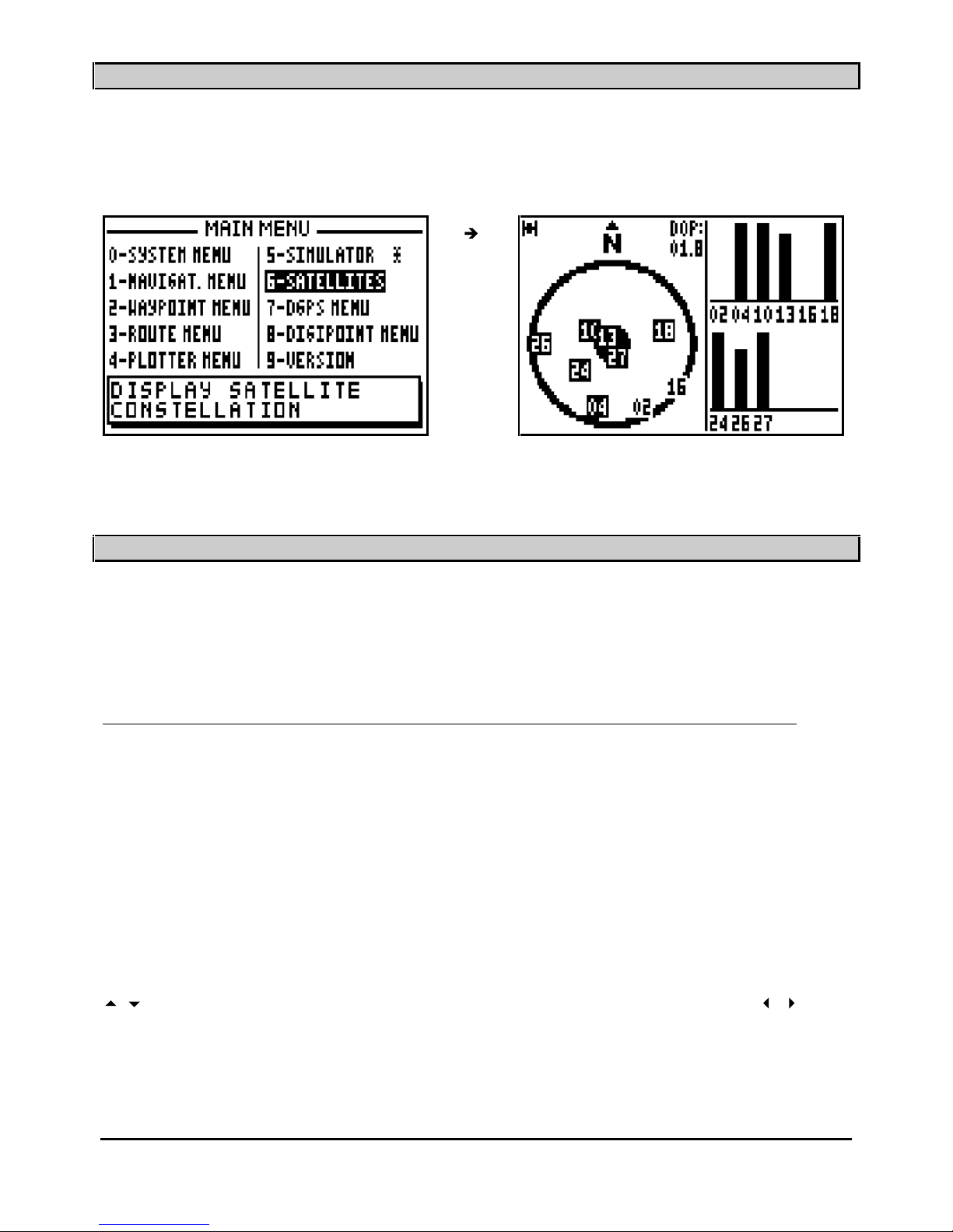
This function allows you to simulate all the na
vigation functions available in your GPS.
To activate the SIMULATOR function, from the MAIN MENU, press key 5 (or select 5-
Simulator
and then press
Enter
). Using the
arrow keys, select ACTIVE from the ACTIVE/NOT
ACTIVE window and press
Enter
. In the displayed window, enter the different navigation
parameters, e.g. COURSE, SPEED, DATE, TIME and the start position (LATITUDE and
LONGITUDE) then press the
Enter
key.
Note: When the simulator is active, the SIMU indication is displayed on the top left of the
screen. To stop the simulator function, select NOT ACTIVE from the ACTIVE/NOT ACTIVE
window and press the
Enter
key.
____________________
Page 39
FX312 & FX412 VERSION 2.0
MLR ELECTRONIQUE
39
8 – SATELLITES
From the MAIN MENU, press key 6 (or select 6
-SATELLITES and press
Enter
).
You will find further information about satellites in the chapter C, paragraph 2, SATELLITES.
____________________
9 – TO USE THE FX312 OR THE FX412 IN DIFFERENTIAL MODE
You will find in this chapter 3 paragraphs describing : the use o
f the FX312 with the MLR DF300
differential beacon receiver, the use of the FX312 with another differential beacon receiver and
the use of the FX412 in differential mode.
9.1. – USING THE FX312 WITH THE MLR DF300 DIFFERENTIAL BEACON RECEIVER
The DF300 is a DGPS receiver from the MLR range. It has been designed so that it may be
controlled entirely from your FX312. Connect the FX312 to the DF300 while following
instructions from paragraph E – INSTALLATION INSTRUCTIONS and configure the data input
of the F
X312 for DIFFERENTIAL format.
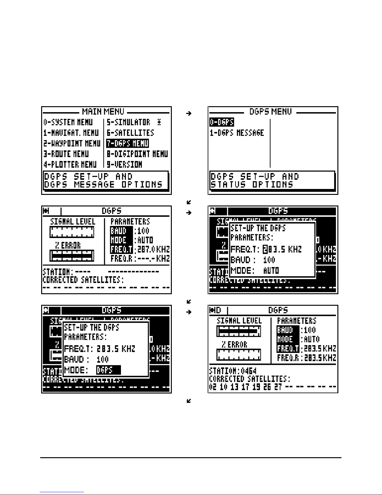
From the MAIN MENU press key 7 (or select 7-DGPS MENU and press
Enter
), then press the
key
0 to select 0-DGPS. On the left of the screen the signal strength is displayed by a
bargraph, (a good signal = 3/4 of black in the
bargraph) and the percentage of error on the data
should be a low figure. At the bottom of the screen the DGPS station identification number is
displayed together with a list of the satellites which are being corrected.
To change parameters of the DF300, press the
Enter
key to display the options menu. Use the
arrow keys to move the cursor in the window. Use the numeric keys and the
arrow
keys to enter your new parameters then press
Enter
to validate.
DGPS PARAMETERS:
FREQ.T = Frequency of the sta
tion to receive (frequency transmitted to the DF300).
Page 40
FX312 & FX412 VERSION 2.0
MLR ELECTRONIQUE
40
BAUD = Data transmission speed of the DGPS station. (rate transmitted to the DF300).
MODE = Working Mode of the FX312 (Normal, Diff and Auto)
NORMAL = Calculation of the position will take place without differential corrections but if
differential corrections are found they will be applied.
DIFF = Calculation of the position with differential corrections, if the differential signal is not
found the position is not calculated.
AUTO = The FX312 selects the best mode, either Normal or Diff, according to the differential
corrections being received.
FREQ.R = DGPS frequency that the DF300 receives and operates on.
Page 41
FX312 & FX412 VERSION 2.0
MLR ELECTRONIQUE
41
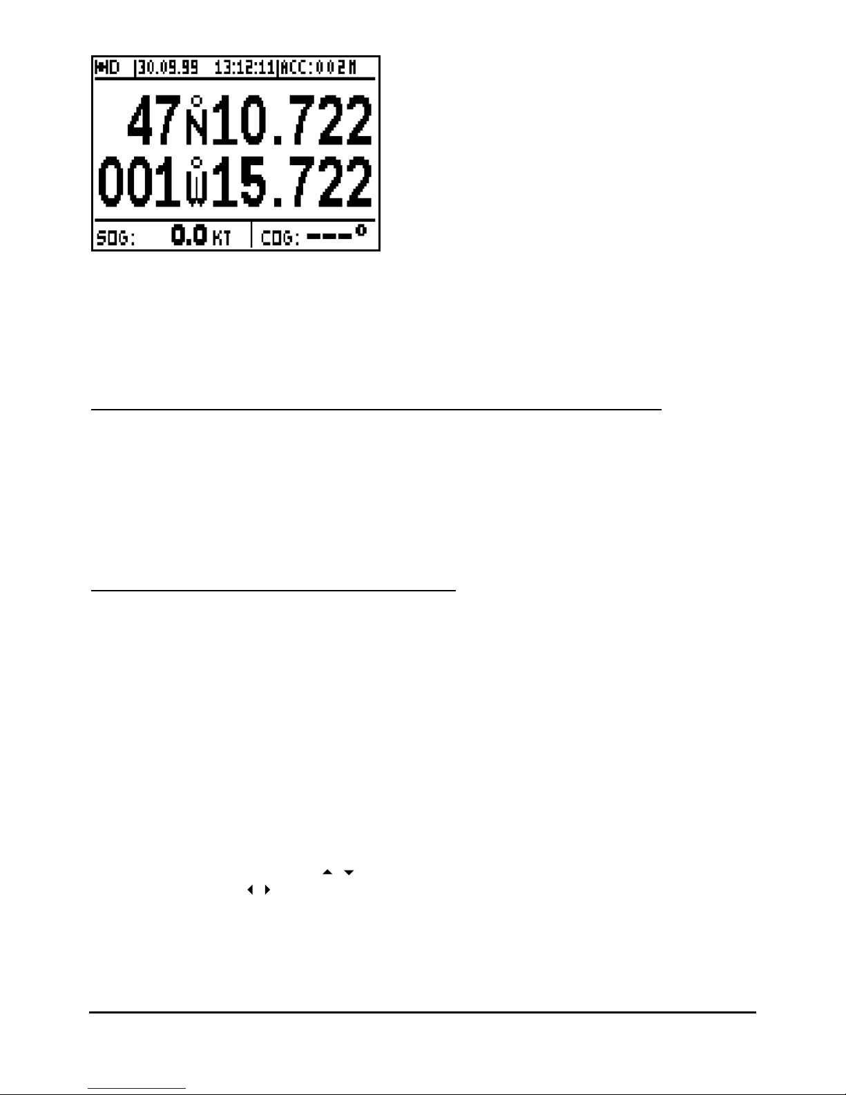
Note: the D letter is displayed in the top left of the
screen when the FX312 calculates its position
in differential mode. The indication of accuracy (ECP) automatically takes into account the
precision of the differential mode.
Tip: The Annex 4 of your manual contains a list of DGPS station frequencies.
9
.2. – USING THE FX312 WITH OTHER MANUFACTURERS DGPS RECEIVERS
Connect the FX312 to the DGPS receiver with the help of instructions in Paragraph 3
(INSTALLATION INSTRUCTIONS) and configure the data input of the FX312 for
DIFFERENTIAL format. Select the wo
rking mode for the GPS (see previous paragraph). Please
read your DGPS receiver manual for further information. When using the DGPS receiver a D is
displayed on the top left of the screen when the FX312 calculates its position in differential
mode.
9.3. – USING THE FX412 IN DIFFERENTIAL MODE
The FX412 is a GPS navigator with an integrated DGPS receiver, which can operate in the
DGPS mode without any other equipment. However it is possible for test purposes to use an
external DGPS receiver should this be
desired.
To use your FX412 in the DGPS mode, you just have to select the DGPS station you wish to
receive, your FX412 will automatically ensure the correct reception, decoding and the
processing of the DGPS information. When the FX412 calculates the position in DGPS mode,
the letter D is display in the top left
-hand corner of the screen near the satellite symbol.
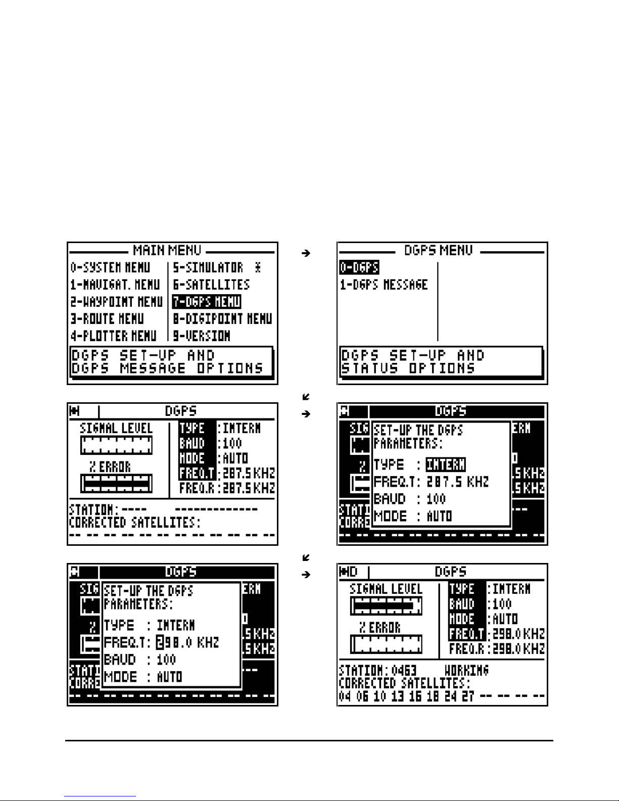
From the MAIN MENU press key 7 (or select 7-DGPS MENU and press
Enter
), then press the
key 0 to select 0-DGPS. On the left of the screen the sig
nal strength is displayed as a bargraph,
(a good signal = ¾ of black in the bar graph) and the percentage of error on the data should be
a low figure. At the bottom of the screen the DGPS station identification number is displayed
together with a list of
the satellites which are being corrected.
To change the DGPS parameters of the FX412, press the
Enter
key to display SET-UP THE
DGPS PARAMETERS. Use the
arrow keys to move the cursor in the window. Use the
numeric keys and the
arrow keys to enter
your new parameters then press
Enter
.
DGPS PARAMETERS:
TYPE = Selection of the internal DGPS receiver of the FX412 or of an external DGPS receiver.
FREQ. T
= Frequency of the station to receive (frequency transmitted to the DF300).
Page 42
FX312 & FX412 VERSION 2.0
MLR ELECTRONIQUE
42
BAUD = Data transmissi
on speed of the DGPS station. (Rate transmitted to the DF300).
MODE = Working Mode of the FX412 (Normal, Diff and Auto)
NORMAL = Calculation of the position will take place without differential corrections.
If differential corrections are found they will
be applied.
DIFF
= Calculation of the position with differential corrections, if the differential
signal is not found the position is not calculated.
AUTO = The FX412 selects the best mode, either Normal or Diff, according to the
differential corrections
being received.
FREQ.R
= DGPS frequency that the FX412 (or external DGPS receiver) receives and operates
on.
To use your FX412, be sure that you have correctly selected INTERN for the TYPE, and AUTO
or DIFF for the mode together with the correct DGPS sta
tion (frequency and Baud rate) with the
help of ANNEXE 4.
Page 43
FX312 & FX412 VERSION 2.0
MLR ELECTRONIQUE
43
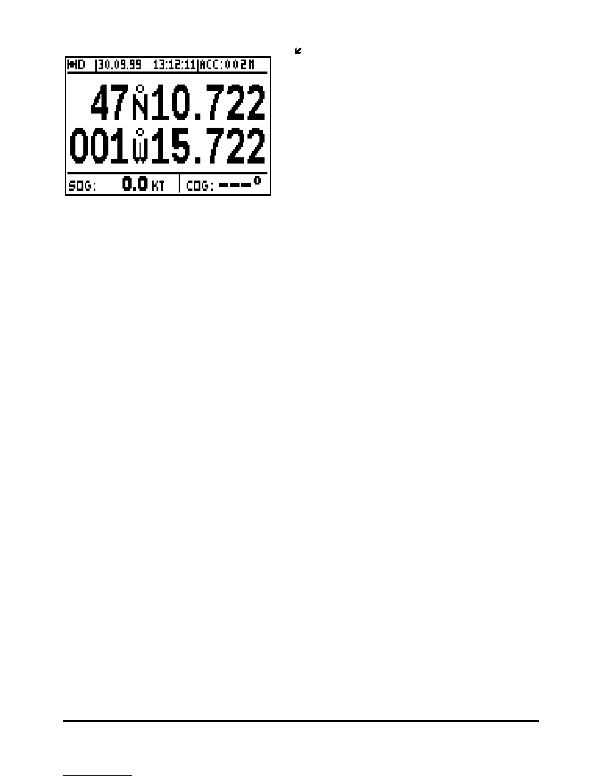
Note 1 : The D letter is displayed in the top left of the screen when the FX412 calculates its
position in differential mode. The indication of accuracy (ECP) automatically takes into account
the precision of the differential mode.
Tip : Select the nearest DGPS station using the ANNEXE 4. If after 5 minutes your FX412 does
not work in DGPS mode, check the data entered or try other stations.
Note 2 : You can also use an external DGPS receiver. In order to proceed, connect the FX412
to the DGPS receiver with the help of instructions in Chapter E (INSTALLATION
INSTRUCTIONS) and configure the data input of the FX412 for DIFFERENTIAL format. Set up
your FX412
on EXTERN for the TYPE and select the working mode for the DGPS (see previous
paragraph). Please read your DGPS receiver manual for further information. The letter ‘D’ is
displayed on the top left of the screen when the FX412 calculates its position in di
fferential
mode.
____________________
Page 44
FX312 & FX412 VERSION 2.0
MLR ELECTRONIQUE
44
10 –
USE OF DIGIPOINT TO ENTER WAYPOINTS, ROUTES AND CHART OUTLINE
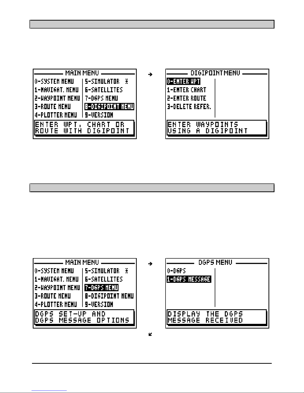
Thanks to DIGIPOINT you will be able to enter easily waypoints, routes and chart outline. From
the MAIN MENU, press key 8 (or select 8-DIGIPOINT MENU and press
Enter
). For a complete
use of DIGIPOINT, refer to the DIGIPOINT user’s manual.
____________________
11 –
DGPS RECEPTION MESSAGES
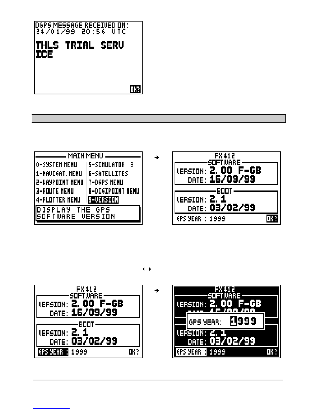
An M displayed on the top left of the screen indicates the reception of a message from the
differential correction station.
From the MAIN MENU, press key 7 (or select 7-DGPS MENU and press
Enter
), then press the
key
1 to select 1-DGPS MESSAGE and read the received message. Press the
Enter
key to
delete the DGPS message. To save the message, leave the MESSAGE on the screen whilst
pressing one of the function keys,
Pos, Nav, GoTo, Plot
or
Menu
.
Page 45
FX312 & FX412 VERSION 2.0
MLR ELECTRONIQUE
45
____________________
12 –
SOFTWARE VERSION AND GPS YEAR OF YOUR RECEIVER
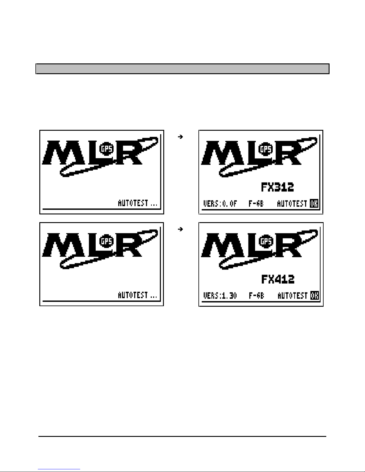
From the MAIN MENU press key 9 (or select 9-VER
SION and press
Enter
) to read the software
and the boot version as well as the GPS year which is used as a reference .
The GPS system uses a time reference which counts the weeks and the seconds in a week,
with a reset every 1024 weeks. This reset has occurred this year in the night of the 21
st
August
1999. The next reset will be in the night of the 5
th
of April 2019. To avoid any problem, your
receiver display the year in the VERSION screen as a reference which you will have to update
before the s
pecific date (once every 20 years! ! ! ).
To update the GPS year, press the key
to select the GPS YEAR, press
Enter
, enter the
year and then press
Enter
.
Note : Be careful, your receiver might not work properly if you enter a wrong date.
Page 46
FX312 & FX412 VERSION 2.0
MLR ELECTRONIQUE
46
C – B
EGINNERS GUIDE
1 – POWER ON/OFF
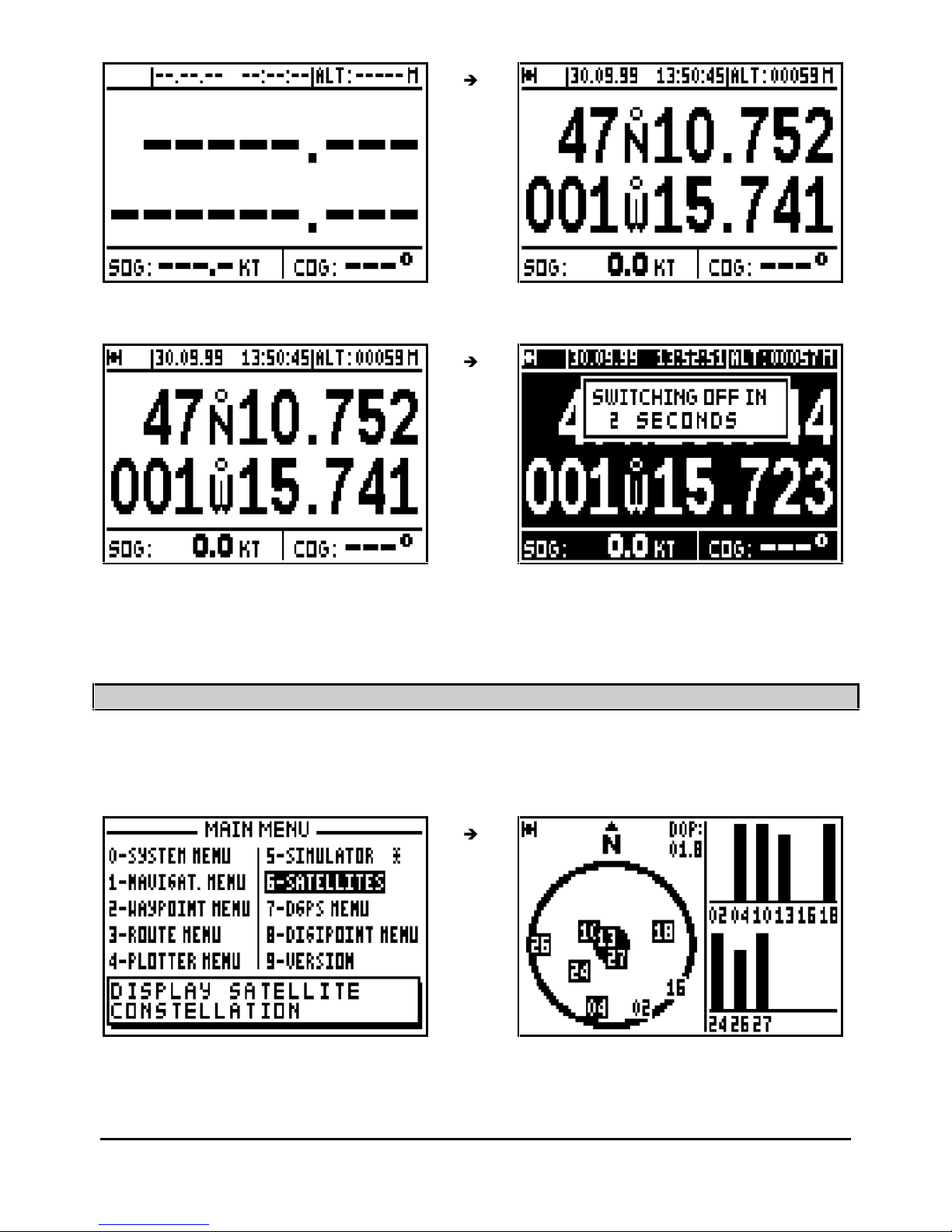
Press the
PWR
key to switch on your GPS, an audible beep is given out and the FX312 begins
a sequence of autotests. Then, the FX312 (or FX412) indication, the software version and OK
are displayed. From this moment you have access to all functions. If no function is selected
within 10 seconds, the POSITION function is displayed.
The date and the time are displayed on receipt of the first satellite signal. When sufficient
satell
ite signals are received : the position, altitude, speed and the course are calculated. The
symbol representing a satellite is displayed in the top left of the screen indicating that your GPS
is receiving enough satellite signals to calculate and validate
its position.
Page 47
FX312 & FX412 VERSION 2.0
MLR ELECTRONIQUE
47
To switch off your GPS press
PWR
and hold down until unit powers down.
____________________
2 – SATELLITES
From the POSITION function press the
Menu
key and press key 6 (or select 6-SATELLITES
and press
Enter) to vie
w the satellites and signal strengths being received.
The left hand side of the screen details currently received satellites. The outside circle
represents the horizon and the central disk represents the zenith. A satellite close to the outside
Page 48
FX312 & FX412 VERSION 2.0
MLR ELECTRONIQUE
48
c
ircle will present a very weak elevation over the horizon; it will be difficult to receive. A satellite
close to the centre has a greater elevation (close to 90°); it will be received without any problem.
In the right part a bargraph details the quality of reception of every satellite, no bar = no
reception, black bar at 3/4 of the height = perfect reception. The D O P (Dilution of Position) is
an indication of calculated accuracy of the horizontal position, this depends on the respective
positions of sat
ellites in relation to each other. The best accuracy will be obtained when the D O
P (Dilution of Position) is 1.
Note 1 : Every GPS satellite circles the earth in 11 hours and 58 minutes. According to the time
of day the number of available satellites in the sky varies from 6 to 12. On average 9 satellites
are visible.
Note 2 : The fact that the satellites are always above your antenna, implies that the altitude
accuracy is 2 times less than the position accuracy.
____________________
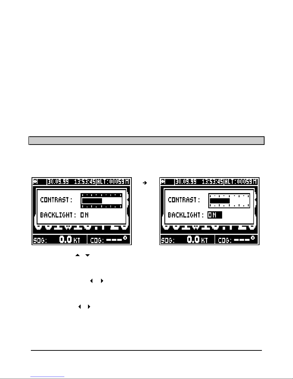
3 – CONTRAST AND
BACKLIGHT ADJUSTMENT
When the receiver is on, briefly press the
PWR
key to illuminate the display and keyboard. This
action will also activate the display menu.
Use the vertical
arrow keys to move the cursor from contrast to backlight or
from
backlight to contrast.
Contrast:
To use the horizontal
arrow keys to adjust the contrast when the cursor is on the
contrast bargraph.
Light:
Use the horizontal
arrow keys to switch the backlight on or off .
Press
Enter
to validate your adj
ustment and to erase the window.
Tip: To illuminate the GPS quickly press
PWR
and
Enter
.
____________________
Page 49
FX312 & FX412 VERSION 2.0
MLR ELECTRONIQUE
49
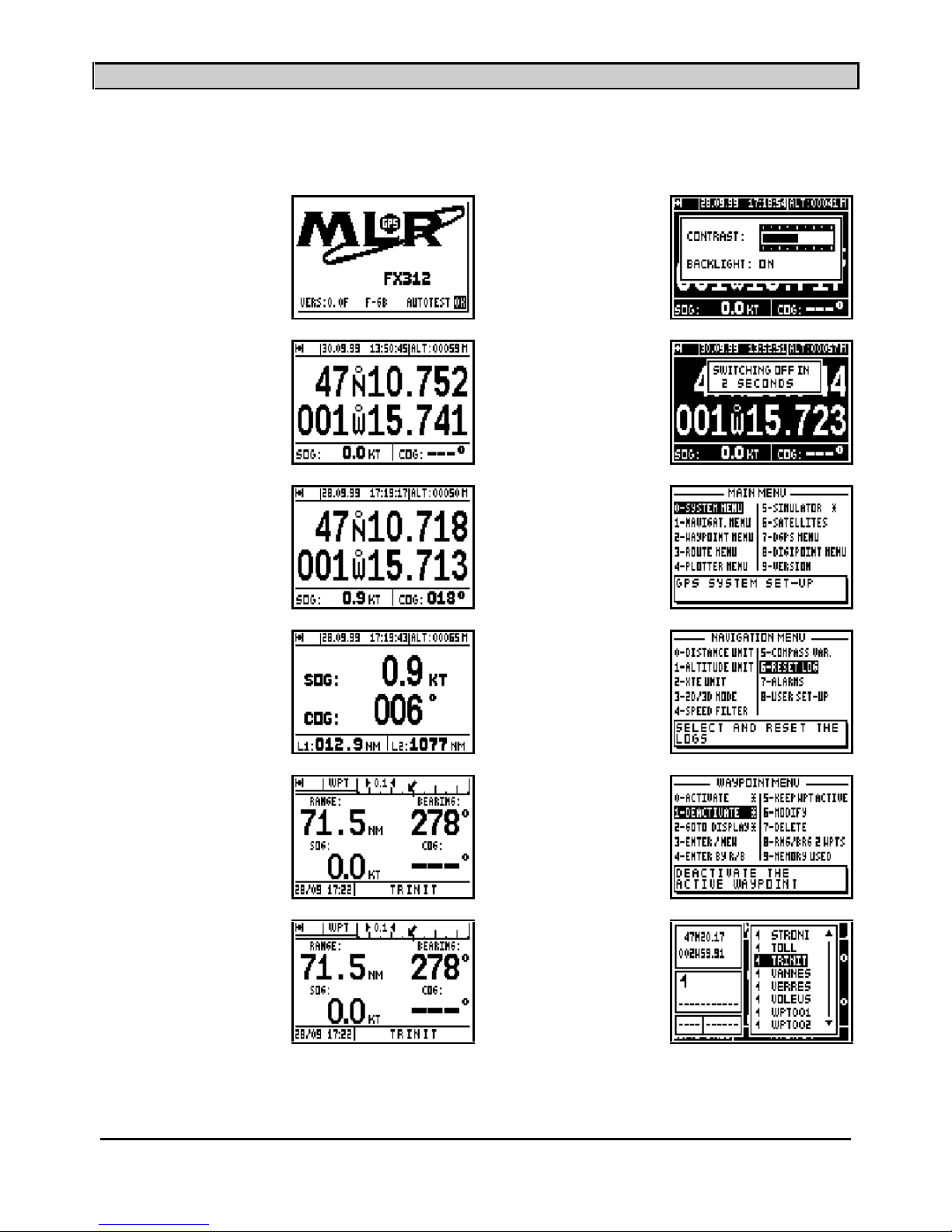
4 – GENERAL PROCEDURES USING THE KEYBOARD
Key
Function or action
Key
Function or action
PWR
PWR
From every function or
display
Ex
ample : POS
PWR
For 3 seconds
Pos
Menu
Nav
Menu
GoTo
Wayoint
Menu
GoTo
Waypoint
9
WXY
List
Page 50
FX312 & FX412 VERSION 2.0
MLR ELECTRONIQUE
50
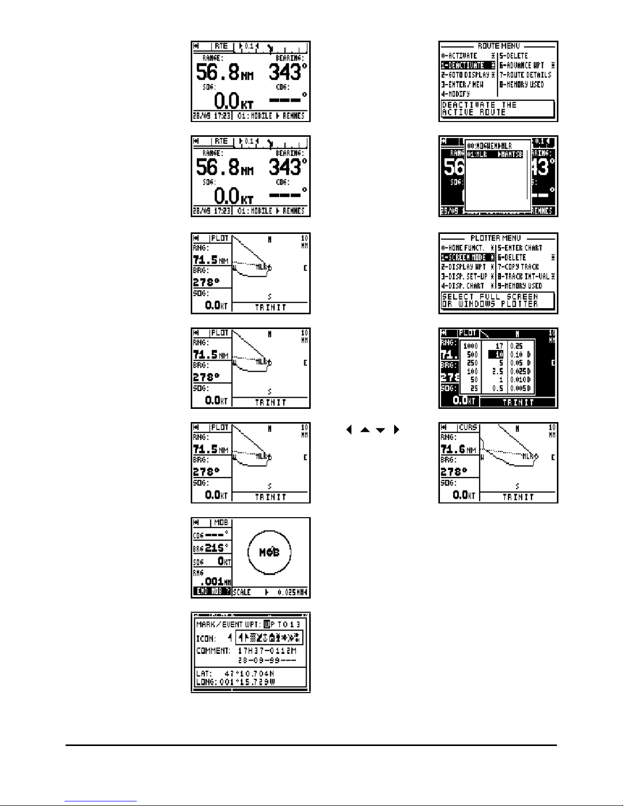
GoTo
Route
Menu
GoTo
Route
9
WXY
List
Plot
Menu
Plot
7
PRS
Zoom
Plot
Mark/Mob
One press in the MOB
mode
Enter
To stop the MOB
function
Mark/Mob
One press in the MOB
and MARK mode
Enter
To validate the event
waypoint
Page 51
FX312 & FX412 VERSION 2.0
MLR ELECTRONIQUE
51
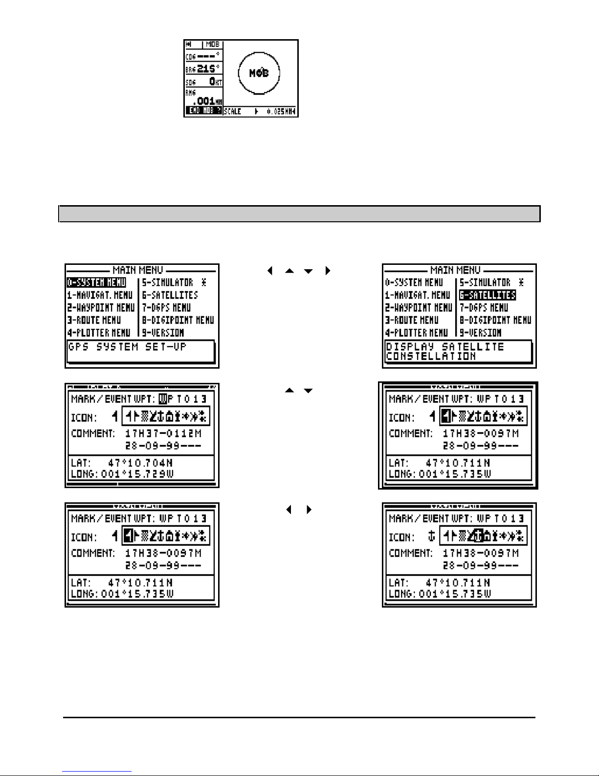
Mark/Mob
At least 3 presses in
the MOB and MARK
mode
Enter
To stop the MOB
function
Note: From the POSITION, SYSTEM MENUS, NAVIGATION, WAYPOINT, ROUTE or
PLOTTER functions, one press on the
Menu
key gives you access to the MAIN MENU. MENUS
with options denoted by a star return you directly to the function menu.
5 – USE OF 'ARROWS
' KEYS AND ENTER
Vertical and horizontal
movement of the cursor in a
MENU or option window
Vertical movement of the
cursor in an options window
or in a list
Horizontal movement to
select a parameter in a
line of op
tions within a window
Page 52
FX312 & FX412 VERSION 2.0
MLR ELECTRONIQUE
52
Highlight the option and scroll
through available choices
Key
Action
Enter
The
Enter
key allows you:
-
To validate a choice selected by the cursor.
-
To access to a MENU or data in a list
-
To finish and to validate
a data option
Note: If you wish to reject or cancel an option press one of the
Pos, Nav, GoTo, Plot
or
Menu
function keys.
____________________
6 – ABBREVIATIONS AND SYMBOLS
6.1. – ABBREVIATIONS AND SYMBOLS ON THE SCREEN
The symbol repres
enting a satellite indicates that the receiver calculates the
position
2D =
2 Dimensional
3D =
3 Dimensional
ALT =
Altitude
CURS =
Cursor
D =
Differential (DGPS)
RNG =
Range
DOP =
Dilution of the position
TTG =
Time to go
DER =
Distance to t
he End of the Route
ECP =
Error circular probability (estimated error)
FREQ R = Received frequency
FREQ T = Transmitted frequency
GPS =
Global Positioning System
ETA =
Estimated time of arrival
L1 =
Log 1
L2 =
Log 2
LAT =
Latitude
Page 53

FX312 & FX412 VERSION 2.0
MLR ELECTRONIQUE
53
LONG =
Longitude
M =
Message
MOB =
MAN OVER BOARD
PLOT =
Plotter
R/B =
Range and bearing
RTE =
Route
SIMU =
Simulator
SOG =
Speed over the ground
VTD =
Velocity to destination
WPT =
Waypoint
XTE =
Cross track error
6.2. – MEASUREMENT ABBREVIATIONS
Ft =
Feet
H =
Hour
KHz =
Kilohertz
KM =
Kilometre
KMH =
Kilometre/Hour
M =
Metre
MI =
Status mile
MIN =
Minute
NM =
Nautical mile
MPH =
Status Mile/Hour
KT =
Knot
° =
Degree
1 Nautical mile = 1852 Metres
1 Status mile = 1609 Metres
1 Foot = 0.3048 Metre
____________________
7 – INITIALISATION AND CONFIGURATION OF YOUR GPS
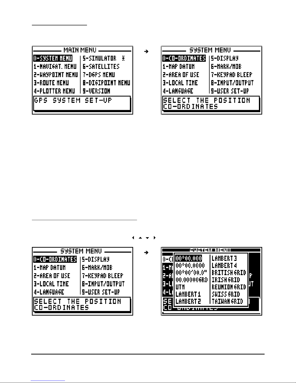
From the MAIN MENU you have access to the SYSTEM MENU (0) and the NAVIGATION
MENU (1). These MENUS allow you to set up your GPS to your own requirements. The
WAYPOINT MENU (2), ROUTE MENU (3) and the PLOTTER MENU (4) are used to manage
your waypoints, routes and tracks. These 3 MENUS are explained in the GOTO AND PLOT
functions. The DGPS MENU allows you to set up your receiver in DGPS mode (see chapter
B.9). The DIGIPOINT MENU allows you to enter easily waypoints, routes or chart outline from a
paper chart (see chapter B.10).
Page 54
FX312 & FX412 VERSION 2.0
MLR ELECTRONIQUE
54
7.1. – SYSTEM MENU
From the MAIN MENU, press key 0 (or select 0-SYSTEM MENU and press
Enter).
In the SYSTEM MENU the a
vailable options are:
-
0 - the choice of geographical co-ordinate
-
1 - the choice of map datums
-
2 - the selection of area of use
-
3 - the selection of time difference
-
4 - the selection of language
-
5 - the units of Altitude/ECP display for the P
OS and NAV functions
-
6 - the working mode of the MARK/MOB key
-
7 - the selection of audible BEEP for the keyboard
-
8
- the configuration of data input and data output (NMEA)
- 9 -
display summary of User Set Up options (SYSTEM MENU)
Note: The window
situated at the bottom of the screen explains the selected option.
7.1.1 – GEOGRAPHICAL CO-ORDINATES
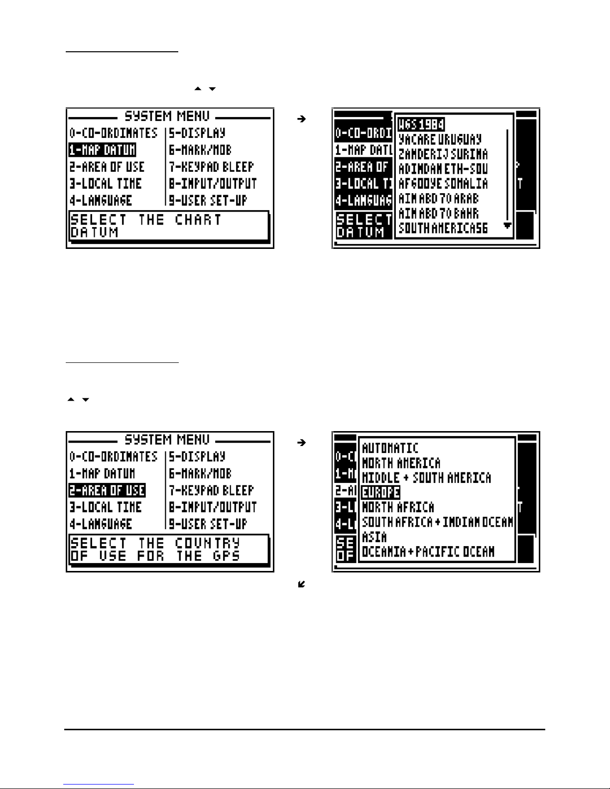
From the SYSTEM MENU, press the key 0 (or select 0-CO-ORDINATES and press
Enter
).
Select the type of co-ordinates using the
arrow keys and press Enter
.
Page 55
FX312 & FX412 VERSION 2.0
MLR ELECTRONIQUE
55
7.1.2 – MAP DATUMS
From the SYSTEM MENU, press the key 1 (or select 1-MAP DATUM and press
Enter
). Select
the map datum using the
arrow keys and press
Enter
.
To select the right format, identify the map datum used on your p
aper chart and check Annexe 2
where you will find the list of the available Map Datum formats for the receiver.
Advice: For UK use formats OSGB 36. For the rest of the world you can use by default the
datum's WGS -
72 or WGS - 84.
7.1.3 – AREA OF USE
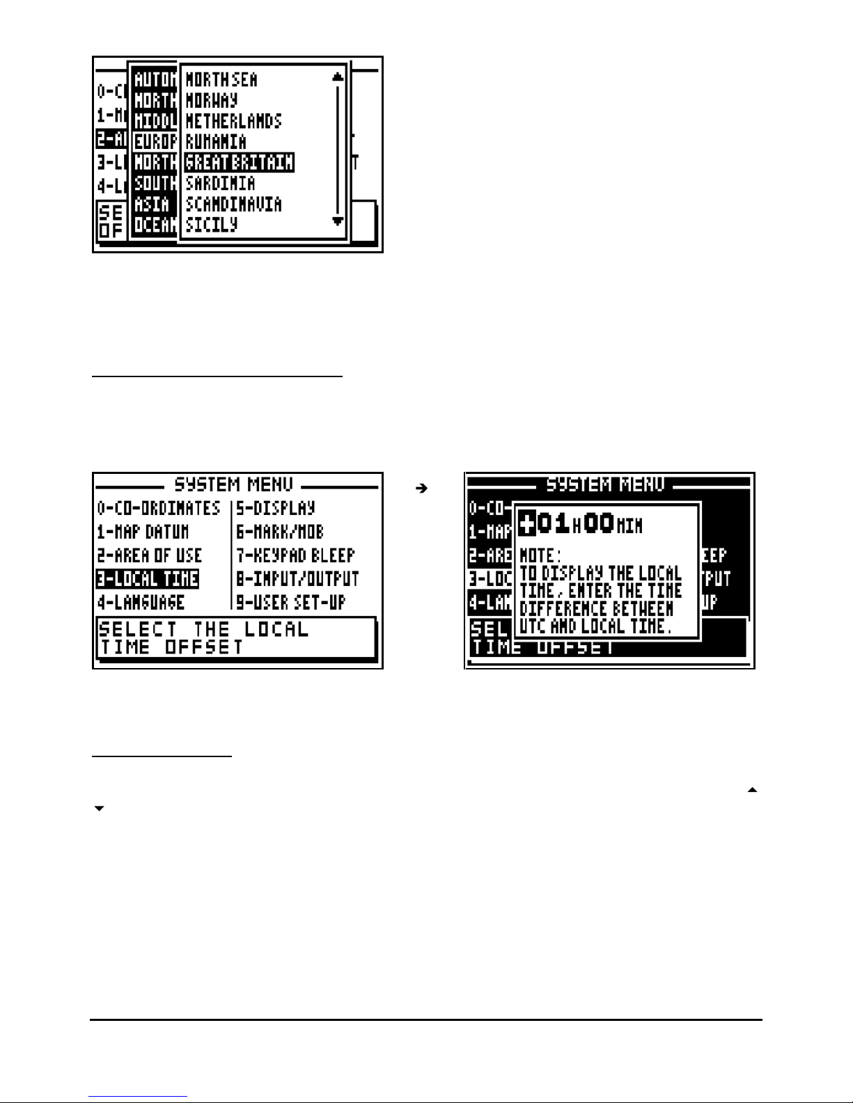
From the SYSTEM MENU, press key 2 (or select 2-AREA OF USE and press
Enter
. Using the
arrow keys, first select the Continent and press
Enter
, then select the country or the zone
where you use your GPS and press
Enter to confirm
.
Page 56
FX312 & FX412 VERSION 2.0
MLR ELECTRONIQUE
56
Tip: By selecting the Country of use it allows your GPS to find its position faster than the
automatic mode. When you change Country it is imperative to re-select your area of use or
select the automatic mode.
7.1.4 – LOCAL TIME DIFFERENCE
From the SYSTEM MENU, press key
3 (or select 3-LOCAL TIME and press
Enter
). If
necessary use the key 1 to change the sign from + to - then amend the time difference with the
help of the numeric keys and press Enter
to validate.
Tip: For UK the time difference is zero hour in the winter and plus one hour in summer.
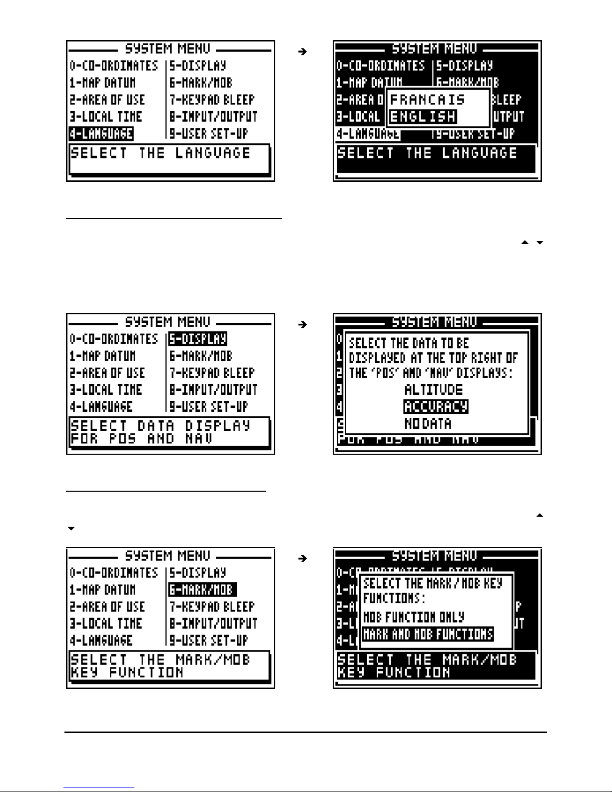
7.1.5 – LANGUAGE
From the SYSTEM MENU, press key 4 (or select 4-LANGUAGE and press
Enter
). Use the
arrow keys to select the language required and press
Enter
to confirm.
Page 57
FX312 & FX412 VERSION 2.0
MLR ELECTRONIQUE
57
7.1.6 – ALTIT
UDE / ACCURACY DISPLAY
From the SYSTEM MENU, press key 5 ( or select 5-DISPLAY and press
Enter
). Use the
arrow keys to select the display mode required and press
Enter
.
The selected information will be displayed in the top right of the screen in the POSITION and
NAVIGATION functions.
7.1.7 – MARK / MOB KEY FUNCTIONS
From the SYSTEM MENU, press key 6 (or select 6-MARK/MOB and press
Enter
). Use the
arrow keys to select the working mode required and press
Enter
.
Page 58
FX312 & FX412 VERSION 2.0
MLR ELECTRONIQUE
58
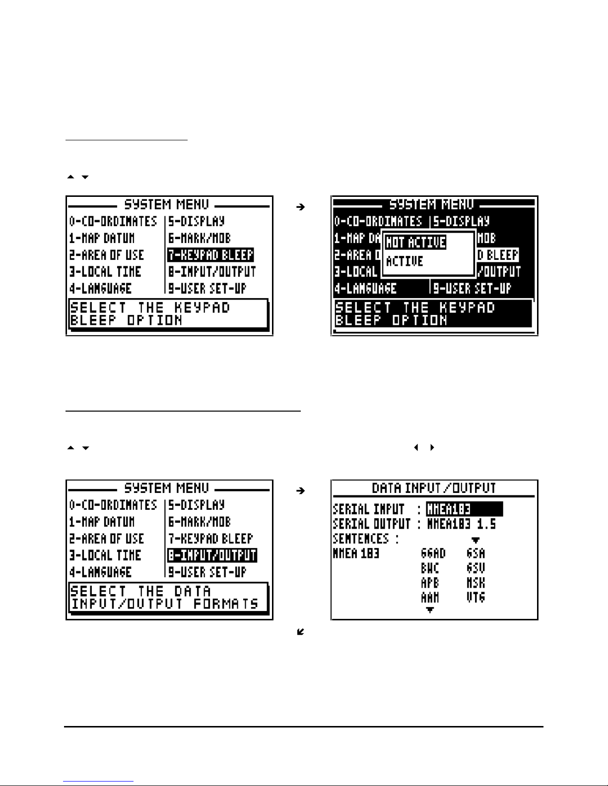
MOB function = A single press on the MARK/MOB key is sufficient to activate the MAN OVER
BOARD function (MOB).
MARK and MOB function = A single press activates the MARK (EVENT / WAYPOINT) function
and at least three presses activate the MAN OVER BOARD function (MOB).
7.1.8 – KEYPAD BLEEP
From the SYSTEM MENU, press key
7 (or select 7-KEYPAD BLEEP and press
Enter
). Use the
arrow keys to select the mode required and press
Enter
.
Select active to activate the keypad bleep function, the receiver will now bleep with every key
press.
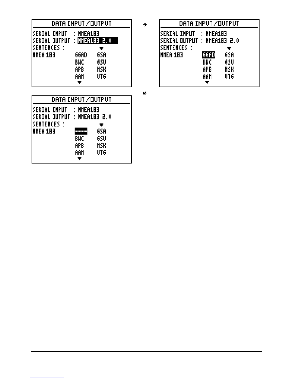
7.1.9 – DATA INPUT / DATA OUTPUT (NMEA)
From the SYSTEM MENU, press key 8 (or select 8-INPUT/OUTPUT and press
Enter
). Use the
arrow keys to move the cursor in the options window. Use the
arrow keys to select
the required conf
igurations and the press
Enter
to confirm.
Page 59
FX312 & FX412 VERSION 2.0
MLR ELECTRONIQUE
59
Your GPS has a data input and a data output to communicate with the other equipment. The
data input is used to receive differential correction or loading waypoints and routes from a
P.C.
The data output is used to transmit the position, navigation information, waypoints and routes to
a: P.C., automatic pilot, plotter and radar.
Your receiver allows you to select the NMEA sentences to be transmitted. To de-select a
sentence select 4
dashes (
- - - -).
You will find specifications of the different formats of communication in ANNEXE 1.
Advice: To use your receiver with PMS WAYPOINTS & ROUTES software for downloading
waypoints and routes to a PC, select the format WPTS + RTES for the data output. Select the
format CHART OUTLINE to download a chart outline from your receiver to the PC and select
the format TRACK to download the track from your receiver to the PC. To load datas from a PC,
make sure the NMEA183 is selected for the serial i
nput.
Page 60
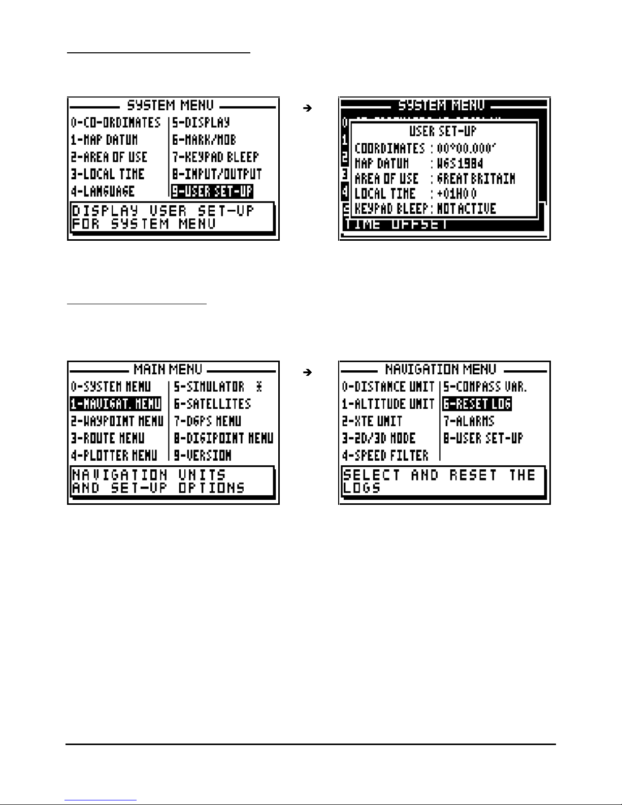
FX312 & FX412 VERSION 2.0
MLR ELECTRONIQUE
60
7.1.10 – USER SET-UP SUMMARY
From the SYSTEM MENU, press key 9 (or select 9
-USER SET UP and press
Enter).
Information that is not directly visible is displayed in the SYSTEM MENU user set up.
7.2. – NAVIGATION MENU
From MAIN MENU, press key 1 (or select 1-NAVIGAT.MENU and press
Enter
). It is also
possible to reach this MENU from the NAVIGATION function by pressing the
Menu
key.
In the NAVIGATION MENU the options available are:
-
0 - select the distance and speed units
-
1 - select the altitude unit
-
2 - select the cross track error unit
-
3 - select 2D/3D mode
-
4 - select the speed filter rate
-
5 - set compass variation
-
6 - reset trip logs
-
7 - set up the alarms (arrival, anchor or XTE)
- 8 -
display summary
of navigation user options
Note: The window situated in the bottom of the screen explains the selected option.
Page 61
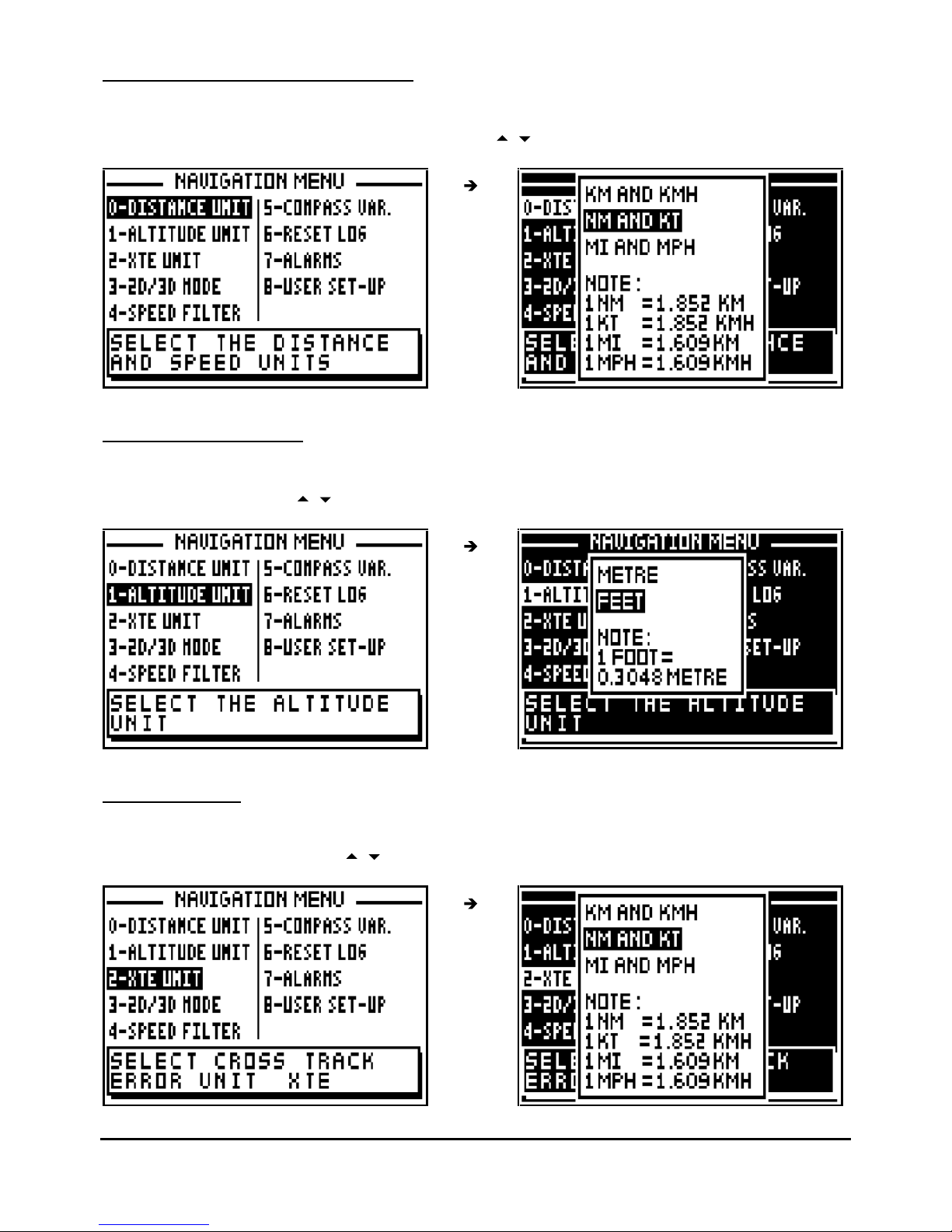
FX312 & FX412 VERSION 2.0
MLR ELECTRONIQUE
61
7.2.1 – DISTANCE AND SPEED UNITS
From the NAVIGATION MENU, press the key 0 (or select 0-DISTANCE UNIT and press
Enter
).
Select the distance u
nit and speed units using the
arrow keys and press Enter
.
7.2.2 – ALTITUDE UNITS
From the NAVIGATION MENU, press key 1 (or select 1-ALTITUDE UNIT and press
Enter
).
Select the unit using the
arrow keys and press
Enter
.
7.2.3 – XTE
UNIT
From the NAVIGATION MENU press key 2 (or select 2-XTE UNIT and press
Enter
). Select the
cross track error unit using the
arrow keys and press
Enter
.
Page 62
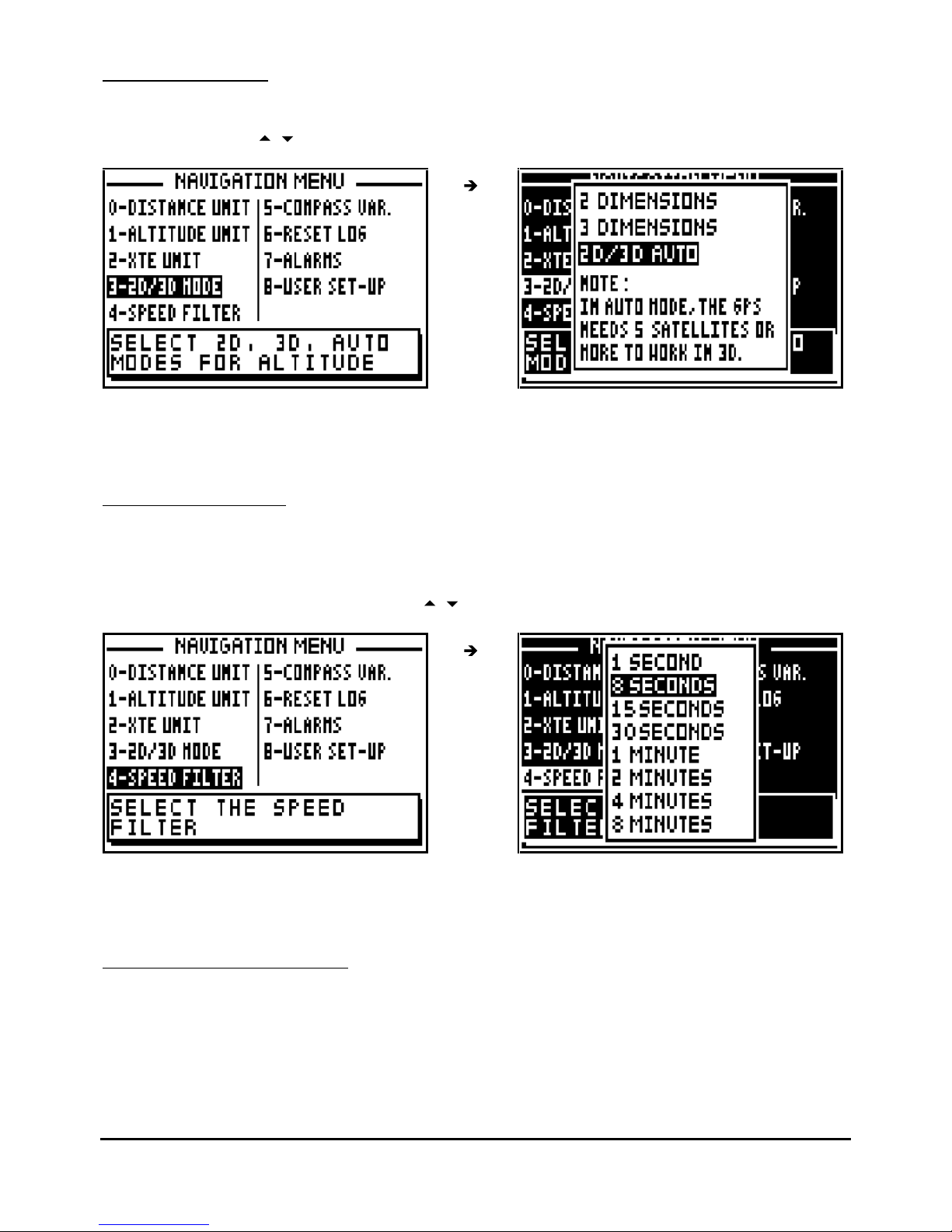
FX312 & FX412 VERSION 2.0
MLR ELECTRONIQUE
62
7.2.4 – 2D/3D MODE
From the NAVIGATION MENU press key 3 (or select 3-2D/3D MODE and pre
ss
Enter
). Select
the mode using the
arrow keys and press
Enter
.
Tip: For marine use, select the 2D mode and enter your altitude, which is the height of the
antenna above sea level.
7.2.5 – SPEED FILTER
Filtering or smoothing increases the
accuracy of the speed readout.
From the NAVIGATION MENU, press key 4 (or select 4-SPEED FILTER and press
Enter
).
Select the speed filter required using the
arrow keys and press
Enter
.
Tip: For a fast vehicle (e.g. car) use a short constant and for a slow vehicle (e.g. boat) use a
longer constant.
7.2.6 – COMPASS VARIATION
The bearing and course are referenced to true north. To reference them to the magnetic north it
is necessary to enter the compass variation. The magnetic variation is generally indicated on
the navigation chart.
Page 63
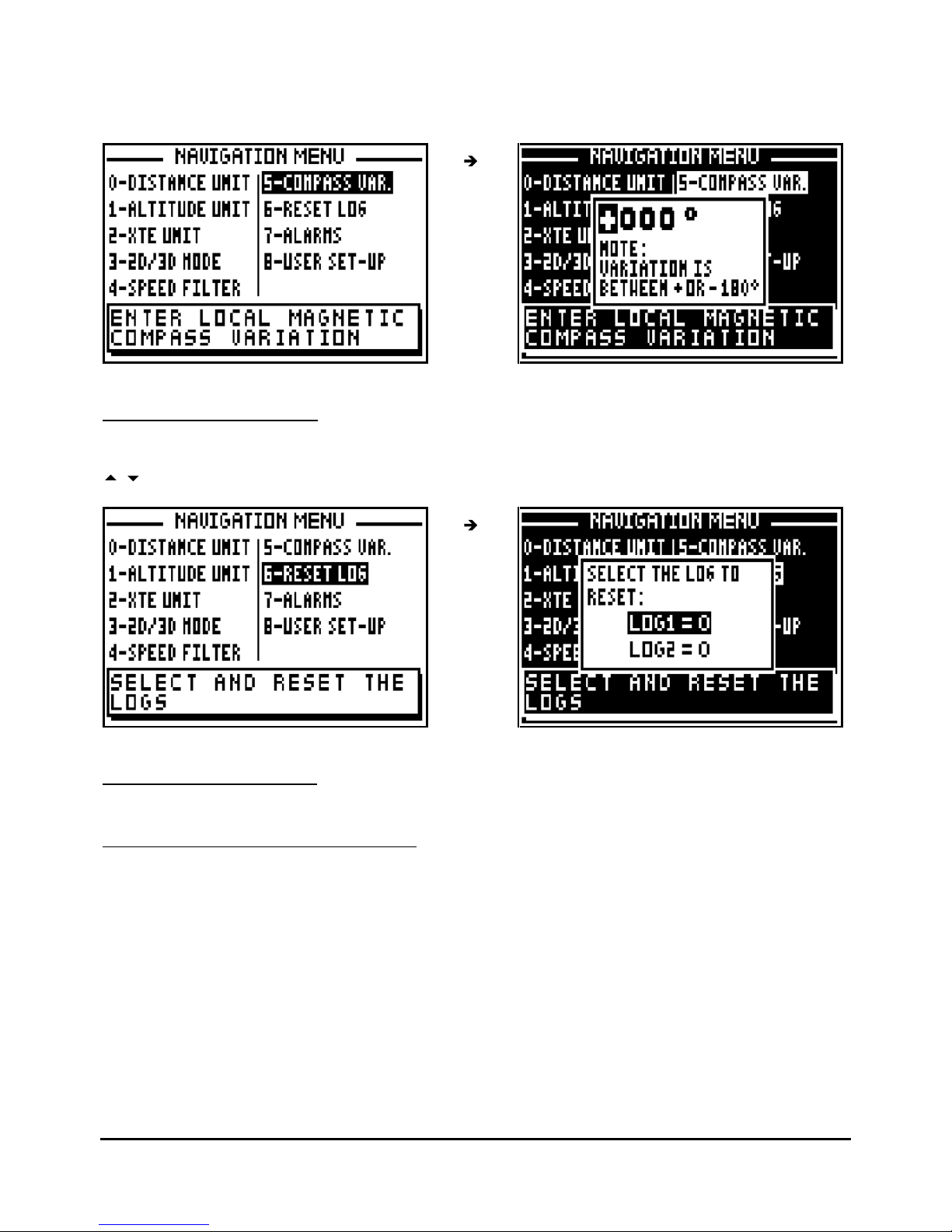
FX312 & FX412 VERSION 2.0
MLR ELECTRONIQUE
63
From the NAVIGATION MENU, press key 4 (or select 4-COMPASS VAR. and press
Enter
). If
necessary use the 1 key to change the sign from + to -, then enter the compass variation using
the numeric keys and press
Enter to validate.
7.2.7 – RESET TRIP LOGS
From the NAVIGATION MENU, press key 5 (or select 5-RESET LOG and press
Enter
). Use the
arrow keys to select the log to reset (LOG1 or LOG2) and press Enter
.
7.2.8. – SET THE ALARMS
7.2.8.A – WAYP
OINT ARRIVAL ALARM
The arrival alarm sounds to warn you of your arrival at your destination waypoint or to inform
you that you have completed the leg of a route.
The adjustable options are:
ON/OFF = On Off of the audible alarm (the visual alarm and the passage to the following
waypoint in the ROUTE function are always active).
MODE = the audible alarm gives out BEEPS for a duration of 10 seconds or for an unlimited
time until the user presses a key on the keyboard.
Page 64
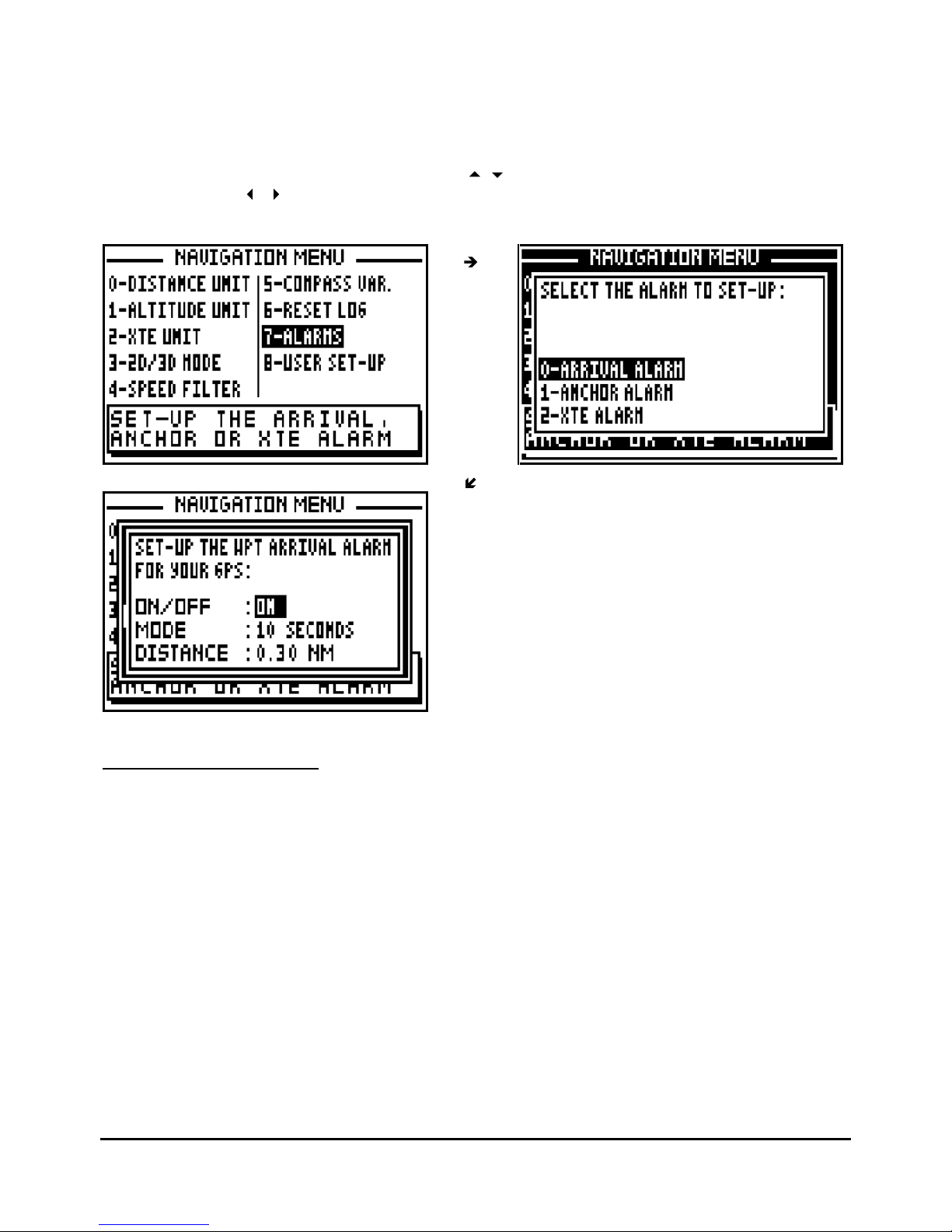
FX312 & FX412 VERSION 2.0
MLR ELECTRONIQUE
64
DISTANCE = it is the radius from a waypoint that you wish the alarm to sound. The visual
alarm and the audible alarm are activated when the vessel enters the circle, (this circle is
determined by the alarm radius selected).
From the NAVIGATION MENU, press key 7 (or select 7-ALARMS and press Enter), then press
the key 0 to select ARRIVAL ALARM. Use the
arrow keys to move the cursor in the option
window. Use the
arrow keys to select alarm ON/OFF and the mode required. Use the
numeric keys to enter the distance. Once all parameters ar
e configured, press
Enter
to validate.
7.2.8.B – ANCHOR ALARM
The anchor alarm is used to warn you of your drift in relation to a reference waypoint. The
reference waypoint is the active waypoint of the GOTO WAYPOINT function. Each time the
distance from the reference waypoint is bigger than the distance fixed in the set up, the alarm
will sound to inform you about your drifting.
The adjustable options are:
ON/OFF = On Off of the audible alarm.
MODE = the audible alarm gives out BEEPS for a duration of 10 seconds or for an unlimited
time until the user presses a key on the keyboard.
DISTANCE = it is the radius from a waypoint that you wish the alarm to sound. The visual alarm
and the resonant alarm are released when the vessel exits the circle, (this circle is determined
by the alarm radius selected).
Page 65
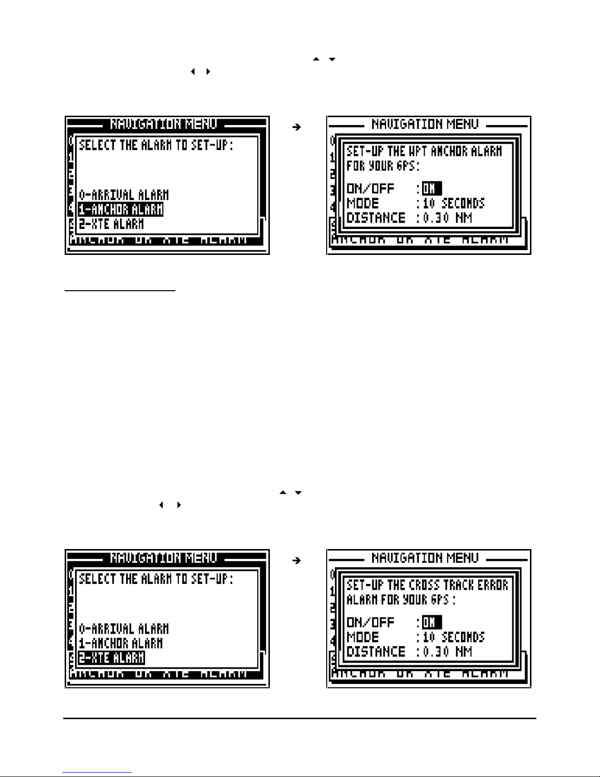
FX312 & FX412 VERSION 2.0
MLR ELECTRONIQUE
65
From the NAVIGATION MENU, press key 7 (or select 7-ALARMS and press Enter), then press
the key 1 to select ANCHOR ALARM. Use the
arrow keys to move the cursor in the
options window. U
se the
arrow keys to select alarm ON/OFF and mode required. Use the
numeric keys to enter the distance. Once all parameters are configured press
Enter
to validate.
7.2.8.C – XTE ALARM
The XTE alarm is used to warn you of your drift from the direct route to a reference waypoint.
The direct route is the line from your position when you launched the GOTO function to the
waypoint. Each time the distance is bigger than the distance fixed in the set up, the alarm will
sound to inform you about yo
ur drifting.
The adjustable options are:
ON/OFF = On off of the audible alarm.
MODE = the audible alarm gives out BEEPS for a duration of 10 seconds or for an unlimited
time until the user presses a key on the keyboard.
DISTANCE = it is the radius from a distance that you wish the alarm to sound. The visual alarm
and the resonant alarm are released when the vessel is out of this range.
From the NAVIGATION MENU, press key 7 (or select 7-ALARMS and press Enter), then press
the key 2 to select XTE ALARM. Use the
arrow keys to move the cursor in the options
window. Use the
arrow keys to select alarm ON/OFF and mode required. Use the
numeric keys to enter the distance. Once all parameters are configured press
Enter
to validate.
Page 66
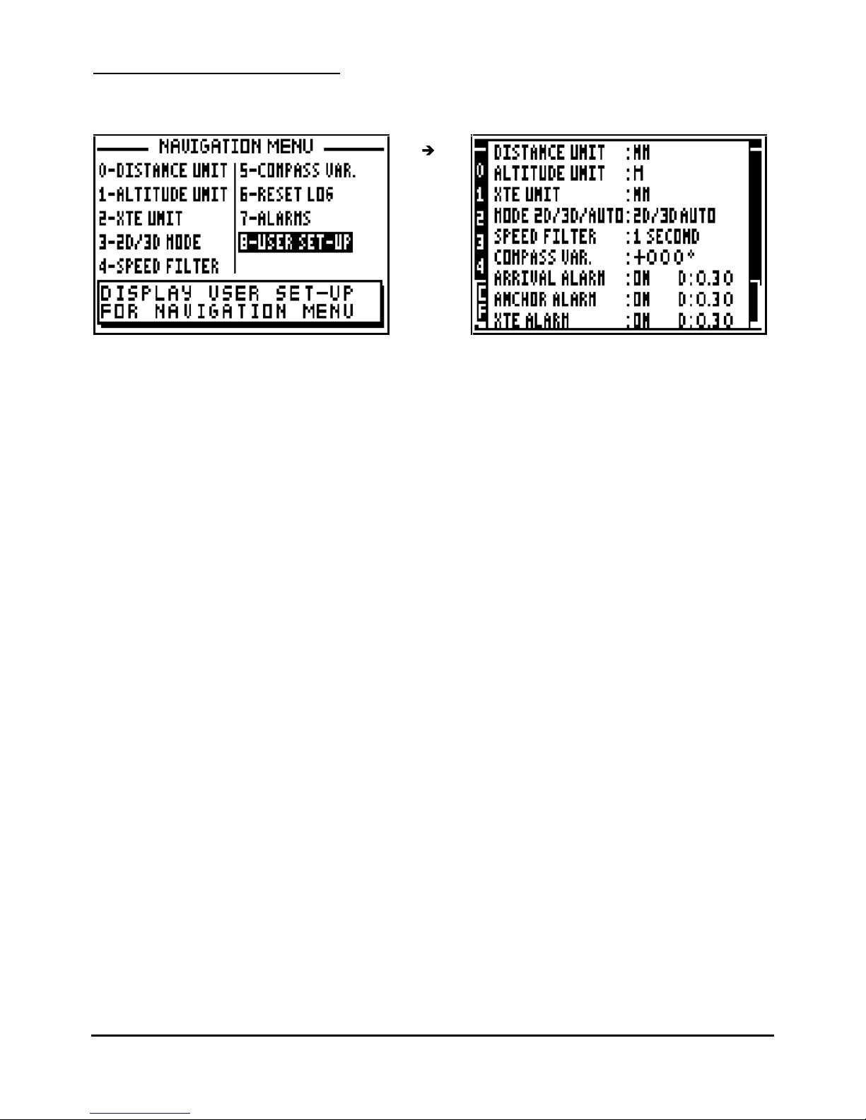
FX312 & FX412 VERSION 2.0
MLR ELECTRONIQUE
66
7.2.9 – USER SET-
UP SUMMARY
From the NAVIGATION MENU press key 8
(or select 8-USER SET-UP and press
Enter).
Page 67

FX312 & FX412 VERSION 2.0
MLR ELECTRONIQUE
67
D –
DESCRIPTION OF THE EQUIPMENT AND SPECIFICATIONS
1 – CONTENTS OF FX312
-
1 receiver case.
- 1 antenna with 10 metres of coaxial cable and TNC p
lug.
-
1 power supply cable with fuse and data input/output.
- 1 pair of support brackets with 2 trunnion knobs and 2 rubber washers
-
4 fixing screws
-
1 spare fuse
-
1 User’s Manual
-
1 guarantee card
-
1 Quick Reference Card
____________________
2 – CO
NTENTS OF FX412
-
1 receiver case.
-
1 GPS/DGPS antenna with 10 metres of coaxial cable and TNC plug.
-
1 0.85 metre whip.
-
1 power supply cable with fuse and data input/output.
-
1 1 metre white cable for antenna reference.
-
1 1 metre yellow/green cab
le for connection of the receiver case with the ground.
-
2 screws, 2 washers and 2 fan washers.
-
1 pair of support brackets with 2 trunnion knobs and 2 rubber washers.
-
4 fixing screws.
-
1 spare fuse.
-
1 User’s Manual.
-
1 guarantee card.
-
1 Quick Re
ference Card.
____________________
3 –
COMMUN SPECIFICATIONS OF THE FX312 & FX412
Main functions :
. Direct Access™ (direct access to POS, NAV, GOTO, PLOT, MARK/MOB and MENU
functions)
. Latitude, longitude with definition of the 1/10000 of minute (18cm).
. Altitude, accuracy, date and time.
. 14 types of co-ordinates, UTM, Lambert, Switzerland
Grid, UK Grid.
. 115 map datum's Europe 50, WGS 84, WGS72.
. Speed and course over the ground.
Page 68

FX312 & FX412 VERSION 2.0
MLR ELECTRONIQUE
68
. Velocity to destination.
. Two logs.
. 500 waypoints with name by 6 alphanumeric characters, comment of 22 characters and icon
representation for the plotter
function.
. 20 reversible routes of 20 waypoints with total length and details of route and waypoint
advance.
. Direct Access™ to the list of waypoints or routes with the List key
. Range and bearing to the destination waypoint.
. Range and bearing between 2 waypoints.
. Time to go.
. Estimated time of arrival.
. Cross track error.
. Distance to the end of the ro
ute.
. Direct Access™ to the MOB (Man Over Board) function
. Direct Access™ to the MARK (Event / Waypoint) function.
. DATA mode for the GOTO function, large characters for range and bearing to the waypoint,
speed and course over the ground.
Bargraph for the cross track error with automatic scales.
. 3 graphic representations of the GOTO function: Compass, 3D road and Radar.
. Graphic display of satellite constellation with signal strength bargraph .
. Enter a waypoint by its range and bearing in relation to another waypoint or vessels current
position
. Arrival, anchor and cross track error alarms which can be set up. .
. Simulator mode.
Plotter Functions :
. Full screen or multi-windows display.
. Personalisation of navigation information
in multi windows mode
. 250 track and 250 chart outline points
. Track interval selectable from 10 metres to 100 kilometres.
. Zoom with Direct Access™ (by the Zoom key scales from 5m to 1000 Km).
. Home function.
. Display of the 500 waypoints with th
eir icons.
. Display of the direct track to the destination waypoint.
. Display of the active route.
. Direct Access™ to a waypoint by pressing the key .
. PMS function to enter a chart outline using Yeoman Plotter
General features :
. Receiver L1 (15
75.42 MHz) receiver 12 satellites with parallel technology
. Horizontal position and speed accuracy
-
25 metres RMS (2D), 1Km/hour RMS with SA code.
-
2 to 5 metres, 0.1Km/hour in differential RTCM 104 mode.
. Acceleration: 3g.
. Update rate: 1 second.
. T
ime to fix:
-
Reacquisition 4 seconds.
- Up to 3 hours off: 30 seconds.
- Up to 24 hours off: 90 seconds.
-
World-wide cold start: 3 minutes.
. Screen: FSTN screen with backlight 91 x 59 mm.
Page 69
FX312 & FX412 VERSION 2.0
MLR ELECTRONIQUE
69
. Keypad: complete illuminated keypad with 19 tactile keys with
4 arrow keys.
. Memory: FlashRom technology guaranteeing the safeguard of navigation information,
waypoints, routes etc., backup lasts up to 100 years no lithium battery
. Dimensions of the receiver: 198 x 101 x 63 mm.
. Dimensions of antenna: 113 x 75
mm + whip antenna (0.85 m) for the FX412.
. Operating temperature: -10°C to +60°C.
. Storage temperature: -20°C to + 70°C.
. Power supply: 10 to 36 volts DC.
. Waterproof: IPX6 IEC 529 norm
FX312
FX412
. Weight
400 grams
450 grams
. Consumption w/o backlight
1.5 watts
2.4 watts
. Consumption with backlight 2.0 watts
3.0 watts
. Electromagnetic compatibility: According to the IEC norm 945 second and third publication.
. Data input and data output :
. Serial output : 1 RS422 + 1 RS232 ; format NMEA180, NMEA182, NMEA183 V1.5,
NMEA183 V2.0, MLR, WPTS & RTES, CHART OUTLINE, TRACK.
. Serial input : 1 RS232 ; format NMEA183, RTCM104.
* * ATTENTION: Do not expose to direct sunlight.
4 –
PARTICULAR SPECIFICATIONS OF THE FX412
DGPS FX412 specifications
. RTCM SC 104 V2.1 receiver.
. Frequencies : 281.5 to 325 KHz by step of 500 Hz,
Europe, Asian, Oceania and US range.
. Baud rate : 100 Bps and 200 Bps.
. Manual selection of the stations.
. Type : dual super heterodyne with MSK coherent detection.
. Adja
cent channel rejection +/- 500 Hz = 30 dB.
. central channel rejection +/-
10 Hz =
-3 dB.
Page 70
FX312 & FX412 VERSION 2.0
MLR ELECTRONIQUE
70
E – INSTALLATION INSTRUCTIONS
1 – RECEIVER CASE
The receiver can be wall mounted, fitted to your chart table or under a shelf using the versatile
multi-position
brackets. The receiver can also be flush mounted by using the flush mounting kit
available in option.
POWER SUPPLY
The FX312 and FX412 use 10 to 32 Volt DC supply. They are protected against reverse
polarity. A fuse is integrated into the power supply lead. Connect the cable as detailed below,
connect the red wire to the positive (+) and the blue wire to the negative (-).
DATA OUTPUT
The FX312 and FX412 have two data outputs: RS232 output for direct connection with a P.C.
and an RS422 (NMEA) output fo
r navigation devices (autopilot, radar, plotter,…).
DATA INPUT
The FX312 and FX412 have one data input for loading waypoints from a P.C. or for the
connection with an external differential beacon receiver (DGPS).
CONNECTION WITH A P.C. AND WITH THE MLR DF300 DGPS RECEIVER
FX312/FX412 Wiring
FX312/FX412 Designation
DF300 Wiring
P.C. pins
Blue
-
0 Volt
Blue
Red
+10 to 36 Volts DC
Red
Brown or orange
Reference RS422 (NMEA OUT)
Yellow
Yellow
Output RS422 (NMEA OUT)
Green
Green
Reference RS232
Bl
ack
5
Black
Input RS232
White
3
White
Output RS232
2
The pin numbers for the P.C. SUBD connector (9 pin) are in the above table.
To interface the FX312/FX412 to an autopilot, plotter, sounder or radar, connect the brown (or
orange) wire and the yello
w wire to the NMEA input of the external device.
Earthing the FX412 (only for the FX412)
Advice:
To obtain optimum reception of DGPS signal, it is recommended that where a earth
(ground) connection exists on a vessel it be connected to screw terminal on the rear of the
equipment via the green/yellow wire provided, taking the shortest route possible. Do not
hesitate to cut the earth wire to obtain the shortest length. See diagram.
Page 71
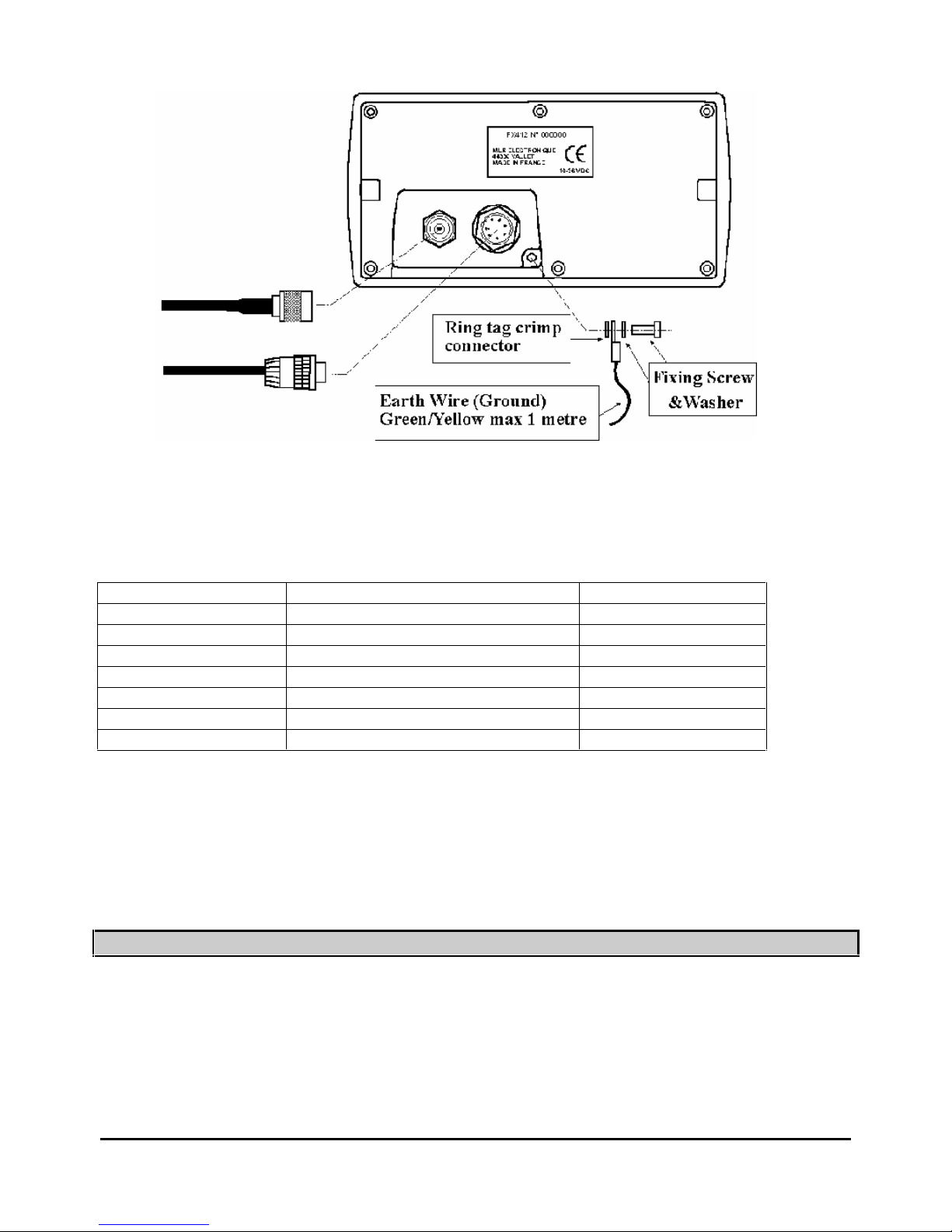
FX312 & FX412 VERSION 2.0
MLR ELECTRONIQUE
71
CONNECTION WITH a YEOMAN TYPE PLOTTER
To construct your electronic chart from a YEOMAN plotter connect it to your FX312 as detailed
below:
FX312/FX412 Wiring
FX312/FX412 Designation
Yeoman Wiring
Blue
- 0 Volt
Blue
Red
+10 to 36 Volts DC
Red
Brown or orange
Reference RS422 (NMEA OUT)
Yellow
Outpu
t RS422 (NMEA OUT)
Green
Reference RS232
Black
Black
Input RS232
Green
White
Output RS232
White
Connect the 2 black wires of YEOMAN with the two blue wires.
____________________
2 – SITING THE ANTENNA
The antennas of the FX312 and the FX412 are different. Therefore, you will find hereafter 2
specific paragraphs for each antenna model.
Page 72

FX312 & FX412 VERSION 2.0
MLR ELECTRONIQUE
72
2.1.- FX312 ANTENNA
The antenna coax cable must not exceed 10 metres in length. It may however be shortened to
suit. The antenna must have a clear view of
the horizon all round for best reception results.
-
For sailboats mount the antenna on the pushpit.
- For motorboats mount the antenna on the cabin roof
When there is a radar, the antenna must be sited above the radar scanner
Contrary to previous MLR antennas it is now possible to cut the cable to shorten it. The
minimum length is 1 meter.
The coaxial cable must take the shortest route to the display unit whilst avoiding any other
power or signal cables. The TNC plug is connected on to the antenna cable at time of
manufacture to ensure a good quality connection.
2.2.- FX412 ANTENNA
The antenna is best sited well above the main structure of the vessel, clear of all surrounding
objects, especially all transmitting aerials.
Fix the counterpoise of the antenna (white cable) to the antenna with the use of the screw and
washers provided. The counterpoise cable must be vertical for 80% of its length. Secure the
cable using cable ties or insulation tape to stop movement. The counterpoise cable of the
ante
nna must not be placed inside a metallic tube or mast and not connected to any earth or
metallic part of the vessel.
Where radar is fitted aboard the vessel the antenna must be sited above the scanner and well
clear of the radar beam.
Advice: The antenn
a can be installed on any 1 inch 14 TPI bracket.
N.B. Suitable non-metallic 14TPI extension poles and a variety of brackets are available from
your local dealer.
The coaxial cable must take the shortest route from the antenna to the display unit, whilst
avoiding any other power or signal cables The TNC antenna plug is connected to the cable at
the time of manufacture to ensure a good quality connection
The antenna coaxial cable must not exceed 10 meters in length. It may however be shortened
to suit th
e installation.
Contrary to previous MLR antennas it is now possible to cut the cable and shorten it. The
minimum length is 1 metre, in this event a new TNC connector must be obtained and correctly
fitted. (It is not possible to re-use the factory fitted
one.)
Note: Only the whip antenna provided with the FX412 part no. ACC026 must be used with the
antenna assembly.
Page 73
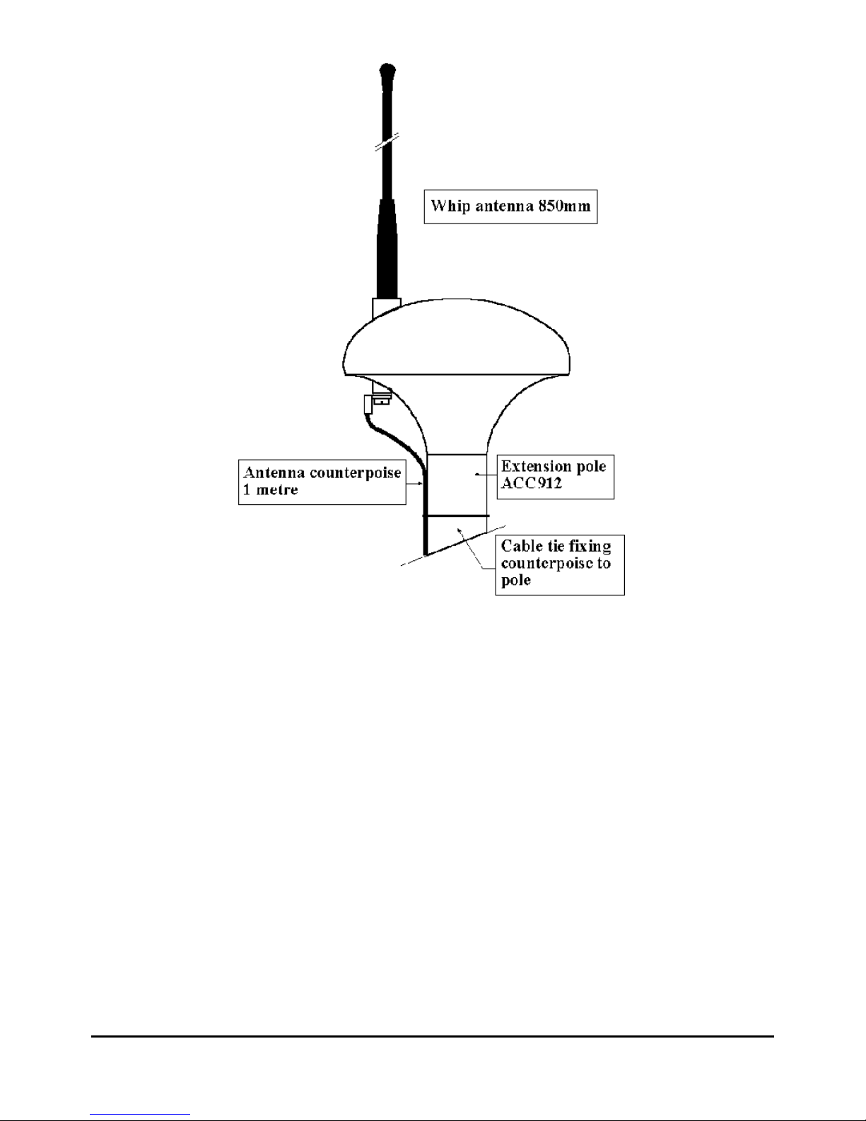
FX312 & FX412 VERSION 2.0
MLR ELECTRONIQUE
73
____________________
Page 74

FX312 & FX412 VERSION 2.0
MLR ELECTRONIQUE
74
3 – PROCEDURE FOR ELIMINATION OF INTERFERENCE (ONLY FOR FX412)
Frequencie
s used to transmit the differential corrections are situated in the 300 kHz band (long
waves). This frequency band is very sensitive to interference that can be generated by the
electric or mechanical devices on board the vessel. To obtain the best results from your FX412,
we advise that you verify the good reception of the differential signal.
Where interference or electrical noise interferes with DGPS reception, we advise that you carry
out the procedures given below to try to eliminate the problem.
3.
1. – VERIFICATION OF DIFFERENTIAL SIGNAL RECEPTION
For this operation only,
ALL
equipment on board must be switched off with the exception of the
FX412 which must be switched on.
From the GENERAL MENU, press key 7 (or select 7–DGPS MENU and to press
Enter
).
Choose and program the frequency and the Baud rate of the station nearest to your position
(see paragraph B.9.1). Read on the left of the screen the reception level of the differential signal
(a good signal = ¾ of the black bargraph) and the error rat
e of received information (it should be
zero = white bargraph). In bottom of the screen read the identification number of the DGPS
station together with its status and the list of satellites corrected.
Note the level of reception of the differential signal as well as the success rate, and proceed to
the following paragraphs.
3.2. – DETECTION OF THE INTERFERENCE PRESENT
To see if any equipment causes DGPS interference you need to switch on all electric devices
on board, then start the engines. You must start by switching on one item, waiting for 2 minutes
then checking the DGPS SIGNAL LEVEL & % ERROR received. If there is no change to the
SIGNAL LEVEL & % ERROR, repeat the procedure with the next item. Finally start the
engine(s) and once again check the levels. If there is no variation then interference is not
present and your FX412 installation is perfect. If the SIGNAL LEVEL decreases substantially or
the % ERROR increases substantially, go to paragraph 3.
3.3. – DETECTION OF THE NATURE OF INTERFERE
NCE
The best tool is an isolated 12 Volts battery, it permits the detection of the type of interference,
conducted interference, (conducted via the power supply), or radiated interference, (received by
the antenna). Connect the FX412 to the isolated 12 Volt battery (ensure that the ground, the
data output and input are completely disconnected) and repeat the procedure in paragraph 2.
If the interference ceases it is on the power supply, go to the next paragraph 4, if the
interference continue go directl
y to the paragraph 5.
Page 75
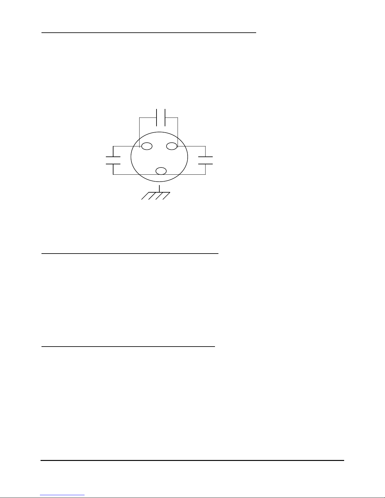
FX312 & FX412 VERSION 2.0
MLR ELECTRONIQUE
75
3.4. – SOLUTION TO INTERFERENCE ON THE POWER SUPPLY.
IF IN DOUBT CONTACT A LOCAL QUALIFIED MARINE ELECTRICAL ENGINEER BEFORE
PROCEEDING. For each device interfering with DGPS reception, put a 2 or 3 microfarad
suppression capacitor from the positive connection to the metal case of the device causing the
problem. Note: It may be necessary to put additional capacitors between positive and negative
and from negative to the case, which must be earthed (grounded)
N.B.: For engines equipped with alternators it is necessary to wire the 3 capacitors as shown in
the following diagram:
In difficult cases an isolated battery power supply may be the only solution.
3.5. – SOLUTION OF INTERFERENCE BY R
ADIATION
For every device interfering with the FX412, check the earth bonding of the device to the ships
ground connection.
If the engine is the source of interference, the construction of a low resistance, fine mesh cage
inside the engine compartment, bonded to the engine block should be considered. (Faraday
cage principle)
Try various sites for the antenna of the FX412.
3.6. – SOLUTION TO MECHANICAL INTERFERENCE
If the interference is caused only when the propeller is engaged in gear, it may be necessary to
earth (ground) the propeller shaft, utilising a set of shaft brushes.
_
+
 Loading...