

MLis MLB-Z4001 User Manual
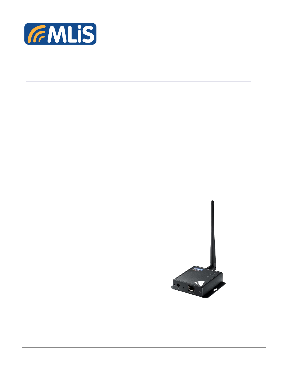
MLB-Z4001
Ethernet to 900 MHz
RF Modem
USER MANUAL
MLB-Z4001 Terminal User Guide 1 Rev 1.0

Information provided by Schmidt & Co., (HK) Ltd, (herein known as ‘the company’), is believed to
be accurate and reliable. However, the company assumes no responsibility for its use, nor any
infringement of patents or other rights of third parties, which may result from its use. No license is
granted by implication or otherwise under any patent rights of the company other than for circuitry
embodied in the company’s products. The company reserves the right to change the circuitry and
specifications at any time without notice. This document is subject to change without notice.
No part of this document may be reproduced or transmitted in any form or by any means,
electronic or mechanical, including but not limited to photocopying, recording, transmitting via fax
and/or modem devices, scanning, and/or information storage and retrieval systems for any
purpose without the expressed written consent of the company.
WARNING: The MLiS GSM Terminal is a RF product intended for interfacing and operating with
a host device. Local relevant RF regulations such as allowed frequencies and usage in
commercial flights must be observed. Safety instructions must be included in the manuals of the
host device. Schmidt & Co., (HK) Ltd assumes NO liability for customers, who fail to comply with
these precautions.
Service and Support
support.mlis@schmidtelectronics.com
Download Information
http://www.schmidtm2m.com/en/support_download.php
MLB-Z4001 Terminal User Guide 2 Rev 1.0

CONTENTS
1 INTRODUCTION ............................................................................................................................... 5
1.1 Description ................................................................................................................................ 5
1.2 Highlights .................................................................................................................................. 5
1.3 Functional Block diagram .......................................................................................................... 7
1.4 Main Features and Services ...................................................................................................... 8
1.4.1 Operating Modes ................................................................................................................... 8
1.4.2 Terminal Features and Electrical Specifications .................................................................... 9
1.5 Precautions ............................................................................................................................... 9
2 MECHANICAL DESCRIPTION ........................................................................................................ 10
2.1 Overview ................................................................................................................................. 10
2.2 Dimensions ............................................................................................................................. 10
3 ELECTRICAL INTERFACE DESCRIPTIONS .................................................................................. 11
3.1 Overview ................................................................................................................................. 11
3.2 Radio Interface (Type SMA Connector Female) - RF Antenna ................................................ 13
4 OPERATING MODES ..................................................................................................................... 14
4.1 Power on the Modem ................................ ................................................................ .............. 14
4.2 Configuration Tool ......................................................................................................................... 14
4.1.1 Data Connection Demo ....................................................................................................... 15
5 SALES CONTACT ........................................................................................................................... 18
6 ORDER INFORMATION .................................................................................................................. 19
MLB-Z4001 Terminal User Guide 3 Rev 1.0

List of Figures
Figure 1: Functional Block Diagram for MLB-Z4001 ............................................................................... 7
Figure 2: Chassis Dimension for MLB-Z4001 ....................................................................................... 10
Figure 3: External Interfaces/Indicators for MLB-Z4001 ....................................................................... 11
Figure 4: Antenna Connector for MLB-Z4001 ...................................................................................... 13
List of Tables
Table 1: Operating Modes ..................................................................................................................... 8
Table 2: Features and Specifications ..................................................................................................... 9
Table 3: Chassis Dimensions and Mechanical Description for MLB-Z4001 .......................................... 10
Table 4: RS232 connector configuration for MLB-Z4001...……………………………………………
……12
Table 5 : Interfaces and Indicators Description of MLB-Z4001 ............................................................. 13
MLB-Z4001 Terminal User Guide 4 Rev 1.0

1 INTRODUCTION
1.1 Description
The MLiS MLB-Z4001 900HMZ ZigBee terminal is a compact terminal that is designed for
wireless M2M communications.
The MLB-Z4001 terminal uses the RJ45 Connector to provide data communication interface and
the DC jack to provide power input. LEDs are used to indicate the status of the terminal.
MLB-Z4001 is taking advantage of the specific Mesh networking protocol, featuring dense
network operation and supporting for sleeping routers, and are also available in a proprietary
point-to-multipoint configuration.
The MLB-Z4001 terminal can be used to provide a wireless communications link for many
applications, including warehouse, building automation, and street light applications.
1.2 Highlights
Interface
DC jack connector for power
RJ45 connector for data communications
SMA female connector (Antenna connector)
General Features
ZigBee 902 to 928 MHZ, software selectable channel mask for interference immunity
Supply voltage range: 5~32VDC
Temperature range
- Operating: -40°C~+75°C
Surge protection: IEC61000-4-5 LV1
Casing Material: Metal
Dimensions (L) x(W) X(H) : 85 x 97 x 24mm (excluding connectors)
Weight: 210g
MLB-Z4001 Terminal User Guide 5 Rev 1.0

Data Transmission
• RF Data Rate: 10 Kbps or 200 Kbps
• Indoor/Urban Range: up to 2000 foot (610 m)
• Outdoor/ Line-Of-Sight Range: Up to 9 miles (14 km) w/ dipole antenna;
Up to 28 miles (45 km) w/ high-gain antenna
• Transmit Power: Up to 24 dBm (250 mW) software selectable
• Receiver Sensitivity: -101 dBm @ 200 Kbps, -110 dBm @ 10 Kbps
MLB-Z4001 Terminal User Guide 6 Rev 1.0
 Loading...