

Page 1

MLB-G4201
Ethernet to 2G/3G Terminal
USER MANUAL
Information provided by Schmidt & Co., (HK) Ltd, (herein known as ‘the company’), is believed to be
accurate and reliable. However, the company assumes no responsibility for its use, nor any
infringement of patents or other rights of third parties, which may result from its use. No license is
granted by implication or otherwise under any patent rights of the company other than for circuitry
MLB-G4201 Wireless Terminal User Manual 1 Rev 1.1
Page 2

embodied in the company’s products. The company reserves the right to change the circuitry and
specifications at any time without notice. This document is subject to change without notice.
No part of this document may be reproduced or transmitted in any form or by any means, electronic or
mechanical, including but not limited to photocopying, recording, transmitting via fax and/or modem
devices, scanning, and/or information storage and retrieval systems for any purpose without the
expressed written consent of the company.
WARNING: The MLiS GSM wireless terminal is a RF product intended for interfacing and operating
with a host device. Local relevant RF regulations such as allowed frequencies and usage in commercial
flights must be observed. Safety instructions must be included in the manuals of the host device.
Schmidt & Co., (HK) Ltd assumes NO liability for customers, who fail to comply with these precautions.
Service and Support
Download Information
http://www.schmidtm2m.com/en/support_download.php
MLB-G4201 Wireless Terminal User Manual 2 Rev 1.1
Page 3

CONTENTS
1 INTRODUCTION ............................................................................................................................ 6
1.1 Description ............................................................................................................................. 6
1.2 Highlights ............................................................................................................................... 6
1.3 Functional Block diagram ....................................................................................................... 9
1.4 Main Features and Services ................................................................................................. 10
1.4.1 Wireless Terminal Features and Electrical Specifications ................................................. 10
1.5 Precautions .......................................................................................................................... 11
2 MECHANICAL DESCRIPTION ..................................................................................................... 12
2.1 Overview .............................................................................................................................. 12
2.2 Dimensions .......................................................................................................................... 12
3 ELECTRICAL INTERFACE DESCRIPTIONS ............................................................................... 13
3.1 Right side view (DB9 connector) .......................................................................................... 13
3.2 Left side view (DC Jack & Industry connector)...................................................................... 14
3.3 Frond view (Antenna & LED) ................................................................................................ 15
3.4 SIM card holder .................................................................................................................... 17
3.5 Getting Started ..................................................................................................................... 18
4 SW Installation .............................................................................................................................. 20
4.1 Web Console ........................................................................................................................ 20
4.2 Overview .............................................................................................................................. 21
4.2.1 System Info ...................................................................................................................... 21
4.2.2 LAN Info: .......................................................................................................................... 22
4.2.3 Cellular Info ...................................................................................................................... 22
4.3 Basic Settings ...................................................................................................................... 23
4.3.1 Network Settings .............................................................................................................. 23
4.3.2 Cellular WAN Settings ...................................................................................................... 24
MLB-G4201 Wireless Terminal User Manual 3 Rev 1.1
Page 4

4.3.3 DHCP Server .................................................................................................................... 25
4.3.4 Port Forwarding ................................................................................................................ 26
4.4 Advanced Settings ............................................................................................................... 27
4.4.1 Com port setting ............................................................................................................... 27
4.4.2 IPsec-base VPN Setting ................................................................................................... 28
4.5 Maintenance ......................................................................................................................... 32
4.5.1 Ping .................................................................................................................................. 32
4.5.2 AT command .................................................................................................................... 32
4.5.3 Password ......................................................................................................................... 33
4.6 Update FW ........................................................................................................................... 34
4.7 Reset to Default .................................................................................................................... 34
4.8 Status ................................................................................................................................... 35
4.8.1 IO/Relay Status ................................................................................................................ 35
4.8.2 IPSec Log/OpenVPN Log/Syslog ..................................................................................... 35
4.9 Save ................................................................................................ ..................................... 36
5 OPERATING NOTE ................................................................................................ ...................... 37
5.1 Power on the Modem ........................................................................................................... 37
5.2 Reset to default .................................................................................................................... 37
5.3 External input x2 ................................................................................................................... 37
5.4 External Relay x1 ................................................................................................................. 37
5.5 DB9 Connector ..................................................................................................................... 37
5.6 Install SIM card..................................................................................................................... 37
6 MLiS Cellular Control Protocol (MCCP) ........................................................................................ 38
SALES CONTACT ............................................................................................................................... 47
7 ORDERING INFORMATION......................................................................................................... 48
MLB-G4201 Wireless Terminal User Manual 4 Rev 1.1
Page 5

List of Figures
Figure 1: Functional Block Diagram for MLB-G4201 .............................................................................. 9
Figure 2: Chassis Dimension for MLB-G4201 ...................................................................................... 12
Figure 3:RS232/RS422/RS485 for MLB-G4201 ................................................................................... 13
Figure 4: DC and Industry connector for MLB-G4201 .......................................................................... 14
Figure 5: Antenna Connector for MLB-G4201 ...................................................................................... 15
Figure 6: SIM Card Holder for MLB-G4201 .......................................................................................... 17
List of Tables
Table 1: Chassis Dimensions and Mechanical Description for MLB-G4201 ......................................... 12
Table 2: DB9 pins define for MLB-G4201............................................................................................. 13
Table 3: Interfaces and Indicators Description of MLB-G4201 ............................................................. 14
Table 4: LED functions of MLB-G4201 ................................................................................................. 16
MLB-G4201 Wireless Terminal User Manual 5 Rev 1.1
Page 6

1 INTRODUCTION
1.1 Description
The MLiS MLB-G4201 is a Ethernet to 3G wireless terminal designed for RJ45 communication over
TCP/IP via any readily available 3G carrier network. Overall, it is more cost and time effective to use
remote solutions to combine Machine to Machine over diverse locations without having first to establish
and invest in a huge complex network.
The MLB-G4201 wireless terminal uses the DB9 Connector to provide data communication interface
and the DC jack to provide power input. LEDs are used to indicate the status of the wireless terminal.
The MLB-G4201 wireless terminal can be used to provide a wireless communication link to many
applications, including metering, fleet and asset management, vending, security and alarm monitoring,
e-maintenance and other telemetry applications.
1.2 Highlights
Interface
DC jack Connector for power
DB9 connector (female)
2 * Ethernet: 10/100Mbps, RJ45 connector, Auto MDI/MDIX
SMA Female Connector (GSM antenna connector)
2 * SIM card reader
1 * relay
2 * I/O pins
General Features
• Cellular Interface:
Standards: GSM/GPRS/EDGE/UMTS/HSPA
• Band Options:
• UMTS Bands: 800, 850, 900, 1900 and 2100 MHz
• Quad-Band GSM Bands: 850, 900, 1800 and 1900 MHz
• Data Rate:
HSDPA Cat.8/HSUPA Cat.6 data rates
MLB-G4201 Wireless Terminal User Manual 6 Rev 1.1
Page 7

DL: max. 7.2 Mbps, UL: max. 5.76 Mbps
• EDGE Class 12 data rates
DL: max. 237 kbps, UL: max. 237 kbps
• GPRS Class 12 data rates
DL: max. 85.6 kbps, UL: max. 85.6 kbps
• Power Supply Input : 9~48VDC
• Relative Humidity: 90% MAX.
• Operation Temperature : -40°C ~+75°C
• Switch Off Protection : +90°C
• Dimensions (L) x (W) x (H): 119.5 x 89 x 26.9mm (excluding connectors)
• Weight: 425g
• Casing Material: Metal
• SMS : MT, MO, Cell Broadcast, Text and PDU mode.
• Serial Parameter :
– Data Bits: 5, 6, 7, 8
– Stop Bits: 1, 1, 5, 2
– Parity : None, Even, Odd, Space, Mark
– Flow Control : RTS/CTS, DTR/DSR
– Baud-rate : 1200~230400 selectable
– Serial signals : TxD, RxD, RTS, CTS, DTR, DSR, DCD, RST(reset circuit), GND
• Relay: 1 output with current carrying capacity of 2A @ 40 VDC
• Digital Inputs: 2 electrically isolated inputs:
– +13~30V for state “1” (On)
– +3~-30V for state “0” (Off)
• ESD Protection: 15KV
• Data Buffering: 1M`
MLB-G4201 Wireless Terminal User Manual 7 Rev 1.1
Page 8

• Data Delimiter: Yes
• Data Length Packing: Yes
• MCCP/MCCU: Yes
– API: MLiS Cellular Control Protocol (MCCP)
– Utility: MLiS Cellular Control Utility (MCCU)
MLB-G4201 Wireless Terminal User Manual 8 Rev 1.1
Page 9
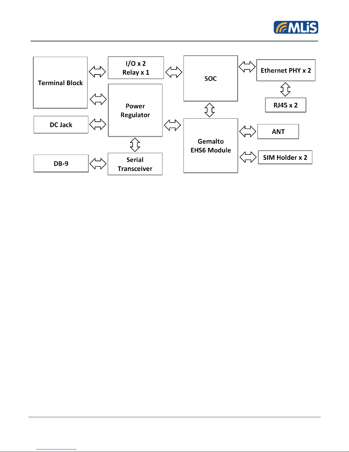
1.3 Functional Block Diagram
Figure 1: Functional Block Diagram for MLB-G4201
The MLB-G4201 consists of a fully certified (CE /NCC approved) GSM/GPRS engine, SIM card holder
and power regulator.
The wireless terminal is supplied with power via the DC jack. The remaining DB9 connector is used for
data communications.
The SMA female connector provides the air interface to an external 50 ohm antenna specified for the
correct frequency band.
MLB-G4201 Wireless Terminal User Manual 9 Rev 1.1
Page 10

1.4 Main Features and Services
S/N
Feature
Specifications
1
Frequency Bands
GSM/GPRS/EDGE: Quad band 850/900/1800/1900MHz
UMTS/HSPA+: Five band 800/850/900/1900/2100MHz
2
RF Output Power
Class 4 (+33dBm ±2dB) for EGSM850
Class 4 (+33dBm ±2dB) for EGSM900
Class 1 (+30dBm ±2dB) for GSM1800
Class 1 (+30dBm ±2dB) for GSM1900
Class E2 (+27dBm ± 3dB) for GSM 850 8-PSK
Class E2 (+27dBm ± 3dB) for GSM 900 8-PSK
Class E2 (+26dBm +3 /-4dB) for GSM 1800 8-PSK
Class E2 (+26dBm +3 /-4dB) for GSM 1900 8-PSK
Class 3 (+24dBm +1/-3dB) for UMTS 2100, WCDMA FDD BdI
Class 3 (+24dBm +1/-3dB) for UMTS 1900,WCDMA FDD BdII
Class 3 (+24dBm +1/-3dB) for UMTS 900, WCDMA FDD BdVIII
Class 3 (+24dBm +1/-3dB) for UMTS 850, WCDMA FDD BdV
Class 3 (+24dBm +1/-3dB) for UMTS 800, WCDMA FDD BdVI
3
GSM Class
Small MS
4
Power Supply
3.3V to 4.5V
5
Power Consumption
- DATA mode: GPRS 1TX, 4RX
GSM 850/EGSM 900
GSM 1800/1900
180mA
145mA
- DATA mode: GPRS 2TX, 3RX
GSM 850/EGSM 900
GSM 1800/1900
330mA
260mA
6
Operating Temperature
Normal operation: -40°C to +75°C
7
Data Transfer
GPRS:
• Multi-slot Class 12
• Full PBCCH Support
• Mobile Station Class B
• Coding Scheme 1 – 4
EGPRS:
• Multi-slot Class 12
• EDGE E2 power class for 8 PSK
The MLB-G4201 performs a set of telecom services (TS) according to GSM standard phase 2+, ETSI
and ITU-T. The services and functions of the MLB-G4201 are implemented by issuing customized
applications embedded on the device, or by AT commands issued internally, or over the RJ-45 to RS232 serial interface.
1.4.1 Wireless Terminal Features and Electrical Specifications
MLB-G4201 Wireless Terminal User Manual 10 Rev 1.1
Page 11
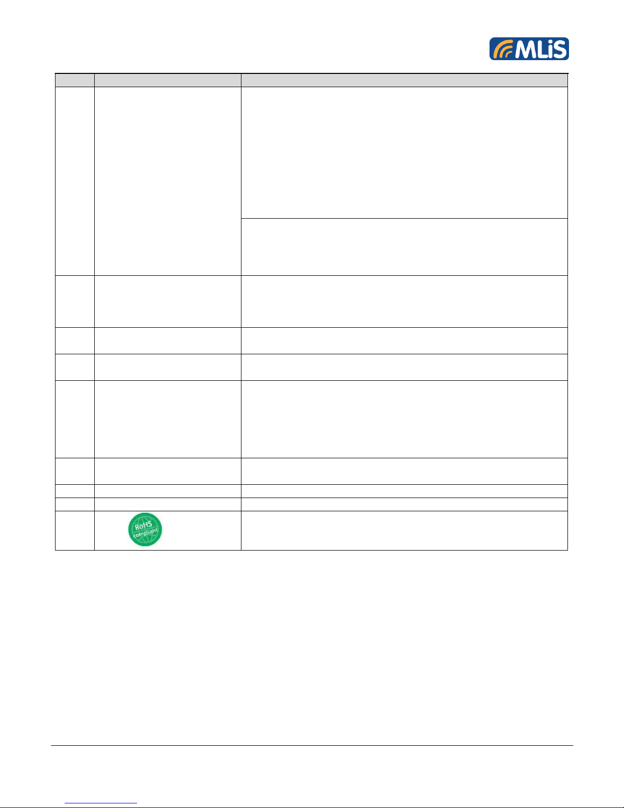
S/N
Feature
Specifications
• Downlink coding schemes – CS 1-4, MCS 1-9
• Uplink coding schemes – CS 1-4, MCS 1-9
• SRB loopback and test mode B
• 8-bit, 11-bit RACH
• PBCCH support
• 1 phase/2 phase access procedures
• Link adaptation and IR
• NACC, extended UL TBF
• Mobile Station Class B
CSD:
• V.110, RLP, non-transparent
• 9.6kbps
• USSD
8
SMS
Point-to-point MT and MO
Cell broadcast
Text and PDU mode
Storage: SIM card plus SMS locations in mobile equipment
9
AT Commands
Hayes 3GPP TS 27.007, TS 27.005, Gemalto M2M
AT commands for RIL compatibility
10
TCP/IP Stack
Access by AT Commands
Internet Services include TCP, UDP
11
Serial Interface
DB9 connector
8-wire Modem Interface with status and control lines,
unbalanced, asynchronous
Fixed bit rate: 1,200bps to 230, 400bps
Flow Control: Hardware RTS0/CTS0 and Software XON/OFF
Multiplex ability according to GSM 07.10 Multiplexer Protocol
12
SIM Interface
2*SIM Card Slot
Supports SIM Cards: +3V and +1.8V
13
Antenna
50 ohms via External SMA Connector
14
Software Reset
Orderly shutdown and Reset by AT Command (AT^SMSO)
15
RoHs
All hardware components are fully compliant with the EU RoHs
directive 2002/95/EC
Exception: MLB55IN
Table 2: Features and Specifications
1.5 Precautions
The MLB-G4201 wireless terminal is designed for indoor use only. For outdoor use it has to be
integrated into a weatherproof enclosure. Do not exceed the environmental and electrical limits as
specified in the user manual.
MLB-G4201 Wireless Terminal User Manual 11 Rev 1.1
Page 12

2 MECHANICAL DESCRIPTION
S/N
Parameter
Value
1
Height (H)
48mm
2
Length (L)
121mm
3
Width (W)
88.0mm
4
Weight
420g
5
Chassis Material
Metal
2.1 Overview
The pictures below show the mechanical design of the wireless terminal along with the positions of the
different connectors.
2.2 Dimensions
Figure 2: Chassis Dimension for MLB-G4201
Table 1: Chassis Dimensions and Mechanical Description for MLB-G4201
MLB-G4201 Wireless Terminal User Manual 12 Rev 1.1
Page 13
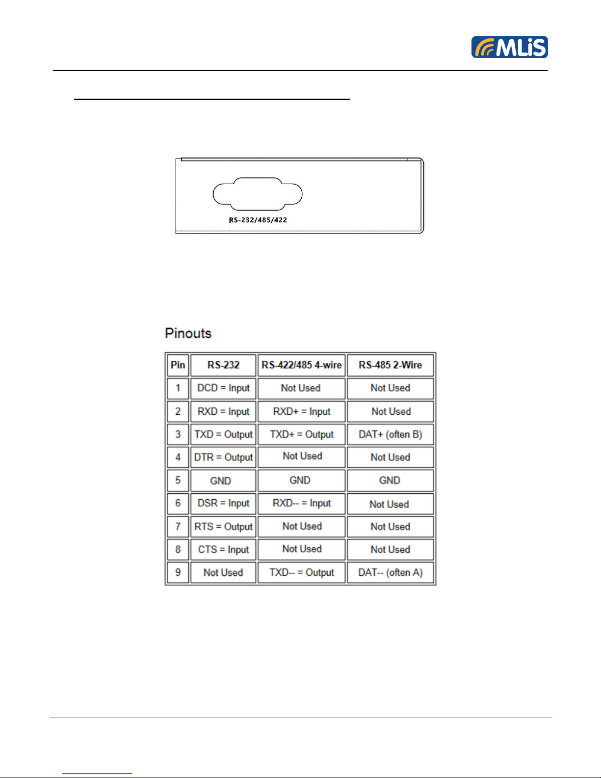
3 ELECTRICAL INTERFACE DESCRIPTIONS
3.1 Right side view (DB9 connector)
Figure 3:RS232/RS422/RS485 for MLB-G4201
The table below defines the RS-232/422/485 pin configuration on the wireless terminal.
Table 2: DB9 Pins Definition for MLB-G4201
MLB-G4201 Wireless Terminal User Manual 13 Rev 1.1
Page 14
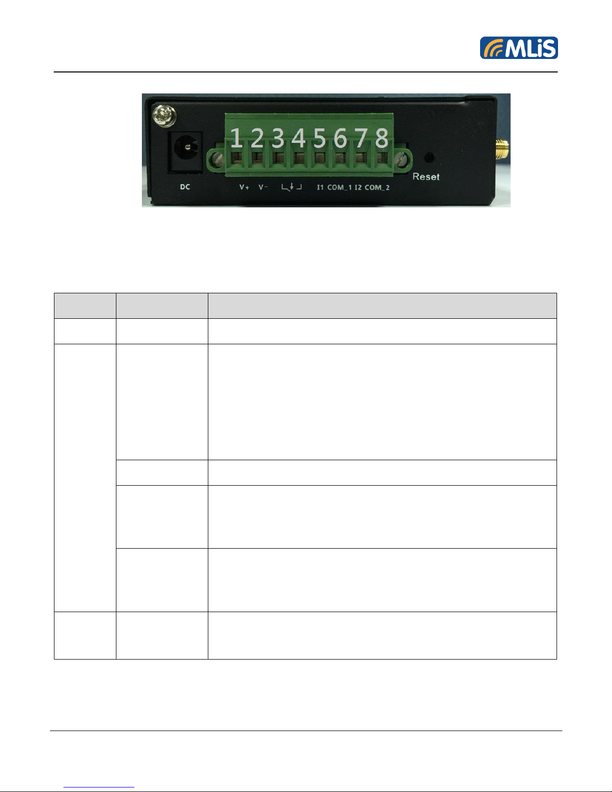
3.2 Left side view (DC Jack & Industry Connector)
Name
Description
Function
DC
DC
Input Power:+9V~+48V
Terminal
Block
PWR(V+, V-)
• Input Power:+9V~+48V
• Pin #1 is V+
• Pin #2 is V-
• When use DC for input, the output power of TB is same as input
power
Do Not use DC & PWR to be the input power at the same time,
it may cause damage to the equipment.
Relay
External Relay:max+40V
DI1(I1, COM_1)
Pin #5 is +
Pin #6 is -
• I1: external signal +12V~+48V
• COM_1:common grand
• Pin #5 is +
• Pin #6 is -
DI2(I2, COM_2)
Pin #7 is +
Pin #8 is -
• I2:external signal, +12V~+48V
• COM_2: comman grand
• Pin #7 is +
• Pin #8 is -
Reset
Reset
• 1-click to reboot MLB-G4201.
• Double click to set MLB-G4201 into configuration mode.
• Long press over 5 seconds to reset MLB-G4201 to default.
Figure 4: DC and Industry Connector for MLB-G4201
The interfaces and indicators for MLB-G4201 are as follows:
Table 3: Interfaces and Indicators Description of MLB-G4201
MLB-G4201 Wireless Terminal User Manual 14 Rev 1.1
Page 15
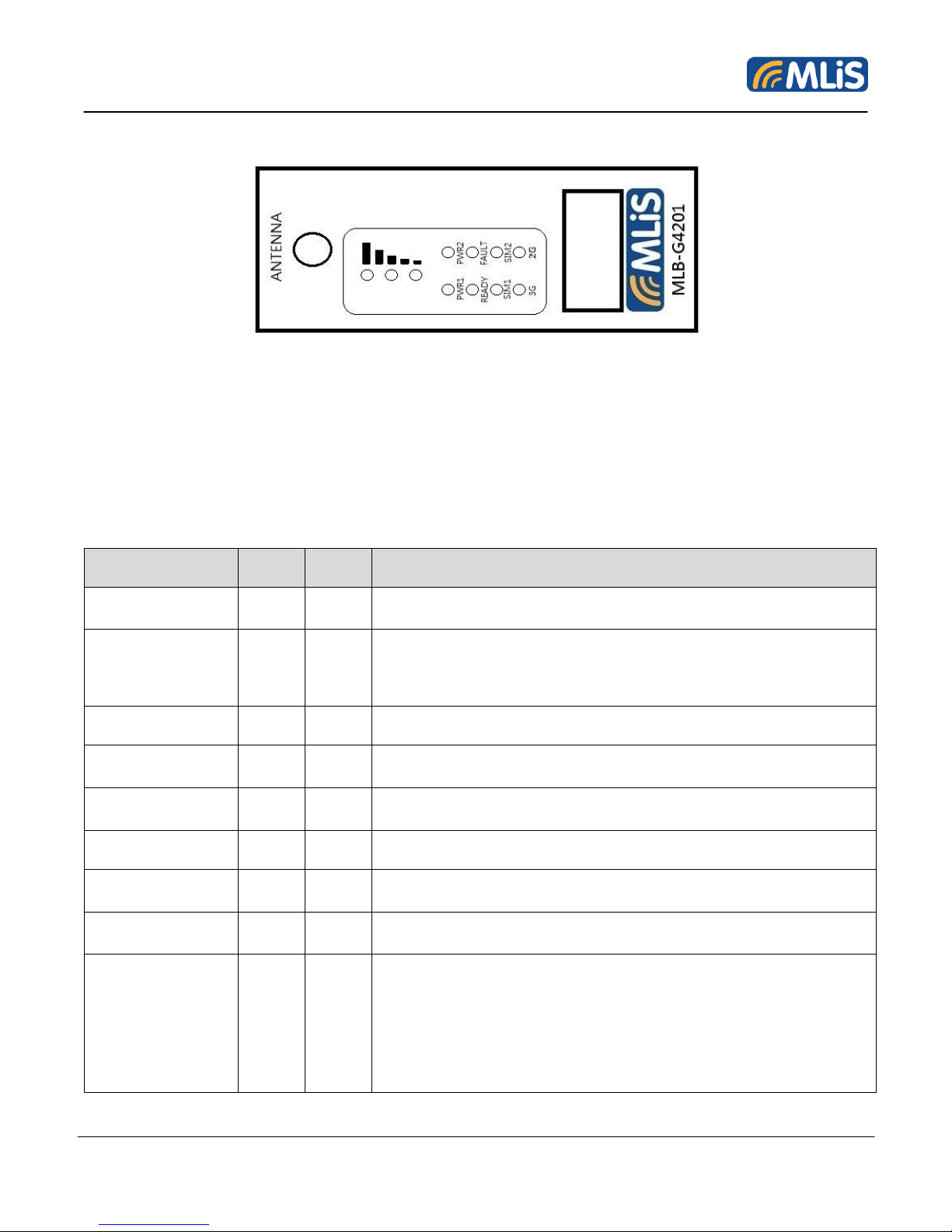
3.3 Frond view (Antenna & LED)
LED
Color
State
Description
PWR1 (DC)
Green
On
Power is being supplied from power input 1.
PWR2
(Terminal Block)
Green
On
Power is being supplied from power input 2.
READY
Green
On
System startup is complete and the system is operating.
Blink
Device has been located.
Off
Power is off, or the system is booting up.
FAULT
Red
On
System configuration error or a relay event has occurred.
Blink
IP address conflict.
Off
Power is off, or there is no error condition.
SINGNAL
(3LEDs)
Green
On
Number of LEDs to indicate cellular signal level when registered
to a base station.
Signal LED 1: 0 < RSSI ≤ 12
Signal LED 2: 12 < RSSI ≤ 21
Figure 5: Antenna Connector for MLB-G4201
For optimum RF performance, the MLiS wireless terminal has to be connected to an external RF
antenna matched to 50ohms. Please use a SMA Male connection for the wireless terminal.
The functions of LED are indicated on the table below.
MLB-G4201 Wireless Terminal User Manual 15 Rev 1.1
Page 16

Signal LED 3: 22 < RSSI ≤ 31
SIM1
Amber
On/Off
SIM 1 is active or inactive.
Blink
SIM 1 is not inserted or PIN code is incorrect.
SIM2
Amber
On/Off
SIM 2 is active or inactive.
Blink
SIM 2 is not inserted or PIN code is incorrect.
3G
Amber
On
Registered to a base station with cellular connection in UMTS or
HSPA mode.
2G
Amber
On
Registered to a base station with cellular connection in LTE
mode.
Table 4: LED Functions of MLB-G4201
MLB-G4201 Wireless Terminal User Manual 16 Rev 1.1
Page 17

3.4 SIM card holder
In the bottom, the MLB-G4201 wireless terminal is provided with a SIM card reader designed for 1.8V
and 3V SIM cards. It is the flip-up type which can be locked. It can be accessed through removing the
battery cover as shown below.
Figure 6: SIM Card Holder for MLB-G4201
Be sure to power off the modem when user replaces the SIM card. Otherwise it may cause
damage to the equipment.
The MLB-G4201 fully operates when inserting a SIM card. Some MLB-G4201 functionality may be lost
if user try to operate the wireless terminal without a SIM card.
MLB-G4201 Wireless Terminal User Manual 17 Rev 1.1
Page 18
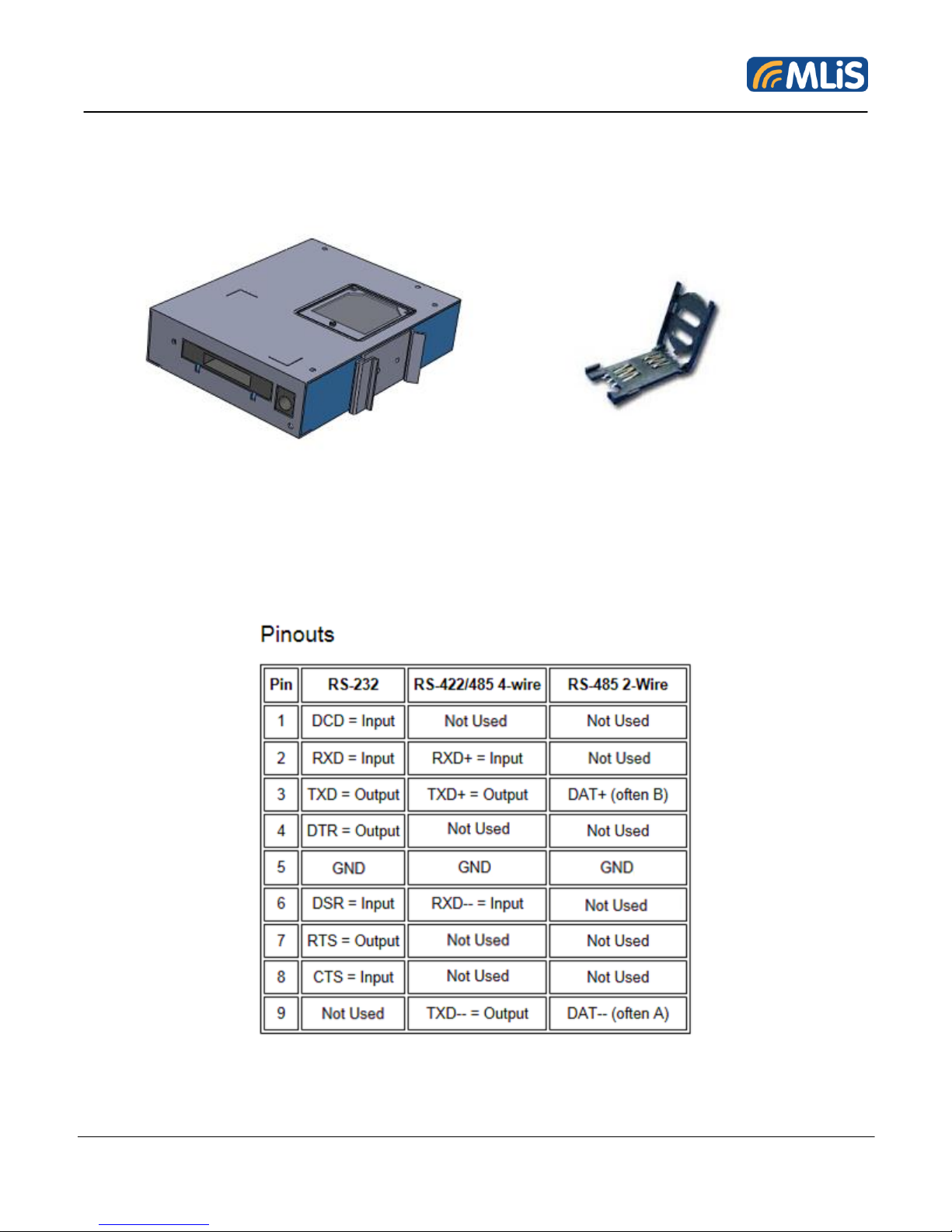
3.5 Getting Started
HW installation
Step 1:Please insert SIM card into SIM card holder as follows.
Be sure to power off the modem when user replaces the SIM card. Otherwise it may cause
damage to the equipment.
Step 2:Please connect serial port to device as following Pinouts
MLB-G4201 Wireless Terminal User Manual 18 Rev 1.1
Page 19
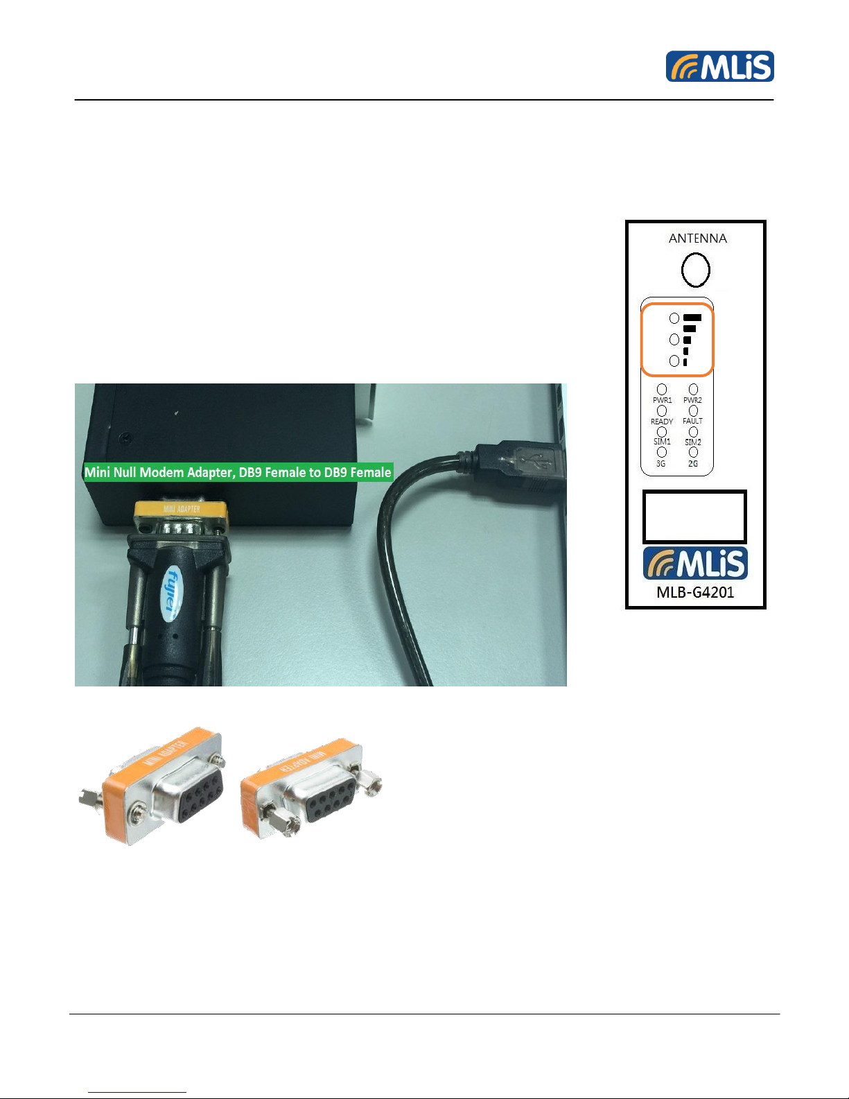
Step 3: Please connect power supplier with 5~32VDC, then boot up. The LED will light up when MLBG4201 ready.
Step 4:After plug-in power adapter. The wireless terminal is usually fully operational within 30
seconds, after powering it up. Depending on the signal strength of the network in the area, logging into
a network may take longer and is outside the control of the wireless terminal.
The device is ready after LED of signal is lighted. Then user can operate it.
Step 5: When user use the MCCU (MLiS Cellular Configuration Utility) to
configure MLB-G4201, please refer the connection as below:
MLB-G4201 Wireless Terminal User Manual 19 Rev 1.1
Page 20

4 SW Installation
Preliminary work: Power on MLB-G4201 and use web console cable to configure MLB-G4201.
4.1 Web Console
Set PC & MLB-G4201 into same subnetwork. The Default IP of MLB-G4201 is 10.0.10.1. Please set up
your PC with the same network segment, such as 10.0.10.2. So you can use browser to access the
web console of MLB-G4201. Please enter ID and password as below:
Username: admin
Password: 1234
MLB-G4201 Wireless Terminal User Manual 20 Rev 1.1
Page 21

4.2 Overview
Item
Description
Model name
Display the model name
Device name
Display the device name
Serial No
Display the serial number
System up time
Display system run times
Firmware version
Display the Firmware version
Firmware build time
Display the Firmware build time
This page will display the system information of MLB-G4201.
4.2.1 System Info
MLB-G4201 Wireless Terminal User Manual 21 Rev 1.1
Page 22
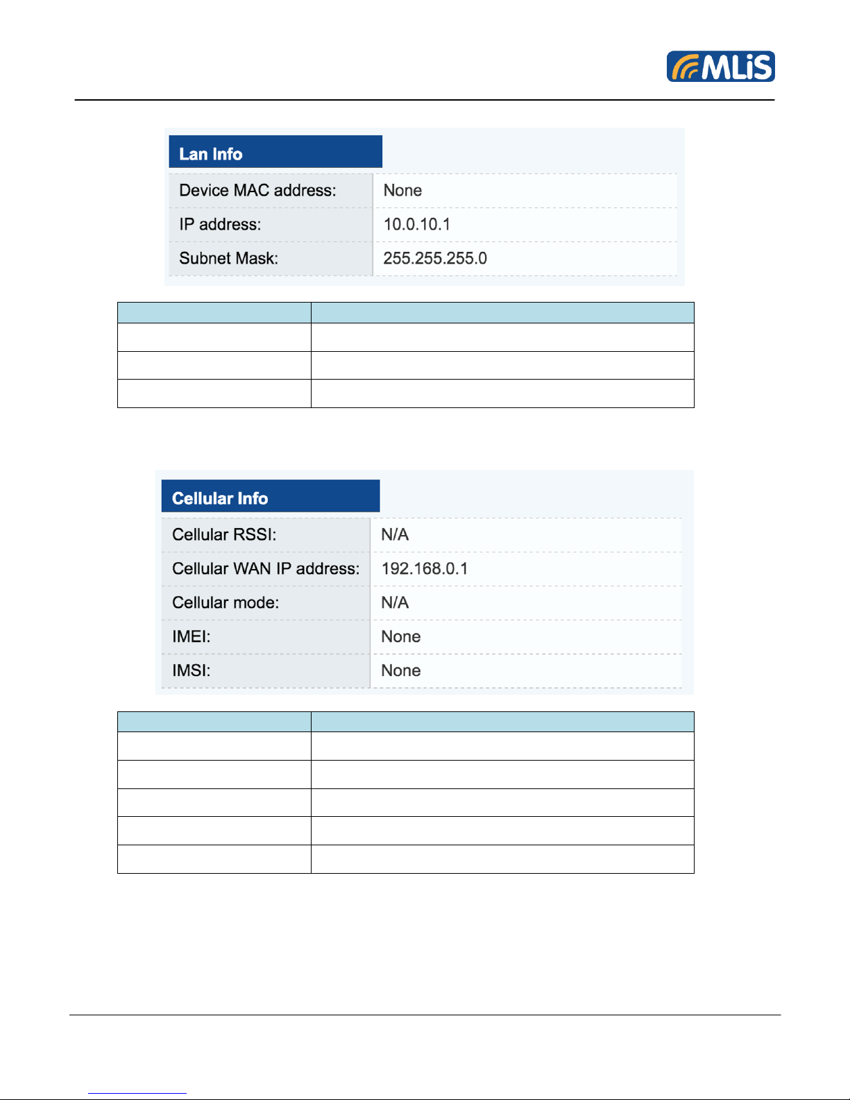
4.2.2 LAN Info
Item
Description
Device MAC address
Display physical address
IP address
Display the IP address
Subnet Mask
Display the subnet mask
Item
Description
Cellular RSSI
Signal
Cellular WAN IP address
Display the WAN IP address
Cellular mode
Display the cellular mode
IMEI
IMSI
4.2.3 Cellular Info
MLB-G4201 Wireless Terminal User Manual 22 Rev 1.1
Page 23
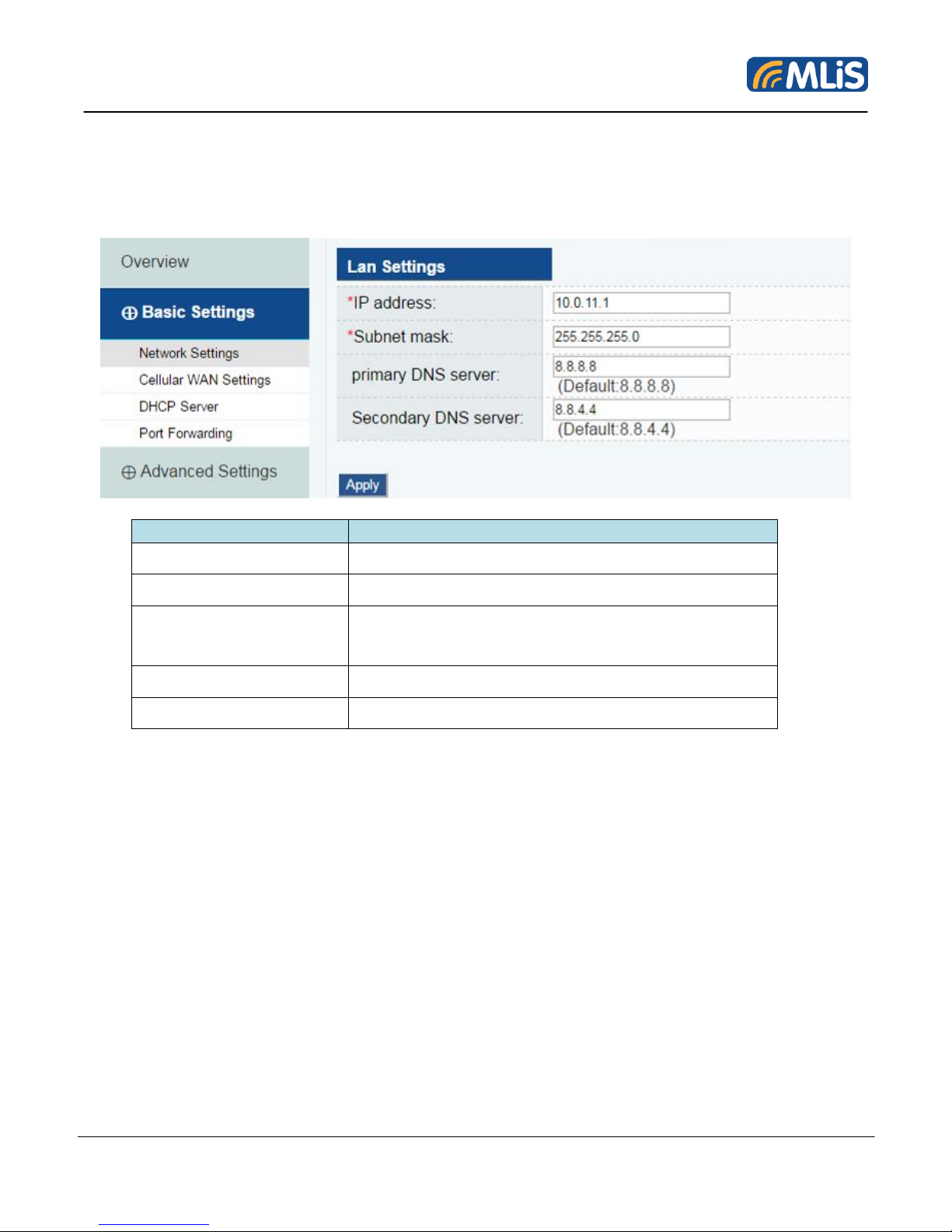
4.3 Basic Settings
Item
Description
IP Address
Enter the unique IP address for the MLB-G4201
Subnet mask
Enter the subnet mask to specify the type of network.
Primary DNS server
Enter the IP address of the primary DNS server.
After you specify a DNS server, you can access a web
site by entering its URL instead of the IP address.
Secondary DNS server
Enter the IP address of the secondary DNS server.
Apply
Click to save all settings.
The Basic Settings group includes the most commonly used settings required by administrators to
maintain and control the MLB-G4201.
4.3.1 Network Settings
MLB-G4201 Wireless Terminal User Manual 23 Rev 1.1
Page 24
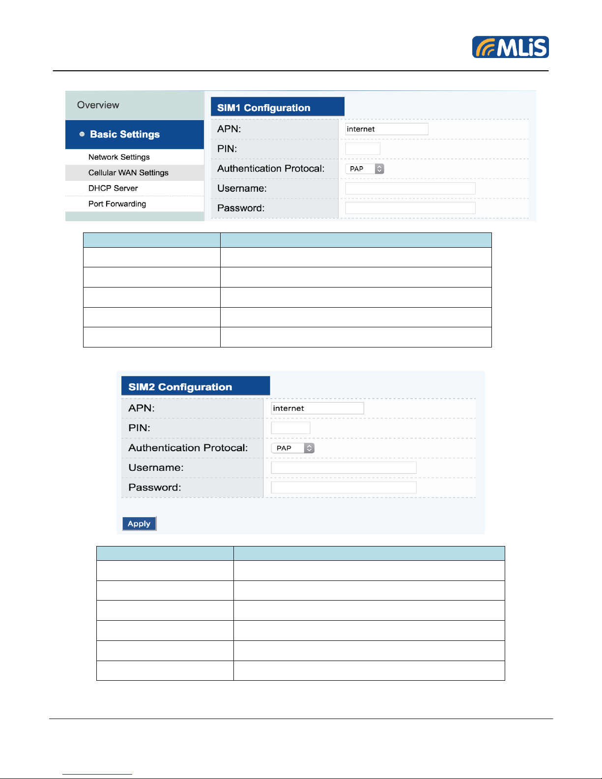
4.3.2 Cellular WAN Settings
Item
Description
APN
Access Point Name
PIN
Personal Identification Number
Authentication Protocol
Username
Password
Item
Description
APN
Access point name
PIN
Personal identification number
Authentication Protocol
Username
Password
Apply
Click to save all settings.
MLB-G4201 Wireless Terminal User Manual 24 Rev 1.1
Page 25
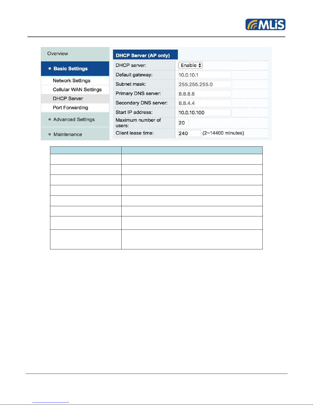
4.3.3 DHCP Server
Item
Description
DHCP server
Select “Enable” or “Disable” by drop-down list
Default gateway
Set default gateway
Subnet mask
Set subnet mask
Primary DNS server
Set IP address of the primary DNS server.
Second DNS server
Set IP address of the secondary DNS server.
Start IP address
Enter the starting IP address in the IP address pool.
Maximum number of
users
Enter the number (1~999) of IP address to assign to
DHCP clients.
Client lease time
Enter the lease time (2~14400 minutes) for an
assigned IP address.
The IP address expired after the lease time.
MLB-G4201 Wireless Terminal User Manual 25 Rev 1.1
Page 26
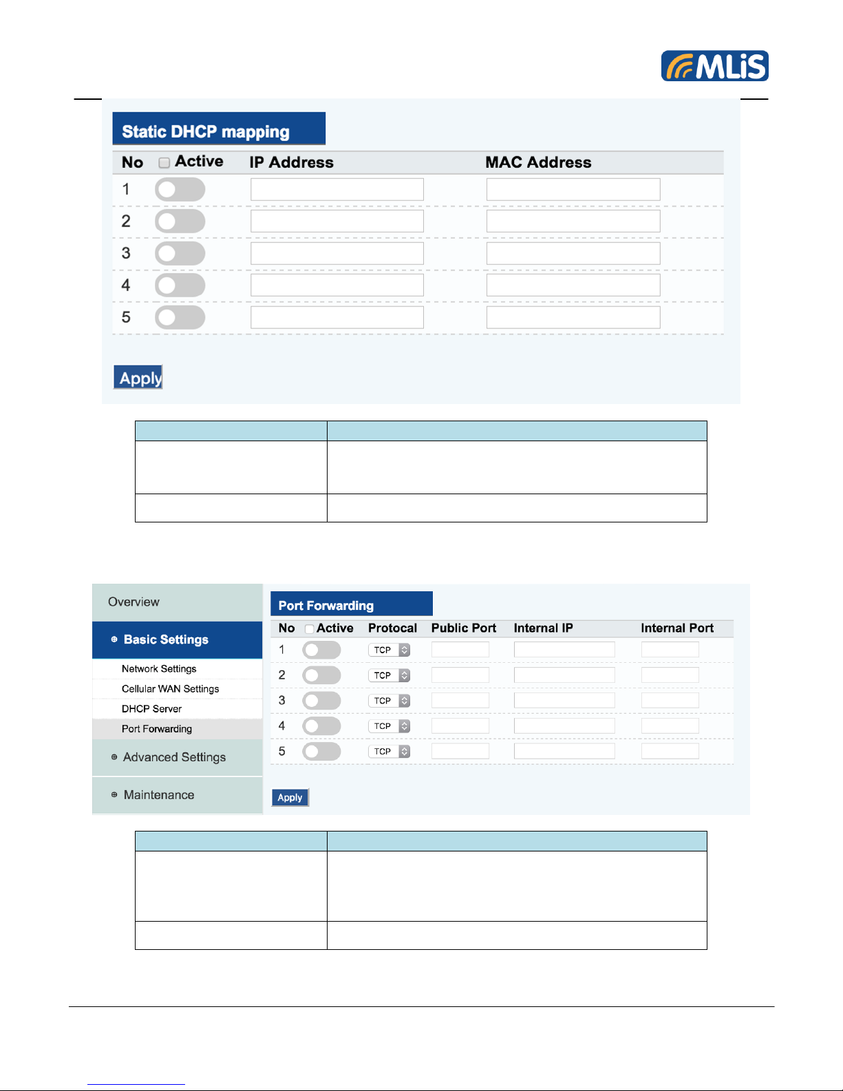
Item
Description
Static DHCP mapping
1. Input MAC address and assign IP address.
2. Enable the mapping setting.
3. Click Apply to save settings.
Apply
Click to save all settings.
Item
Description
Static DHCP mapping
1. Select Protocol and input Public Port, Internal IP,
and Internal Port.
2. Enable the mapping setting.
3. Click Apply to save settings.
Apply
Click to save all settings.
4.3.4 Port Forwarding
MLB-G4201 Wireless Terminal User Manual 26 Rev 1.1
Page 27
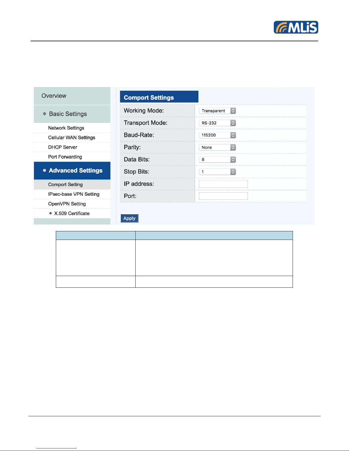
4.4 Advanced Settings
Item
Description
COM Port setting
1. Select Working Mode, Transport Mode, BaudRate, Parity, Data Bits, Stop Bits by drop-down
list.
2. Input IP & Port.
3. Click Apply to save settings.
Apply
Click to save all settings.
Several advanced functions are available to increase the functionality of your MLB-G4201 and wireless
network system.
4.4.1 Com Port Setting
MLB-G4201 Wireless Terminal User Manual 27 Rev 1.1
Page 28
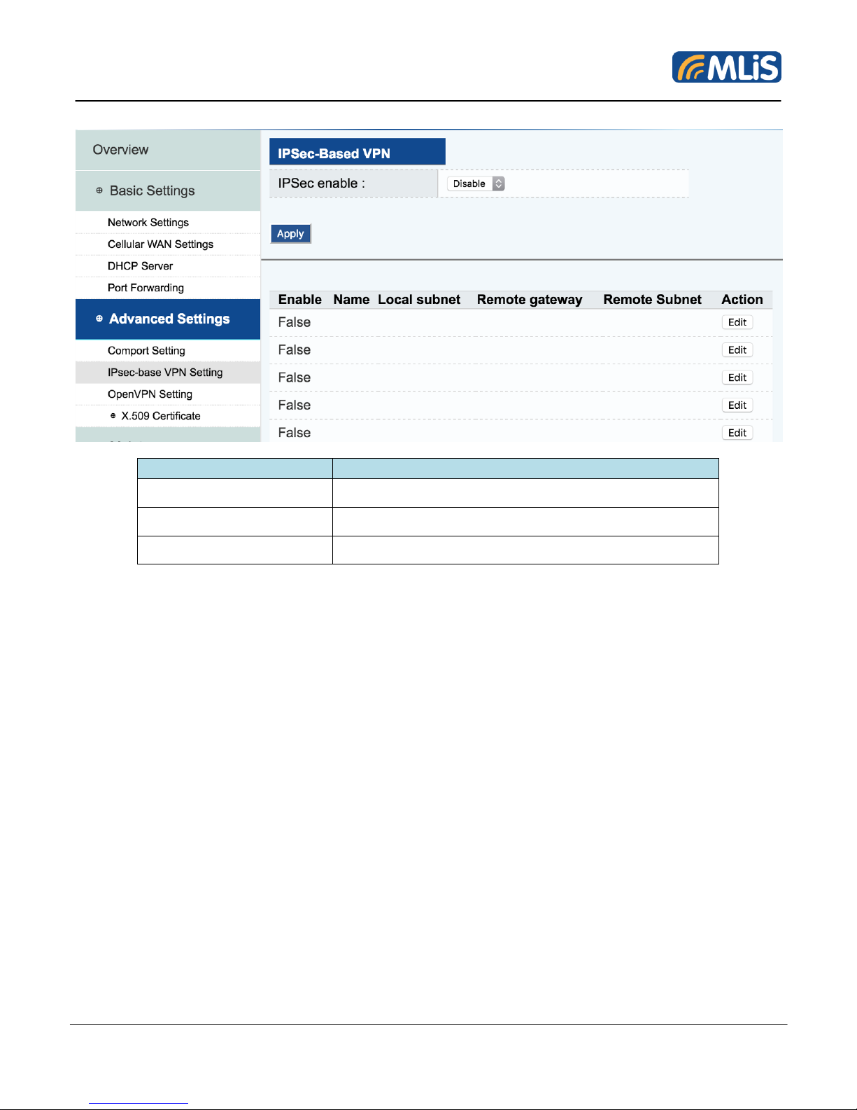
4.4.2 IPsec-base VPN Setting
Item
Description
IPSec Enable
Select “Enable” to enable the IPsec function.
Edit
Click “Edit” to create IPsec settings.
Apply
Click to save all settings.
MLB-G4201 Wireless Terminal User Manual 28 Rev 1.1
Page 29
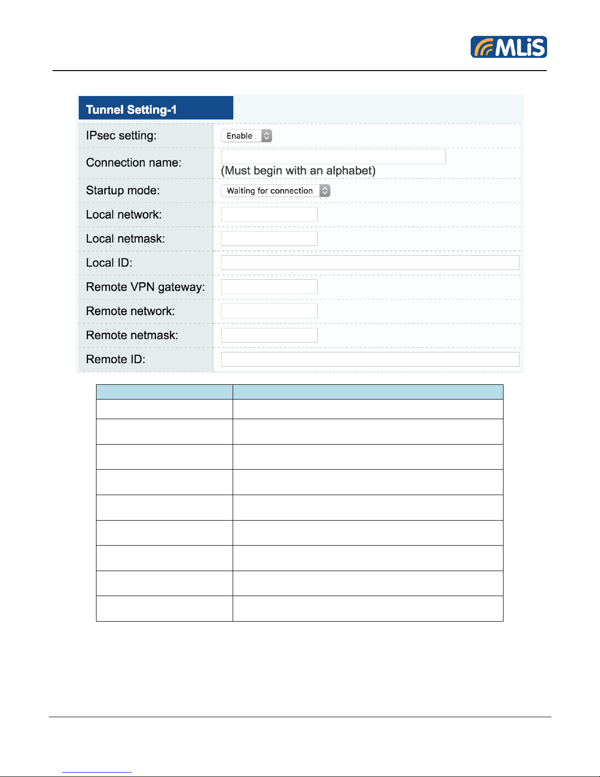
IPsec settings
Item
Description
Connection name
Enter a descriptive name for the VPN tunnel.
Startup mode
Select Start in Initial to set the MLB-G4201 to initiate a
connection with the remote VPN gateway.
Local network
Enter the remote VPN server subnet IP of the local
network.
Local netmask
Enter the remote VPN server subnet netmask of the
local network.
Local ID
Enter an ID to identify and authenticate the local VPN
gateway.
Remote VPN gateway
Enter the WAN IP address of the remote VPN
gateway.
Remote network
Enter the remote VPN server subnet IP of the remote
network.
Remote netmask
Enter the remote VPN server subnet netmask of the
remote network
Remote ID
Enter an ID to identify and authenticate the remote
VPN endpoint.
MLB-G4201 Wireless Terminal User Manual 29 Rev 1.1
Page 30
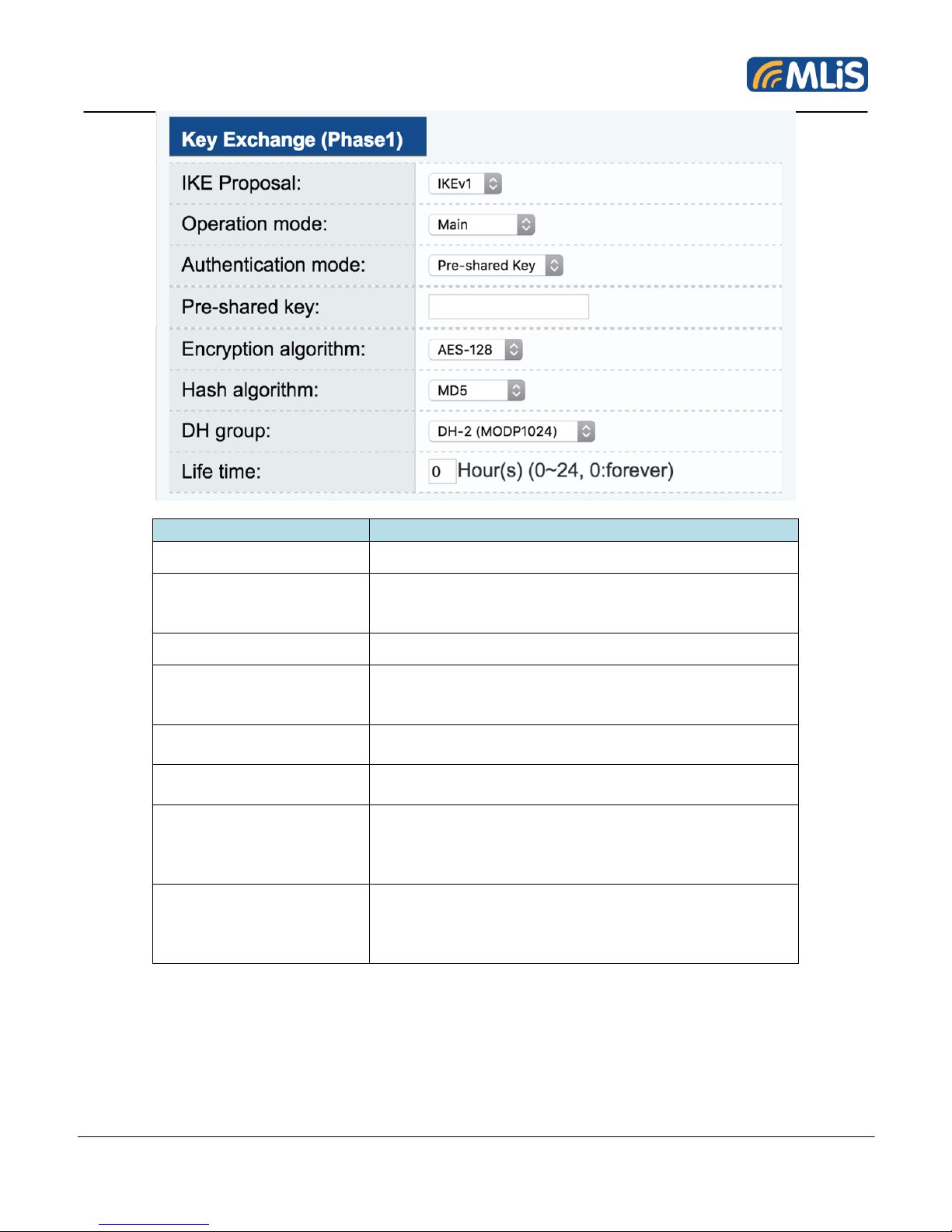
Item
Description
IKE Proposal
Select IKEv1 or IKEv2
Operation mode
Select main mode or aggressive mode to configure
the standard negotiation parameters for IKE Phase 1
of the VPN Tunnel.
Authentication mode
Pre-shared key
Select Pre-shared key authentication mode to for
phase 1 key exchange. The configuration fields vary
depending on the authentication mode you select.
Encryption algorithm
Select the DES, 3DES or AES128 algorithm for the VPN
ISAKMP phase 1 encryption mode.
Hash algorithm
Select the MD5 or SHA-1 VPN key exchange phase 1
hash mode.
DH group
Select the DH-2 (1024) or DH-5 (1536) VPN key
exchange phase 1 Diffie-Hellman group. As the DiffieHellman Group number increases, the higher the level
of encryption implemented for PFS.
Life time:
Enter the number of minutes for the VPN IKE SA
phase 1 Lifetime. This is the period of time to pass
before establishing a new IPSec security association
(SA) with the remote endpoint.
MLB-G4201 Wireless Terminal User Manual 30 Rev 1.1
Page 31
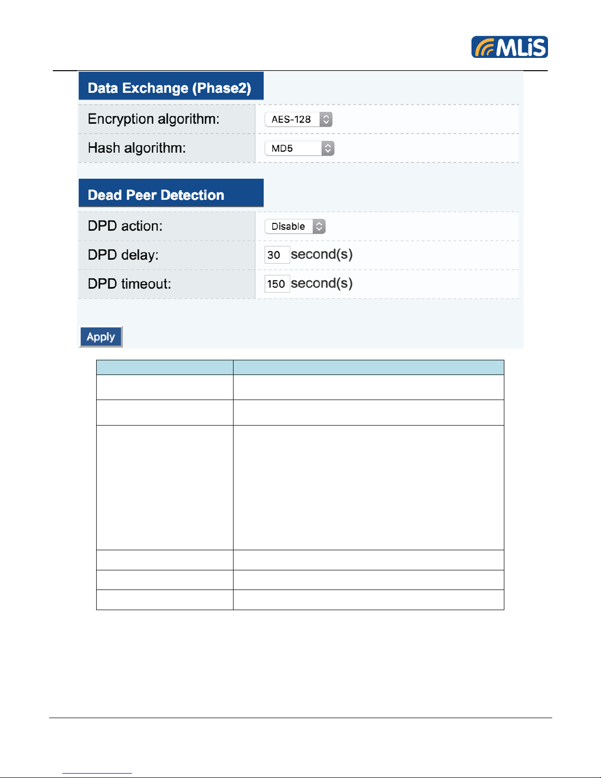
Item
Description
Encryption algorithm:
Select the DES, 3DES or AES128 algorithm for the
VPN ISAKMP phase 2 encryption mode.
Hash algorithm:
Select the MD5 or SHA-1 VPN key exchange phase 2
hash mode.
Dead Peer Detection:
When you enable the Dead Peer Detection (DPD)
feature, the OnCell G3470A-LTE performs one of the
following actions when connection to a remote IPSec
tunnel is down:
• Hold: Keep the VPN tunnel
• Clear: Clear the VPN tunnel
• Restart: Re-establish the VPN tunnel on Start in
Initial mode.
• Restart by Peer: Re-establish the VPN tunnel on
Wait for connecting mode
DPD delay
The period of dead peer detection messages.
DPD timeout
Timeout to check if the connection is alive or not.
Apply
Click to save all settings.
MLB-G4201 Wireless Terminal User Manual 31 Rev 1.1
Page 32

4.5 Maintenance
Item
Description
Destination
Inputting a node’s IP address in the Destination field,
you can use the ping command to make sure it exists
and whether or not the access path is available.
Ping
Click to ping.
Item
Description
Command
Input AT command in the command field.
Send
Click to send.
Maintenance functions provide the user to manage the MLB-G4201 and wired/wireless networks.
4.5.1 Ping
4.5.2 AT Command
MLB-G4201 Wireless Terminal User Manual 32 Rev 1.1
Page 33
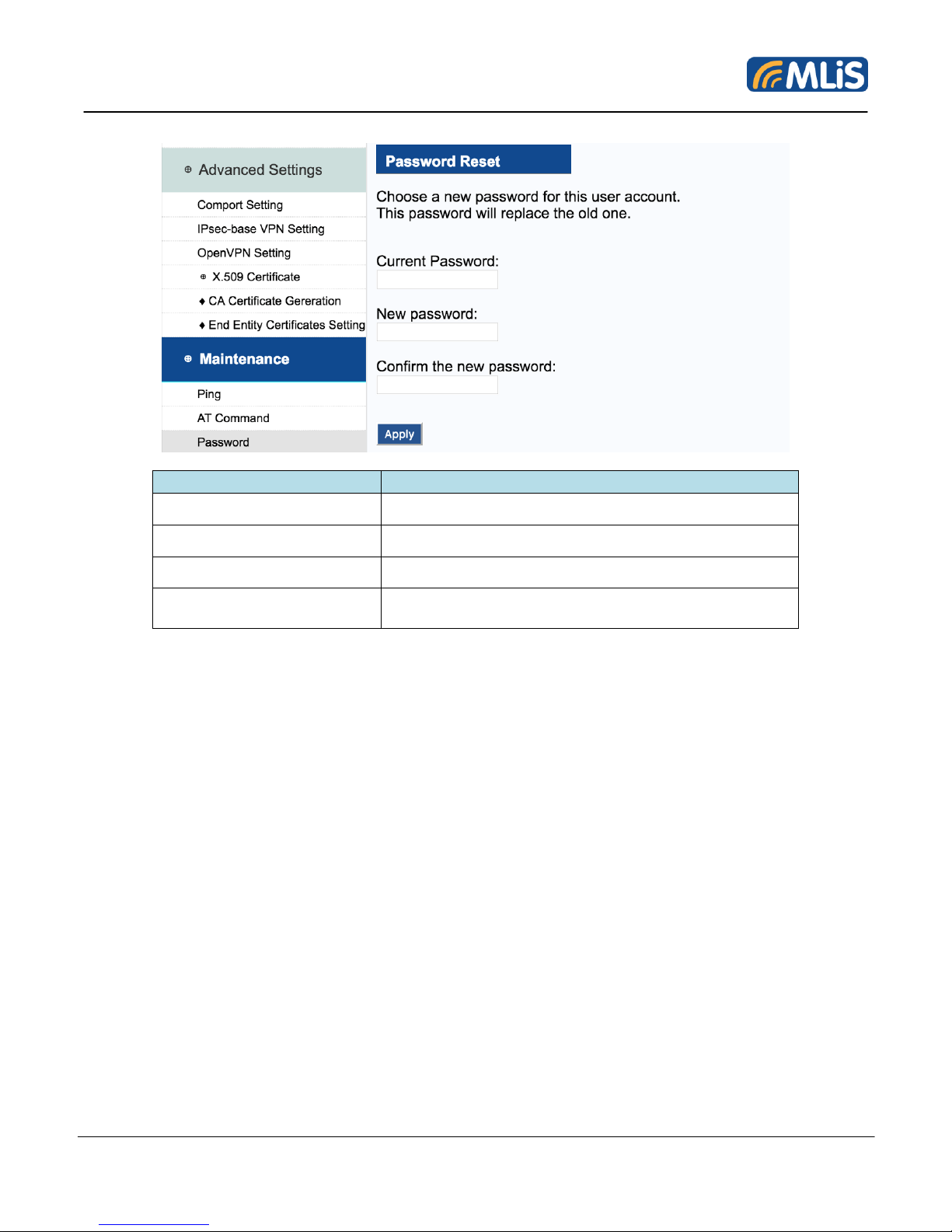
4.5.3 Password
Item
Description
Current Password
Input current password.
New password
Input new password.
Confirm the new password
Input new password again.
Apply
Click Apply to change password.
Need to click save to complete the process.
MLB-G4201 Wireless Terminal User Manual 33 Rev 1.1
Page 34
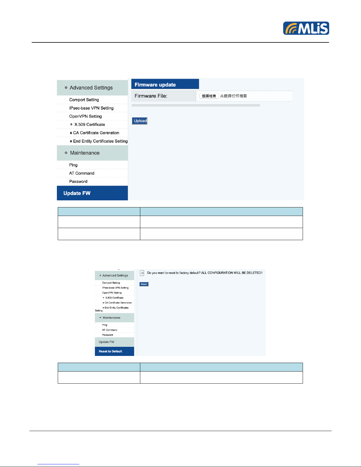
4.6 Update FW
Item
Description
Firmware File
Click to load .fw file
Upload
Click to upgrade the FW
Item
Description
Reset
Click to reset MLB-G4201 to default.
The MLB-G4201 can be enhanced with more value-added functions by installing firmware upgrades.
Please contact MLiS website to get latest firmware.
4.7 Reset to Default
MLB-G4201 Wireless Terminal User Manual 34 Rev 1.1
Page 35

4.8 Status
Item
Description
DI1
Click GET to gather the status of DI1.
DI2
Click GET to gather the status of DI2.
Relay
Trigger the Relay to enable/disable relay.
4.8.1 IO/Relay Status
4.8.2 IPSec Log/OpenVPN Log/Syslog
MLB-G4201 Wireless Terminal User Manual 35 Rev 1.1
Page 36
Syslog: 查看開機及操作設定相關訊息記錄
Item
Description
IPSec Log
Record the IPSec log.
OpenVPN Log
Record the OpenVPN log.
Sysloog
Record the syslog.
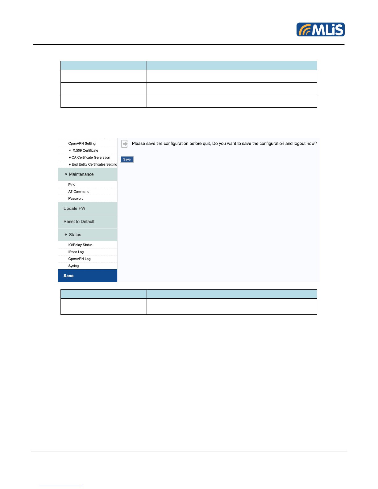
Item
Description
Save
Click Save to save all setting you set. Then MLBG4201 will reboot.
4.9 Save
MLB-G4201 Wireless Terminal User Manual 36 Rev 1.1
Page 37

5 OPERATING NOTE
5.1 Power on the Modem
After plugin the power adapter, the modem is usually fully operational within 4 seconds, after
powering it up. Depending on the signal strength of the network in the area, logging into a
network may take longer and is outside the control of the modem.
5.2 Reset to default
Press reset button, it will be reset to default. All of temporary data buffer will be clear.
5.3 External input x2
External signal input source, positive signal are DI1 and DI2, negative signal are COM_1 are COM_2.
Power input range is +12V~+48V, it will be determined as positive. It can be used for alert.
5.4 External Relay x1
Non positive and negative signal relay output, maximum power input voltage range is +48V. It can be
used for beeper.
5.5 DB9 Connector
The RS-232/422/485 connector is DB9 male type, please refer to table 4.
5.6 Install SIM card
Please turn to back view, screw open the cover, then user will see SIM card holder. Please use SIM
card faces to PCB board and put it into holder, please screw the cover back.
MLB-G4201 Wireless Terminal User Manual 37 Rev 1.1
Page 38
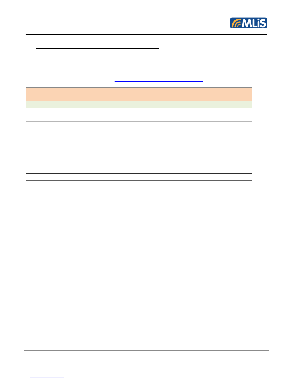
6 MLiS Cellular Control Protocol (MCCP)
MLB-G4201 MCCP (SMS / Host via internet / Host via RS232)
Initial Step
Protocol
Action
MLB-CONFIGSTAGE1
Waiting for : IN STAGE1
HEX:
4D 4C 42 2D 43 4F 4E 46 49 47 53 54 41 47 45 31 00 00 00 00 00 00 00 00 00 00 00 00 00
00 00 00 00 00 00 00 00 00 00 00 00 00 00 00 00 00 00 00 00 9D
MLB-CONFIGSTAGE2
Waiting for : IN STAGE2
HEX:
4D 4C 42 2D 43 4F 4E 46 49 47 53 54 41 47 45 32 00 00 00 00 00 00 00 00 00 00 00
00 00 00 00 00 00 00 00 00 00 00 00 00 00 00 00 00 00 00 00 00 00 9C
MLB-CONFIGSTAGE3
Waiting for : MLB-G4201 into configuration mode
HEX:
4D 4C 42 2D 43 4F 4E 46 49 47 53 54 41 47 45 33 00 00 00 00 00 00 00 00 00 00 00
00 00 00 00 00 00 00 00 00 00 00 00 00 00 00 00 00 00 00 00 00 00 9B
Notice :
The wireless terminal will exit the configuration mode automatically when wireless
terminal does not get any MCCP exceed 12 seconds in working mode.
MLiS user can remotely control MLB-G4201 through MLiS Cellular Control Protocol. MLiS Cellular
Control Protocol is open to MLiS user.
The MCCP should be converted to hexadecimal then count with checksum. If any question about
MCCP, please feel free to contact us. [email protected]
MLB-G4201 Wireless Terminal User Manual 38 Rev 1.1
Page 39
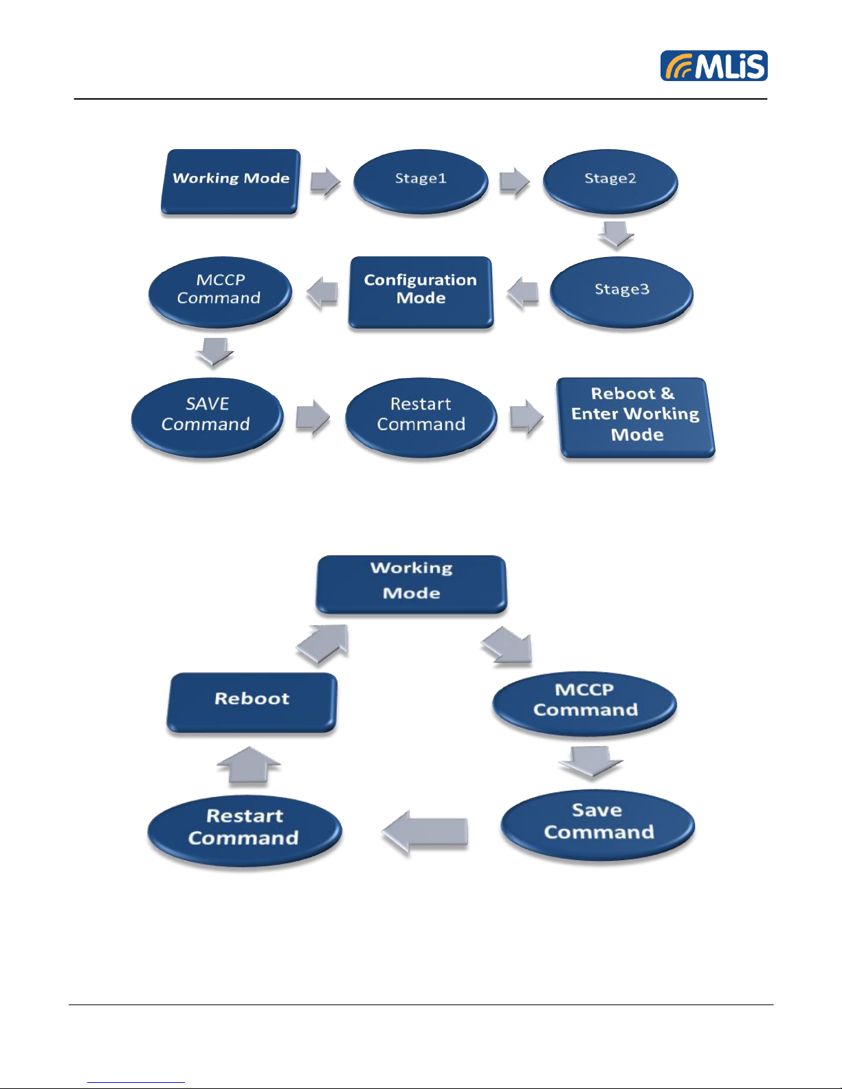
MCCP Setting Process via Internet/RS-232
MCCP Setting Process via SMS (using admin phone number)
MLB-G4201 Wireless Terminal User Manual 39 Rev 1.1
Page 40

Connection Profile
Write
Command Header
MLB-CONNECTIONPROFILE
Connection Type
1. Transparent Client Packing Mode
2. Transparent Client Fast Mode
3. Transparent Server Packing Mode
4. Transparent Server Fast Mode
5. Socket UDP Client Mode
6. Socket TCP Client Mode
7. Socket TCP Server Mode
Connection Index
0 ~ 4
IP Address
ex: 192.168.1.1: 36000
Maximum 37 chars
Enabled bit
0. Disabled
1. Enabled
End Tag
Z
Example:
MLB-CONNECTIONPROFILE: 6, 2, 192.168.100.99: 27000, 1, Z
set 192.168.100.99 port 27000 to profile 2 for TCP Client Mode (enabled).
Read
Command Header
MLB+CONNECTIONPROFILE:
Connection Type
1. Transparent Client Packing Mode
2. Transparent Client Fast Mode
3. Transparent Server Packing Mode
4. Transparent Server Fast Mode
5. Socket UDP Client Mode
6. Socket TCP Client Mode
7. Socket TCP Server Mode
Connection Index
0 ~ 4
End Tag
Z
Response Format
Response +: {IP}: {Port}, {Disable (0)/ Enable (1)
bit}
Example:
Send --> MLB+CONNECTIONPROFILE: 6, 2, Z
Response +: 192.168.99.22:54321,1
(Socket TCP Client Mode at Index 2 IP 192.168.99.22:54321 has been
enabled)
MLB-G4201 Wireless Terminal User Manual 40 Rev 1.1
Page 41
UART Setting
Write
Command Header
MLB-UARTSETTING
UART Type
1. RS232
2. RS485
3. RS422
Baud rate
0. 230400
1. 115200
2. 57600
3. 38400
4. 19200
5. 9600
6. 4800
7. 2400
8. 1200
9. 300
10. 110
Parity Bit
1. None
2. ODD
3. EVEN
Stop Bit
1. 1-bit
2. 2-bit
HW Flow Control
0. Disable
1. Enable
DTR Level
0. High Level
1. Low Level
RTS Level
1. High Level
2. Low Level
End Tag
Z
Example:
MLB-CONNECTIONPROFILE: 6, 2, 192.168.100.99: 27000, 1, Z
set 192.168.100.99 port 27000 to profile 2 for TCP Client Mode (enabled)
Read
Command Header
MLB+UARTSETTING
UART Type
1. RS232
2. RS485
3. RS422
Baud rate
0. 230400
1. 115200
2. 57600
3. 38400
4. 19200
5. 9600
6. 4800
7. 2400
8. 1200
9. 300
MLB-G4201 Wireless Terminal User Manual 41 Rev 1.1
Page 42
10. 110
Parity Bit
1. None
2. ODD
3. EVEN
Stop Bit
1. 1-bit
2. 2-bit
HW Flow Control
0. Disable
1. Enable
DTR Level
1. High Level
2. Low Level
RTS Level
1. High Level
2. Low Level
End Tag
Z
Response format
Response +: {UART Mode }, {Baud rate}, {Parity
Bit}, {Stop Bit}, {HW Flow Control (Disable /
Enable)}, {DTR (H/L)}, {RTS (H/L)}
Example:
Send --> MLB+UARTSETTING: Z
Response +:1, 1, 2, 2, 0, 0, 1
(UART Mode is RS232 at 115200 / ODD / 2Bits / H/W flow control disabled
/ DTR at Low / RTS at High)
MLB-G4201 Wireless Terminal User Manual 42 Rev 1.1
Page 43
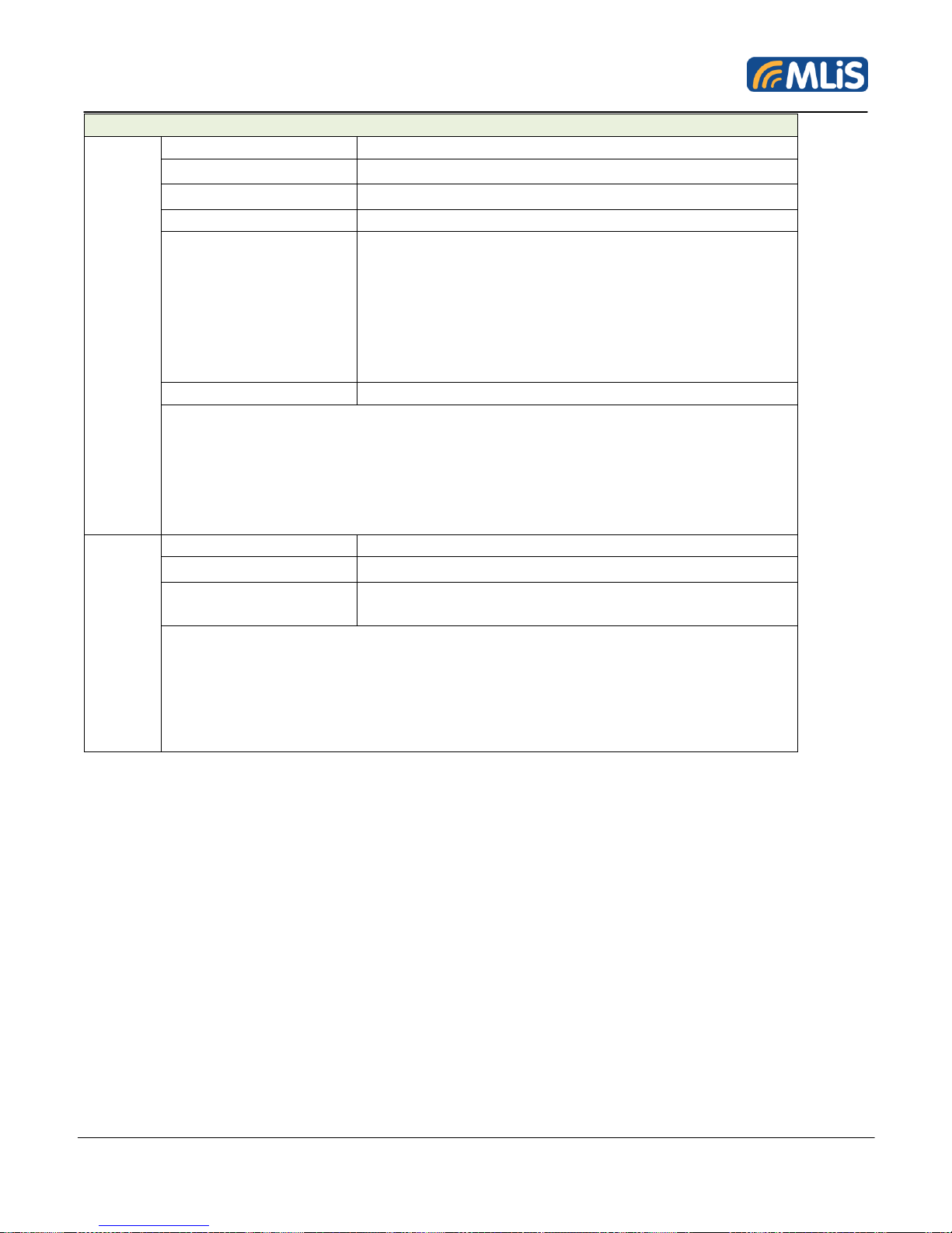
Internet Setting
Write
Command Header
MLB-INTERNETSETTING
APN
User Name
Maximum 31 chars
Password
Maximum 31 chars
Internet Service
Type
1. Transparent Client Packing Mode
2. Transparent Client Fast Mode
3. Transparent Server Packing Mode
4. Transparent Server Fast Mode
5. Socket UDP Client Mode
6. Socket TCP Client Mode
7. Socket TCP Server Mode
End Tag
Z
Example:
MLB-INTERNETSETTING: internet, user123, pass456, 2, Z
set APN = "internet" // User Name = "user123" //
Password = "pass456"
Internet connection type = "Transparent Client Fast Mode"
Read
Command Header
MLB+INTERNETSETTING
End Tag
Z
Response format
Response +: {APN}, {User Name}, {Password},
{Internet connection type }
Example:
Send --> MLB+INTERNETSETTING: Z
Response +: internet, user, pass, 4 (APN=internet /User Name =
user/Password=pass/Current Service Type is Transparent Server Fast
Mode)"
MLB-G4201 Wireless Terminal User Manual 43 Rev 1.1
Page 44
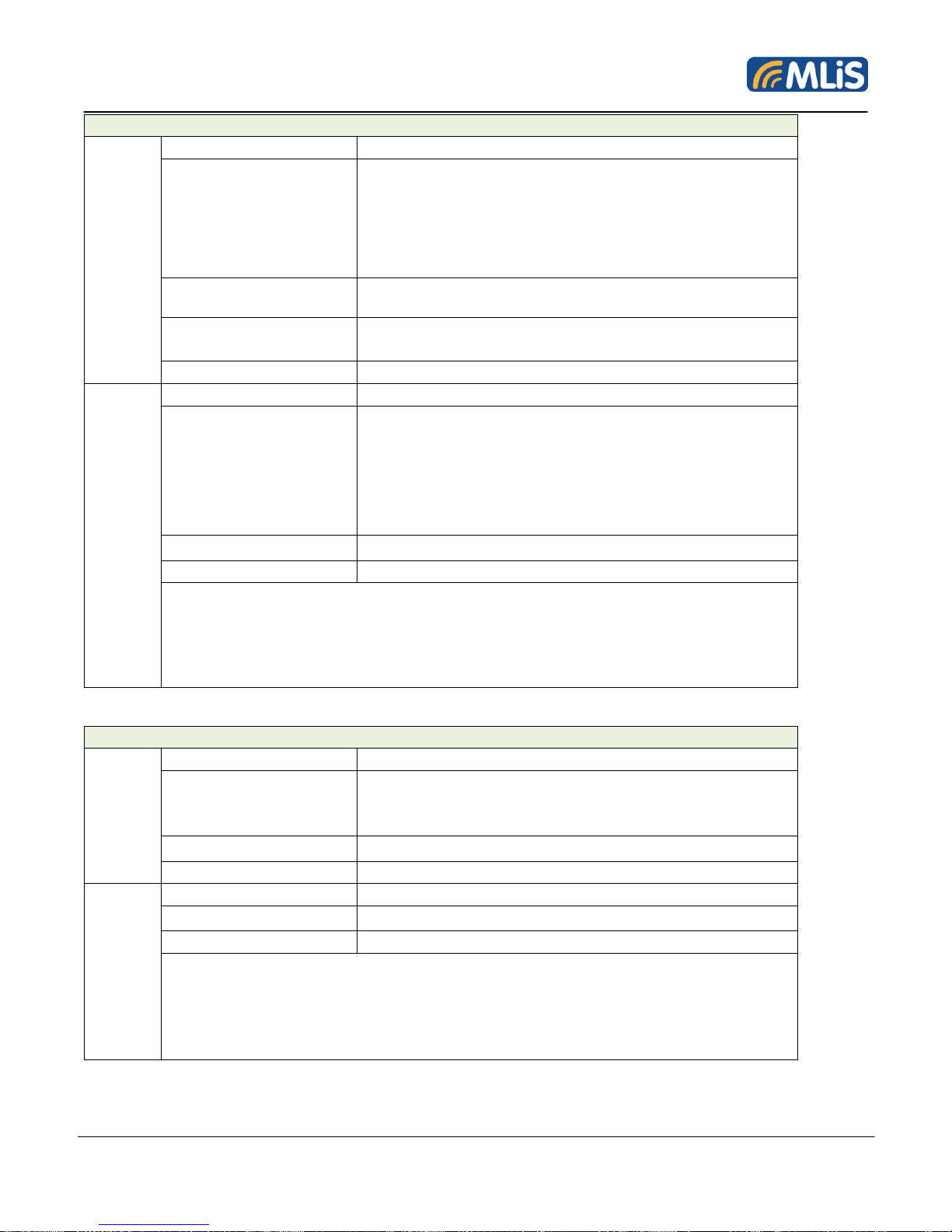
Phone Setting
Write
Command Header
MLB-PHONESETTING
Phone Event
1. Reboot
2. Connection Off-Line
3. DIO1 Event
4. DIO2 Event
5. Relay Event
6. Admin
Phone Number
Format: +886 935123456
Maximum 19 chars
Enabled
0. Disabled
1. Enabled
End Tag
Z
Read
Command Header
MLB+PHONESETTING:
Phone Event
1. Reboot
2. Connection Off-Line
3. DIO1 Event
4. DIO2 Event
5. Relay Event
6. Admin
End Tag
Z
Response format
Response +: {Phone Number}, {Phone Event}
Example:
Send --> MLB+PHONESETTING: 2, Z
Response +: +886935123456,1
(+886935123456 is the event of Off-Line that has been enabled)"
Reconnect Setting
Write
Command Header
MLB-RECONNECTSETTING:
Connection Retry
Time
0. No Retry
9999. No limitation
Range (0 ~ 9999)
Retry Time Interval
Range (1 ~ 50) Minute
End Tag
Z
Read
Command Header
MLB+RECONNECTSETTING:
End Tag
Z
Response format
Response +: { Retry Time }, { Retry Time Interval }
Example:
Send --> MLB+RECONNECTSETTING: Z
Response +: 9999,5 (Connecting maximum retry time is no limit and retry
interval is 5 minutes)"
MLB-G4201 Wireless Terminal User Manual 44 Rev 1.1
Page 45
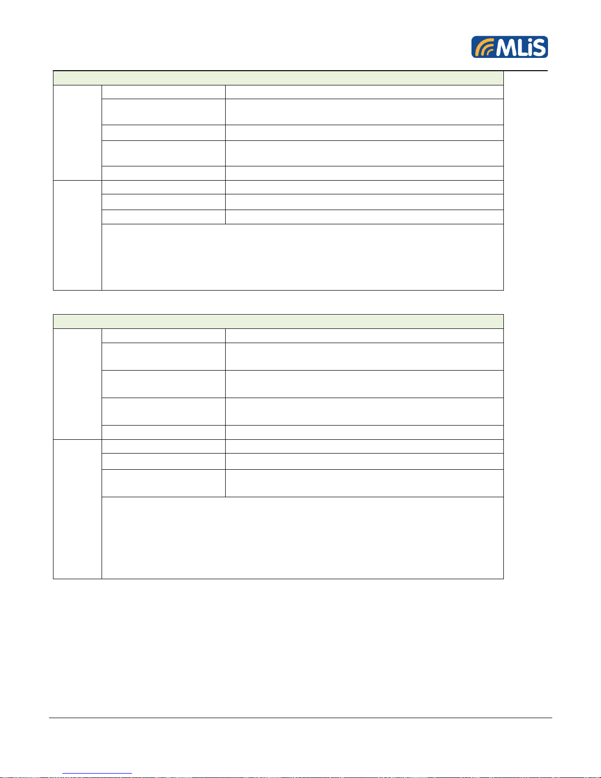
Heartbeat Setting
Write
Command Header
MLB-HEARTBEATSETTING
Heart Beat Time
0. No Heart Beat
Range (0 ~ 9999) Second
Heart Beat String
Maximum 15 chars
Sending Type
0. Send to profile 0
1. Send to all profiles
End Tag
Z
Read
Command Header
MLB+RECONNECTSETTING:
End Tag
Z
Response format
Response +: { Retry Time }, { Retry Time Interval }
Example:
Send --> MLB+RECONNECTSETTING: Z
Response +: 9999,5
(Connecting maximum retry time is no limit and retry interval is 5 minutes)"
Packing Setting
Write
Command Header
MLB-PACKINGSETTING:
Device ID
ex: Hello
Maximum 19 chars
Packing Header
ex: 123
Maximum 3 chars
Packing Enabled bit
0: Disabled
1: Enabled
End Tag
Z
Read
Command Header
MLB+PACKINGSETTING:
End Tag
Z
Response format
Response +: {ID}, {Header}, {Packing
(Enable/Disable)}
Example:
Send --> MLB+PACKINGSETTING: Z
Response +:ID_123,MST,1
(The device ID is " "ID_123"") (Packing header will be ""MST"" and has
been enabled)"
MLB-G4201 Wireless Terminal User Manual 45 Rev 1.1
Page 46

Report DIO Setting
Write
Command Header
MLB-REPORTDIOXSETTING
Report path
1. Via SMS
2. Via Internet
End Tag
Z
Read
Command Header
MLB+REPORTDIOXSETTING
End Tag
Z
Response Format
Response +: { Retry Time }, { Retry Time Interval }
Example:
Send --> MLB+REPORTDIOXSETTING: Z
Response +: SMS
(The DIO status will be reported via SMS)
Get DIO
Write
Command Header
MLB-GETDIOX
DIO Number
1. DIO1
2. DIO2
End Tag
Z
Set Relay
Write
Command Header
MLB-SETRELAY
Relay Level
0. Low
1. High
End Tag
Z
Save Parameters
Write
Command Header
MLB-SAVEPARAMETERS:
End Tag
Z
Restart
Write
Command Header
MLB-RESTART:
End Tag
Z
MLB-G4201 Wireless Terminal User Manual 46 Rev 1.1
Page 47
SALES CONTACT
Website : www.schmidtm2m.com
Taiwan
Schmidt & Co., (Hong Kong) Limited
5/F, 139 Song Jiang Road, Taipei 104, Taiwan
T (886-2) 2502-5095
F (886-2) 2502-6717
E [email protected]
Shenzhen,
China
Schmidt & Co., (China) Ltd. Shenzhen Branch
Schmidt (Shenzhen) Co., Ltd
3/F Unit E, International Culture Building,
Fu Tian Road,
Shenzhen 518033
T (86-755) 8376-0232
F (86-755) 8376-0025
E [email protected]
Singapore
Schmidt Electronics (S.E.A.) Pte Ltd
158 Kallang Way #06-10, Performance Building Singapore 349245
T (65) 6272-7233
F (65) 6273-4750
E [email protected]
MLB-G4201 Wireless Terminal User Manual 47 Rev 1.1
Page 48

7 ORDERING INFORMATION
MLiS Product
MLB-G4201: The MLIS Dual-Band 2G/3G wireless terminal
Power Adaptor
MLA-PSP-100: Input: AC 100 ~ 240V Output: 9V/1.3A DC jack 5.5/2.1
MLA-PSP-101: US Adapter Plug
MLA-PSP-104: British Adapter Plug
MLA-PSP-103: European Adapter Plug
MLA-PSP-102: Australia Adapter Plug
MLA-CAB-001: DC Jack power line 5.5/2.1
Cable
MLA-CAB-101: DB9 connector for RS232 (female)
Antenna
MLA-ANT-002: Magnet standalone antenna
MLA-ANT-001: PCB antenna
MLA-ANT-005: Magnet 850/900MHz-1800/1900MHz -2100MHz
5- band antenna with male SMA connector1.5dBi
MLB-G4201 Wireless Terminal User Manual 48 Rev 1.1
Page 49

Regional Contact
Taiwan | +886 2-2502-5095
China | +86 (755) 8376-0232
Singapore | +65 6272-7233
Email | [email protected]
Official Website
MLiS Website | www.schmidtm2m.com
Support | www.schmidtm2m.com/support
Download | www.schmidtm2m.com/download
Facebook | www.facebook.com/MLiSM2M
MLB-G4201 Wireless Terminal User Manual 49 Rev 1.1
 Loading...