

Page 1

MLB-E4203-28-F,
MLB-E4204-28-G-F
28-Ports L2 Managed
(Gigabit) Switch
USER MANNUAL
Page 2

2
Managed Switch series
MLB-E4203-28-F / MLB-E4204-28-G-F
Managed Industrial Ethernet Switch
User Manual
Part Number:
Issue: 01, May 2015
Page 3

CONTENTS
i
[CONTENTS]
Preface ................................................................................................................................................ 3
Scope ................................................................................................................................................. 3
Audience ............................................................................................................................................ 3
Safety Instructions.............................................................................................................................. 3
Documentation Conventions .............................................................................................................. 3
Overview ............................................................................................................................................. 7
Package Checklist.............................................................................................................................. 7
Safety Instructions.............................................................................................................................. 7
Model Layouts .................................................................................................................................... 8
Dimensions ...................................................................................................................................... 10
Technical Specifications .................................................................................................................... 11
Quick Installation ............................................................................................................................. 13
Mounting the RACK-MOUNT SWITCH ........................................................................................... 13
Ground Connecting .......................................................................................................................... 14
Alarm Relay Connecting .................................................................................................................. 15
Power Connecting ............................................................................................................................ 15
Ethernet Interface Connecting (RJ45 Ethernet) .............................................................................. 15
Connecting the Ethernet Interface (Fiber) ....................................................................................... 16
Console Connection ......................................................................................................................... 17
Connect & Login to MLB-E4203-28-F / MLB-E4204-28-G-F .......................................................... 17
CLI Initialization & Configuration (Optional) ..................................................................................... 18
SYSTEM RESET ............................................................................................................................. 18
LED STATUS INDICATIONS ........................................................................................................... 19
Web Interface Initialization (Optional) .............................................................................................. 20
VLAN Application Guide ................................................................................................................. 22
Example 1: Default VLAN Settings .................................................................................................. 22
Example 2: Port-based VLANs ........................................................................................................ 23
Example 3: IEEE 802.1Q Tagging ................................................................................................... 26
Security Application Guide ............................................................................................................. 29
Case 1: ACL for MAC address ......................................................................................................... 29
Case 2: ACL for IP address.............................................................................................................. 45
Case 3: ACL for L4 Port ................................................................................................................... 45
Case 4: ACL for ToS ......................................................................................................................... 45
Ring Version 2 Application Guide ................................................................................................. 46
Ring Version 2 Feature .................................................................................................................... 47
Configuration (Web Interface) .......................................................................................................... 50
QoS Application Guide ................................................................................................................... 56
SP/SPWRR/WRR ............................................................................................................................ 56
Example 1: SPQ without Shaping (Default profile) .......................................................................... 57
Example 2: SPQ with Shaping ......................................................................................................... 59
Example 3: WRR .............................................................................................................................. 61
Example 4 SP-WRR ........................................................................................................................ 65
Link Fail Alarm Application Guide ................................................................................................. 73
Introduction of Alarm function .......................................................................................................... 73
Link Fail Alarm in RACK-MOUNT SWITCH ..................................................................................... 73
802.1x Authentication Application Guide ..................................................................................... 78
Introduction of 802.1x authentication function ................................................................................. 78
802.1x Timer in RACK-MOUNT SWITCH........................................................................................ 78
Configuration in RADIUS Server ..................................................................................................... 78
Example ........................................................................................................................................... 79
Page 4

CONTENTS
ii
Page 5

1
Preface
Scope
Audience
Safety Instructions
Documentation Conventions
Page 6

2
Page 7

Preface
3
Preface
Scope
This document provides an overview on RACK-MOUNT SWITCH. It contains:
Descriptive material about the RACK-MOUNT SWITCH Quick Installation Guide.
Descriptive material about the RACK-MOUNT SWITCH Application Guide.
Audience
The guide is intended for system engineers or operating personnel who want to have a basic
understanding of RACK-MOUNT SWITCH.
Safety Instructions
When a connector is removed during installation, testing, or servicing, or when an energized fiber is
broken, a risk of ocular exposure to optical energy that may be potentially hazardous occurs, depending
on the laser output power.
The primary hazards of exposure to laser radiation from an optical-fiber communication system are:
Damage to the eye by accidental exposure to a beam emitted by a laser source.
Damage to the eye from viewing a connector attached to a broken fiber or an energized fiber.
Documentation Conventions
The following conventions are used in this manual to emphasize information that will be of interest to the
reader.
Danger — The described activity or situation might or will cause personal injury.
Warning — The described activity or situation might or will cause equipment damage.
Caution — The described activity or situation might or will cause service interruption.
Note — The information supplements the text or highlights important points.
Page 8

Preface
4
Page 9

5
Overview
Overview
Panel Introduction
Technical Specifications
Page 10

6
Page 11
Quick Installation
7
Overview
This document provides quick installation on MLB-E4204-28-G-F.
Package Checklist
Please verify that the box contains the following items:
Item
Quantity
Rack-mount Ethernet switch
1
Rack-mount bracket
2
Screws (for bracket)
6
DC power terminal block (4-pin) – option for DC models
1
ALM terminal block (2-pin)
1
Quick Installation Guide
1
RJ45 Ethernet port Dust Cover
14
SFP Ethernet port Dust cover
2
Safety Instructions
When a connector is removed during installation, testing, or servicing, or when an energized fiber is
broken, a risk of ocular exposure to optical energy that may be potentially hazardous occurs,
depending on the laser output power.
The primary hazards of exposure to laser radiation from an optical-fiber communication system are:
Damage to the eye by accidental exposure to a beam emitted by a laser source.
Damage to the eye from viewing a connector attached to a broken fiber or an energized fiber.
Page 12

Quick Installation
8
Model Layouts
Front Access Models
Front View
All Front Access models
Rear View
MLB-E4204-28-G-F
Page 13
Quick Installation
9
Front view
Rear view
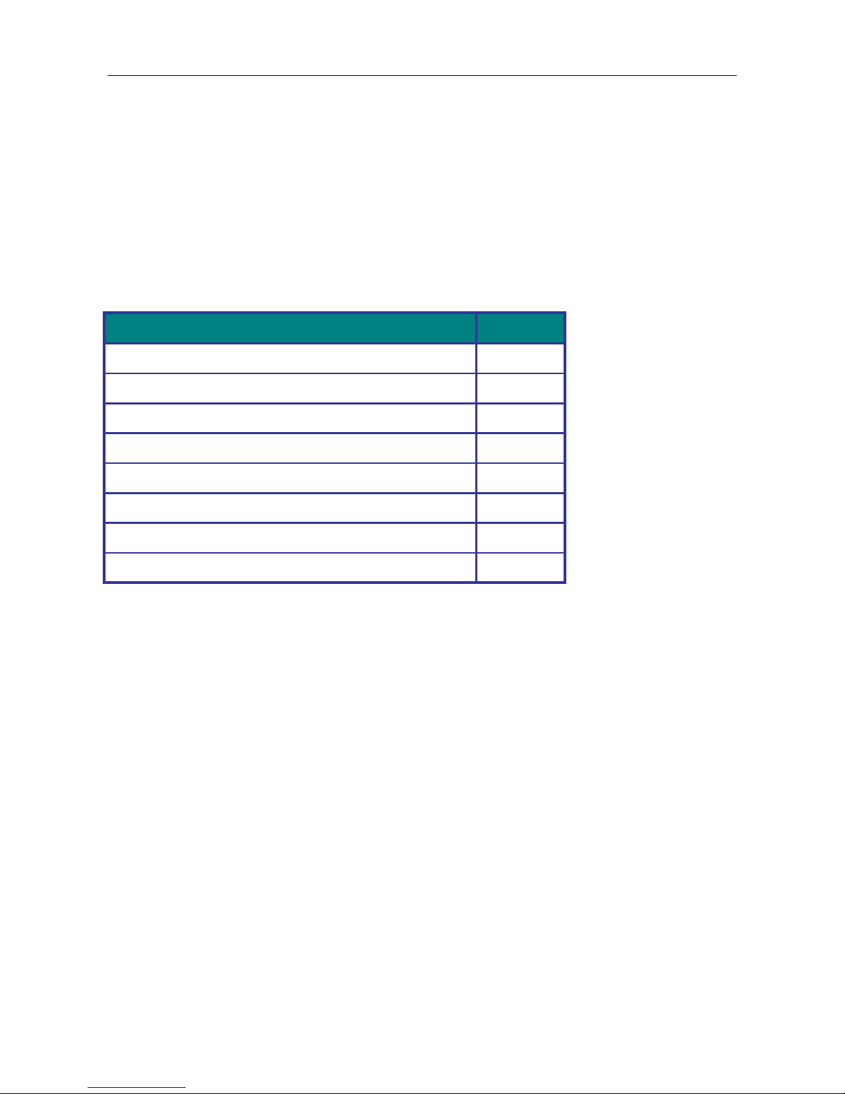
System Status Indicators (LED)
Port Status Indicators (LED)
Gigabit Copper RJ45 ports
100/1000BaseSFP slot (Port 25 & 26)
1000BaseSFP slot (Port 27 & 28)
Terminal block for Alarm Relay output
Grounding screw
DC terminal block (dual input)
AC supply socket
Console port
Reset Button
Page 14

Quick Installation
10
Dimensions
(unit = mm)
Page 15

Quick Installation
11
Technical Specifications
Ethernet Interface
Ethernet Interface
24 Gigabit Copper ports plus 4 100FX / 1000BaseF
(SX/LX/LH/ZX/EZX)
Operating mode
Store and forward, L2 wire-speed/non-blocking switching engine
Copper RJ45 Ports
Speed
10/100/1000 Mbps
MDI/MDIX Auto-crossover
Support straight or cross wired cables
Auto-negotiating
10/100/1000 Mbps speed auto-negotiation; Full and half duplex
SFP (pluggable) Ports
Port types supported
Gigabit fiber multimode, fiber single mode, fiber long-haul
single mode 100/1000BaseF (SX/LX/LH/ZX/EZX)
Fiber port connector
LC typically for fiber (depends on module)
Power
Power input options
DC Redundant Input Terminals & Reverse power protection
Single/dual AC inputs
DC & AC dual inputs
Input voltage range
AC: 100/240 VAC, 50Hz ~ 60Hz
Power Consumption
24 W (Max.)
Environmental and Compliances
Operating temperature range
0 to 60°C or -40 to +75°C (cold startup at -40°C)
Storage temperature range
-40 to +85 °C
Humidity (non-condensing)
5 to 95% RH
Vibration, shock & freefall
Vibration: IEC60068-2-6; Shock: IEC60068-2-27; Free Fall:
IEC60068-2-32
Certification compliance
CE/FCC
RoHS and WEEE
RoHS (Pb free) and WEEE compliant
MTBF
> 25 years
Mechanical
Ingress protection
IP30
Dimensions
440 (W) x 44 (H) x 253 (D) mm
Weight
3.2 kg (Max.)
Installation option
19’’/23’’ rack mounting
Page 16

Quick Installation
12
Quick Installation
Equipment Mounting
Cable Connecting
Equipment Configuration
Page 17
Quick Installation
13
Quick Installation
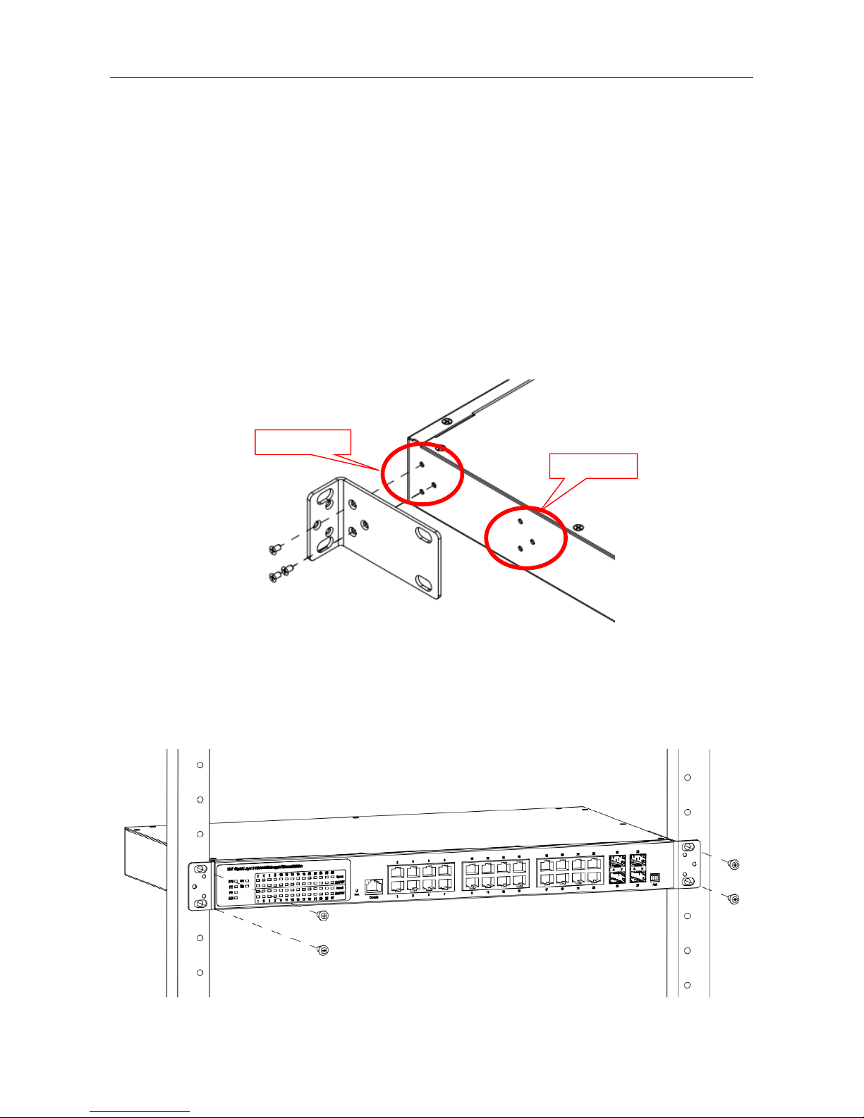
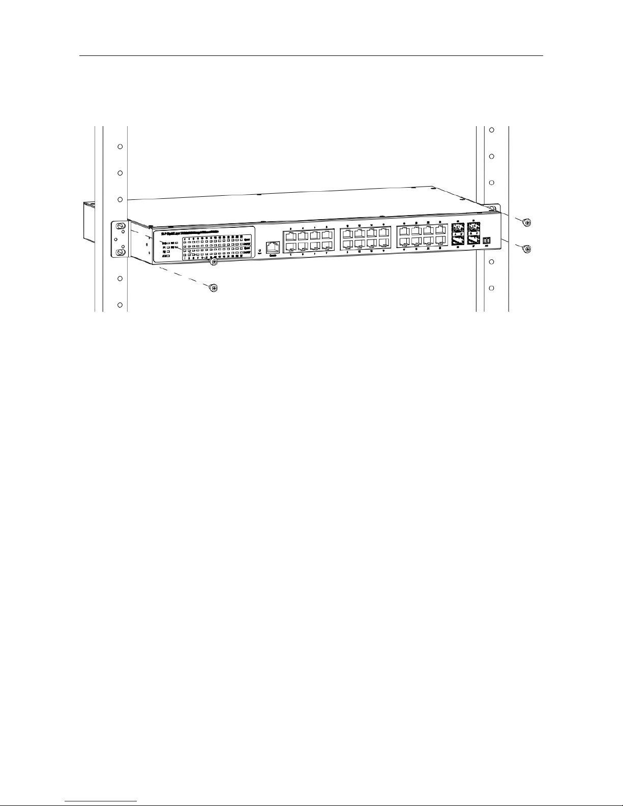
Mounting the RACK-MOUNT SWITCH
When mounting the switch, practice good safety habits. Relay rack mounting normally requires at
least two people.
1. Obtain the tools required for the mounting hardware.
2. Attach the mounting brackets to the switch by using the screws in the accessory kit.
3. From the front of the relay rack, position the switch in its relay rack mounting location.
4. Secure the switch in its relay location on both left and right side of mounting bracket.
Position 1
Position 2
Page 18
Quick Installation
14
Mounting Bracket Position 1 for Standard Mount
Mounting Bracket Position 2 for Standard Mount
Ground Connecting
MLB-E4204-28-G-F must be properly grounded for optimum system performance.
Page 19

Quick Installation
15
Alarm Relay Connecting
The alarm relay output contacts with current carrying capacity of 30VDC, 1A are a 2P terminal block.
The alarm relay contact is “Normal Open”, and it will be closed when detected any power failures.
Power Connecting
DC Power Connection
The switch can be powered from two power supply (input range 12V – 58V). The DC power
connector is a 4P terminal block; insert the positive and negative wires into V+ and V- contact on the
terminal block and tighten the wire-clamp screws to prevent the wires from being loosened.
After completing chassis installation, please apply power to the fused power distribution panel
feeding the chassis.
Note
The DC power should be connected to a well-fused power supply.
AC Power Connection
If you use AC power, connect the AC power cord to the AC supply socket on the rear panel, and
plug the cord into the external power source. The voltage must be 100 to 240 V (±10% tolerance).
Warning:
Ensure that all power sources to the chassis (power distribution panel) are turned off
during the connection.
Ethernet Interface Connecting (RJ45 Ethernet)
MLB-E4204-28-G-F provides two types of electrical (RJ45) and optical (mini-GBIC) interfaces.
Connecting the Ethernet interface via RJ45:
To connect to a PC, use a straight-through or a cross-over Ethernet cable,
To connect the switch to an Ethernet device, use UTP (Unshielded Twisted Pair) or STP
(Shielded Twisted Pair) Ethernet cables.
Page 20
Quick Installation
16
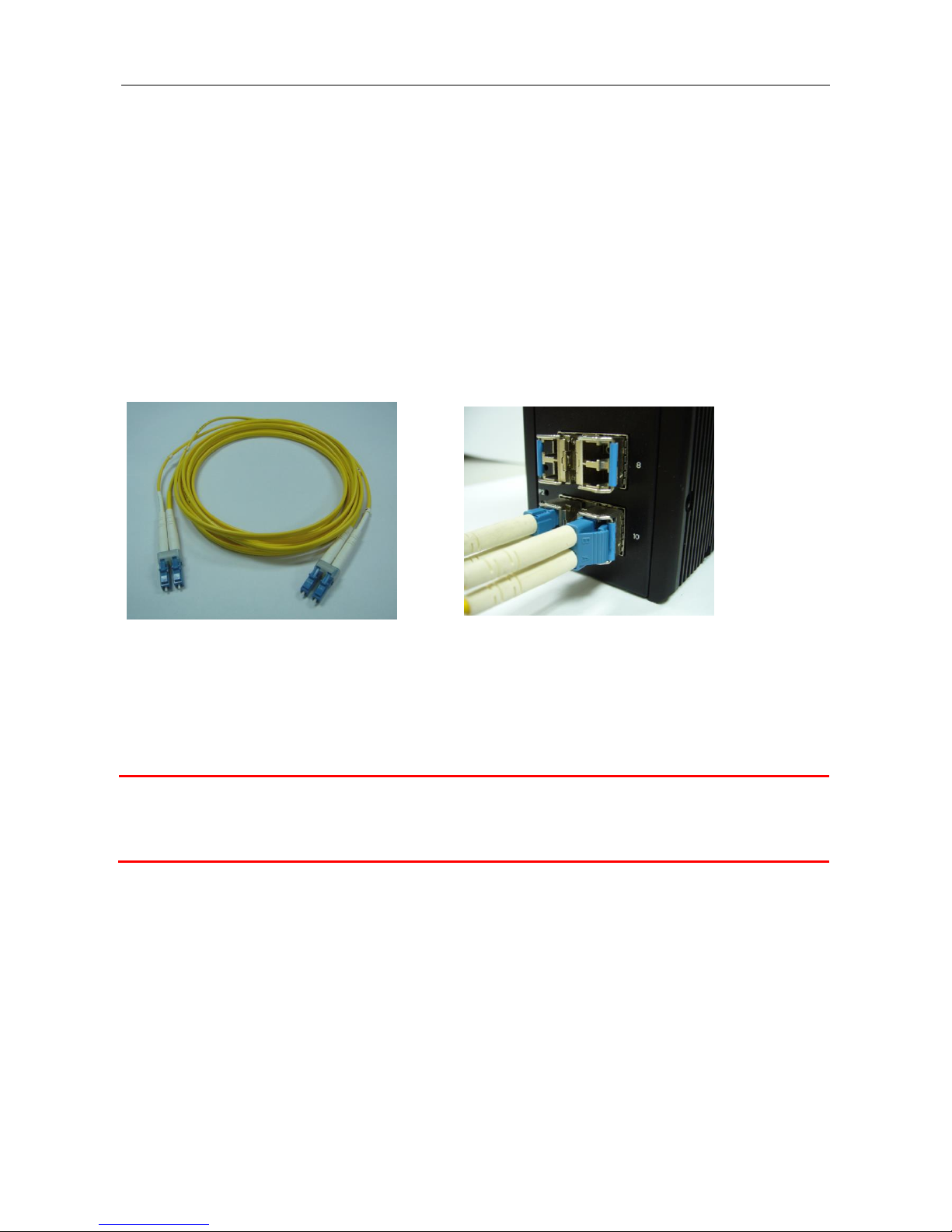
Connecting the Ethernet Interface (Fiber)
For a 1000 Mbps fiber port available, please use the mini-GBIC SFP. These accept plug in fiber
transceivers that typically have an LC style connector.
For a 100 Mbps fiber port available, please prepare the LC connectors or SC connectors (with the
use of an optional SC-to-LC adapter).
They are available with multimode, single mode, long-haul or special-application transceivers.
Prepare a proper SFP module and install it into the optical port. Then you can connect fiber optics
cabling that uses LC connectors or SC connectors (with the use of an optional SC-to-LC adapter) to the
fiber optics connector.
Fiber optics cable with LC duplex
connector
Connect the optical fiber to the SFP
socket
DANGER:
Never attempt to view optical connectors that might be emitting laser energy.
Do not power up the laser product without connecting the laser to the optical fiber and
putting the cover in position, as laser outputs will emit infrared laser light at this point.
Page 21
Quick Installation
17
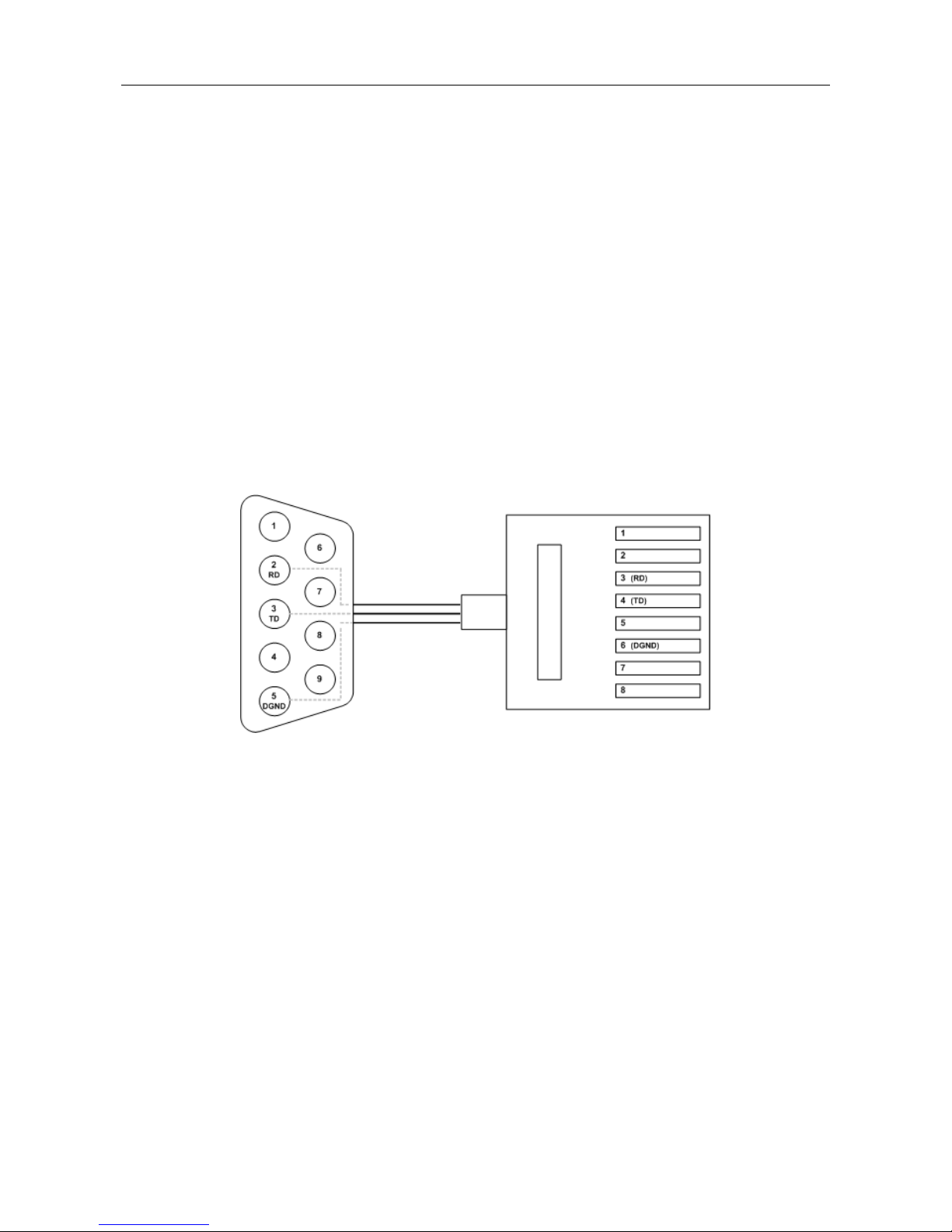
Console Connection
The Console port is for local management by using a terminal emulator or a computer with terminal
emulation software.
DB9 connector connect to computer COM port
Baud rate: 115200bps
8 data bits, 1 stop bit
None Priority
None flow control
To connect the host PC to the console port, a RJ45 (male) connector-to-RS232 DB9 (female)
connector cable is required. The RJ45 connector of the cable is connected to the console port of
MLB-E4204-28-G-F; the DB9 connector of the cable is connected to the PC COM port. The pin
assignment of the console cable is shown below:
Connect & Login to MLB-E4203-28-F / MLB-E4204-28-G-F
1. Connecting to MLB-E4203-28-F / MLB-E4204-28-G-F Ethernet port (RJ45 Ethernet port).
2. Factory default IP: 192.168.0.1
3. Login with default account and password.
Username: admin
Password:
Page 22
Quick Installation
18
CLI Initialization & Configuration (Optional)
1. Connecting to MLB-E4203-28-F / MLB-E4204-28-G-F Ethernet port (RJ45 Ethernet port).
2. Key-in the command under Telnet: telnet 192.168.0.1
3. Login with default account and password.
Username: admin
Password:
4. Change the IP with commands listed below:
CLI Command:
SYSTEM RESET
The Reset button is provided to reboot the system without the need to remove power. Under normal
circumstances, you will not have to use it. However, or rare occasions, the MLB-E4203-28-F /
MLB-E4204-28-G-F may not respond; then you may need to push the Reset button.
enable
configure
interface vlan 1
ip-address xxx.xxx.xxx.xxx netmask xxx.xxx.xxx.xxx
exit
Page 23
Quick Installation
19
LED STATUS INDICATIONS
LLEEDD NNaammee
IInnddiiccaattoorr
//ccoolloorr
CCoonnddiittiioonn
11.. SSyysstteemm SSttaattuuss IInnddiiccaattoorrs
s
SSYYS
S
OOnn GGrreeeenn
SSyysstteemm iiss wwoorrkkiinngg nnoorrmmaall
FFllaasshh GGrreeeenn
SSyysstteemm bboooottiinngg,, oorr ddaattaabbaassee ssaavviinngg oorr rreemmoottee ddoowwnnllooaadd iiss
iinn--pprrooggrreessss
OOffff SSyysstteemm iiss nnoott wwoorrkkiinngg oorr nnoott hhaavvee ssuuppppllyy ppoowweerr
PP11
OOnn GGrreeeenn
PP11 ppoowweerr lliinnee hhaass ppoowweerr
FFllaasshhiinngg GGrreeeenn
PP11 iiss DDCC ppoowweerr aanndd oonnllyy oonnee ppaaiirr ooff ppoowweerr iiss iinnppuutt
OOffff PP11 ppoowweerr lliinnee ddiissccoonnnneecctt oorr ddooeess nnoott hhaavvee ssuuppppllyy ppoowweerr
PP22
OOnn GGrreeeenn
PP22 ppoowweerr lliinnee hhaass ppoowweerr
OOffff PP22 ppoowweerr lliinnee ddiissccoonnnneecctt oorr ddooeess nnoott hhaavvee ssuuppppllyy ppoowweerr
AAllaarrmm
OOnn RReedd
AAllaarrmm eevveenntt ooccccuurrss
OOffff NNoo aallaarrmm
RRRR ((RRiinngg RRoollee)
)
OOnn GGrreeeenn
OOnnee ooff 33 RRiinngg ggrroouupp iinn MMaasstteerr aanndd EEnnaabbllee mmooddee
OOffff RRiinngg ggrroouupp nnoott sseett oorr ddiissaabbllee
RRSS ((RRiinngg SSttaattuuss)
)
FFllaasshh GGrreeeenn
RRiinngg ffaaiill hhaappppeenn aanndd ddeetteecctteedd
OOffff NNoo rriinngg ffaaiill ddeetteecctteedd
22.. PPoorrtt SSttaattuuss IInnddiiccaattoorrs
s
CCooppppeerr ppoorrtt LLiinnkk//AAcct
t
((PPoorrtt 11 ttoo 2244)
)
OOnn GGrreeeenn
EEtthheerrnneett lliinnkk uupp bbuutt nnoo ttrraaffffiicc iiss ddeetteecctteedd
FFllaasshhiinngg GGrreeeenn
EEtthheerrnneett lliinnkk uupp aanndd tthheerree iiss ttrraaffffiicc ddeetteecctteedd
OOffff EEtthheerrnneett lliinnkk ddoowwnn
CCooppppeerr ppoorrtt SSppeeeed
d
((PPoorrtt 11 ttoo 2244)
)
OOnn YYeellllooww
AA 110000MMbbppss ccoonnnneeccttiioonn iiss ddeetteecctteedd
OOffff NNoo lliinnkk oorr aa 1100 MMbbppss,,110000MMbbppss ccoonnnneeccttiioonn iiss ddeetteecctteedd
SSFFPP ppoorrtt LLiinnk
k
((PPoorrtt 2255 ttoo 2288))
OOnn GGrreeeen
n
EEtthheerrnneett lliinnkk uupp
FFllaasshhiinngg GGrreeeenn
EEtthheerrnneett lliinnkk uupp aanndd tthheerree iiss ttrraaffffiicc ddeetteecctteedd
OOfff
f
EEtthheerrnneett lliinnkk ddoowwnn
SSFFPP SSppeeeedd ((110000MM)
)
((PPoorrtt 2255 ttoo 2288)
)
OOnn SSFFPP ppoorrtt ssppeeeedd 110000MMbbppss
OOffff SSFFPP ppoorrtt ssppeeeedd 110000MMbbppss oorr lliinnkk ddoowwn
n
Page 24
Quick Installation
20
Web Interface Initialization (Optional)
Web Browser Support
IE 7 (or newer version) with the following default settings is recommended:
Language script
Latin based
Web page font
Times New Roman
Plain text font
Courier New
Encoding
Unicode (UTF-8)
Text size
Medium
Firefox with the following default settings is recommended:
Web page font
Times New Roman
Encoding
Unicode (UTF-8)
Text size
16
Google Chrome with the following default settings is recommended:
Web page font
Times New Roman
Encoding
Unicode (UTF-8)
Text size
Medium
Page 25

VLAN Application Guide
21
Application Guide
VLAN Application Guide
Security Application Guide
Ring Protection Application Guide
QoS Application Guide
Link Fail Alarm Application Guide
802.1x Authentication Application Guide
Page 26
VLAN Application Guide
22
VLAN Application Guide
This part describes how to configure Virtual LANs (VLANs) in RACK-MOUNT SWITCH. The
RACK-MOUNT SWITCH supports up to 2048 VLANs. Ports are grouped into broadcast domains by
assigning them to the same VLAN. Frames received in on VLAN can only be forwarded within that VLAN,
and multicast frames and unknown unicast frames are flooded only to ports in the same VLAN.
Example 1: Default VLAN Settings
Each port in the RACK-MOUNT SWITCH has a configurable default VLAN number, known as its PVID.
This places all ports on the same VLAN initially, although each port PVID is configurable to any VLAN
number between 1 and 4094.
The default configuration settings for RACK-MOUNT SWITCH have all ports set as untagged members
of VLAN 1 with all ports configured as PVID=1. In default configuration example shown in the following
figure, all incoming packets are assigned to VLAN 1 by the default port VLAN identifier (PVID=1).
Page 27

VLAN Application Guide
23
Example 2: Port-based VLANs
When the RACK-MOUNT SWITCH receives an untagged VLAN packet, it will add a VLAN tag to the
frame according to the PVID setting on a port. As shown in the following figure, the untagged packet is
marked (tagged) as it leaves the RACK-MOUNT SWITCH through Port 2, which is configured as a
tagged member of VLAN100. The untagged packet remains unchanged as it leaves the RACK-MOUNT
SWITCH through Port 7, which is configured as an untagged member of VLAN100.
Configuration:
Step1. Go to Configuration -> Port Configuration -> Bridge Port and configure PVID 100 on Port 1, Port
2 and Port 7.
Page 28

VLAN Application Guide
24
Step2. Select Configuration -> VLAN -> Static VLAN. Create a VLAN with VLAN ID 100. Enter a VLAN
name in the Name field.
Step3. Assign VLAN tag setting to or remove it from a port by toggling the check box under an individual
port number. The tag settings determine if packets that are transmitted from the port tagged or untagged
with the VLAN ID. The possible tag settings are:
T
Specifies that the egress packet is tagged for the port.
U
Specifies that the egress packet is untagged for the port.
▬
Specifies that the port is not part of the VLAN.
Here we set tagged VLAN100 on Port 1 and Port 2, untagged VLAN100 on Port7.
Step4. Transmit untagged unicast packets from Port 1 to Port 2 and Port 7. The RACK-MOUNT
SWITCH should tag it with VID 100. The packet has access to Port2 and Port 7. The outgoing packet is
stripped of its tag to leave Port 7 as an untagged packet. For Port 2, the outgoing packet leaves as a
Page 29

VLAN Application Guide
25
tagged packet with VID 100.
Step5. Transmit untagged unicast packets from Port 2 to Port 1 and Port 7. The RACK-MOUNT
SWITCH should tag it with VID 100. The packet has access to Port1 and Port 7. The outgoing packet is
stripped of its tag to leave Port 7 as an untagged packet. For Port 1, the outgoing packet leaves as a
tagged packet with VID 100.
Step6. Transmit untagged unicast packets from Port 7 to Port 1 and Port 2. The RACK-MOUNT
SWITCH should tag it with VID 100. The packet has access to Port1 and Port 2. For Port 1 and Port 2,
the outgoing packet leaves as a tagged packet with VID 100.
Step7. Repeat step 4 using broadcast and multicast packets.
CLI Command:
interface gigabit 1
default vlan 100
vlan 100 tag
exit
interface gigabit 2
default vlan 100
vlan 100 tag
exit
interface gigabit 7
default vlan 100
vlan 100 untag
exit
Page 30

VLAN Application Guide
26
Example 3: IEEE 802.1Q Tagging
RACK-MOUNT SWITCH is able to construct layer-2 broadcast domain by identifying VLAN ID specified
by IEEE 802.1Q. It forwards a frame between bridge ports assigned to the same VLAN ID and can set
multiple VLANs on each bridge port.
In the following figure, the tagged incoming packets are assigned directly to VLAN 100 and VLAN 200
because of the tag assignment in the packet. Port 2 is configured as a tagged member of VLAN 100, and
Port 7 is configured as an untagged member of VLAN 200. Hosts in the same VLAN communicate with
each other as if they in a LAN. However, hosts in different VLANs cannot communicate with each other
directly.
In this case:
1. The hosts from Group A can communicate with each other.
2. The hosts from Group B can communicate with each other.
3. The hosts of Group A and Group B can’t communicate with each other.
4. Both the Group A and Group B can go to Internet through RACK-MOUNT SWITCH.
Page 31

VLAN Application Guide
27
Configuration:
Step1. Go to Configuration ->VLAN -> Static VLAN page specify the VLAN membership as follows:
Step2. Transmit unicast packets with VLAN tag 100 from Port 1 to Port 2 and Port 7. The RACK-MOUNT
SWITCH should tag it with VID 100. The packet only has access to Port2. For Port 2, the outgoing
packet leaves as a tagged packet with VID 100.
Step3. Transmit unicast packets with VLAN tag 200 from Port 1 to Port 2 and Port 7. The RACK-MOUNT
SWITCH should tag it with VID 200. The packet only has access to Port7. The outgoing packet on Port 7
is stripped of its tag as an untagged packet.
Step4. Transmit unicast packets with VLAN tag 100 from Port 2 to Port 1 and Port 7. The RACK-MOUNT
SWITCH should tag it with VID 100. The packet only has access to Port1. For Port 1, the outgoing
packet leaves as a tagged packet with VID 100.
Step5. Transmit unicast packets with VLAN tag 200 from Port 7 to Port 1 and Port 2. The RACK-MOUNT
SWITCH should tag it with VID 200. The packet only has access to Port1. The outgoing packet on Port 1
will leave as a tagged packet with VID 200.
Step6. Repeat the above steps using broadcast and multicast packets.
CLI Command:
Page 32

VLAN Application Guide
28
vlan 100 v100
vlan 200 v200
interface gigabit 1
vlan 100 tag
vlan 200 tag
exit
interface gigabit 2
vlan 100 tag
exit
interface gigabit 7
vlan 200 untag
exit
Page 33

QoS Application Guide
29
Security Application Guide
ACL function supports access control security for MAC address, IP address, Layer4 Port, and Type of
Service. Each has five actions: Deny, Permit, Queue Mapping, CoS Marking, and Copy Frame. User can
set default ACL rule to Permit or Deny. To get more clearly for these ACL function, see following table.
Default ACL Rule
Actions
Deny
Permit
Queue
Mapping
CoS Marking
Copy Frame
Permit
(a)
(b)
(c)
(d)
(e)
Deny
(f)
(g)
(h)
(i)
(j)
Brief descriptions of the above table:
(a): Permit all frames, but deny frames set in ACL entry.
(b): Permit all frames.
(c): Permit all frames, and to do queue mapping of the transmitting frames.
(d): Permit all frames, and to change CoS value of the transmitting frames.
(e): Permit all frames, and to copy frame which set in ACL entry to a defined GE port.
(f): Deny all frames.
(g): Deny all frames, but permit frames set in ACL entry.
(h): Deny all frames.
(i): Deny all frames.
(j): Deny all frames, but to copy frame which set in ACL entry to a defined GE port.
Case 1: ACL for MAC address
For MAC address ACL, it can filter on source MAC address, destination MAC address, or both. When it
filters on both MAC address, packets coincident with both rules will take effect. In other words, it does
not do filter if it only coincident with one rule.
If user want to filter only one directional MAC address, the other MAC address just set to all zero. It
means don’t care portion. Besides MAC address, it also supports VLAN and Ether type for filter
additionally. Certain VLAN or Ether type under these MAC address will take effect. If user doesn’t care
VLAN or Ether type, he can just set to zero values. Following are examples about the above table:
Case 1: (a)
User can set default ACL Rule of GE port as “Permit”, then to bind a suitable profile with “deny” action for
ACL. It means GE port can pass through all packets but not ACL entry of the profile binding.
Page 34

QoS Application Guide
30
◎ One directional MAC address with one VLAN deny filtering.
Step 1: Create a new ACL Profile. (Profile Name: DenySomeMac)
Step 2: Create a new ACL Entry rule under this ACL profile. (Deny MAC: 11 and VLAN: 4)
Step 3: Bind this ACL profile to a GE port. (GE-4)
Page 35

QoS Application Guide
31
Step 4: Send frames between GE-3 and GE-4, and see test result.
CLI Command:
profile acl
acl-profile 2 create
acl-profile 2 set name DenySomeMac
acl-profile 2 create entry 1
acl-profile 2 set entry 1 mac-type set vlan 4
acl-profile 2 set entry 1 mac-type set srcmac 00:00:00:00:00:11
FF:FF:FF:FF:FF:FF
exit
vlan 4
vlan 5
interface gigabit 3
vlan 4 tag
vlan 5 tag
exit
interface gigabit 4
vlan 4 tag
vlan 5 tag
acl-profile-bind 2
exit
RACK-
SWITCH
SWITCH
SWITCH
Page 36

QoS Application Guide
32
◎ Two directional MAC address with all VLAN deny filtering.
Step 1: Create a new ACL Profile. (Profile Name: DenySomeMac)
Step 2: Create a new ACL Entry rule under this ACL profile. (Deny SrcMAC: 13 and DesMAC: 11)
Step 3: Bind this ACL profile to a GE port. (GE-3)
Page 37

QoS Application Guide
33
Step 4: Send frames between GE-3 and GE-4, and see test result.
CLI Command:
profile acl
acl-profile 2 create
acl-profile 2 set name DenySomeMac
acl-profile 2 create entry 1
acl-profile 2 set entry 1 mac-type set srcmac 00:00:00:00:00:13 FF:FF:FF:FF:FF:FF
acl-profile 2 set entry 1 mac-type set dstmac 00:00:00:00:00:11 FF:FF:FF:FF:FF:FF
exit
vlan 4
vlan 5
interface gigabit 3
vlan 4 tag
vlan 5 tag
acl-profile-bind 2
exit
interface gigabit 4
vlan 4 tag
vlan 5 tag
exit
RACK-
RACK-
RACK-
Page 38

QoS Application Guide
34
Case 1: (b)
This case acts as no ACL function. It means all frames will pass through.
Case 1: (c)
User can set default ACL Rule of GE port as “Permit”, then to bind a suitable profile with “Queue
Mapping” action for some ACL function. It means GE port can do queue mapping 0~7 of the frame
received from this port.
Case 1: (d)
User can set default ACL Rule of GE port as “Permit”, then to bind a suitable profile with “CoS Marking”
action for some ACL function. It means GE port can remark CoS of the VLAN frame received from this
port.
◎ One directional MAC address with CoS Marking action. (one VLAN, and don’t care
Ether Type)
Step 1: Create a new ACL Profile. (Profile Name: CoSMarkingTest)
Step 2: Create a new ACL Entry rule under this ACL profile.
(Filter SrcMAC: 11 and VLAN ID: 4 frame to CoS: 2)
Step 3: Bind this ACL profile to a GE port. (GE-4)
Page 39

QoS Application Guide
35
Step 4: Send frames between GE-3 and GE-4, and see test result.
CLI Command:
profile acl
acl-profile 2 create
acl-profile 2 set name CoSMarkingTest
acl-profile 2 create entry 1
acl-profile 2 set entry 1 mac-type set vlan 4
acl-profile 2 set entry 1 mac-type set srcmac 00:00:00:00:00:11 FF:FF:FF:FF:FF:FF
acl-profile 2 set entry 1 action cos 2
exit
vlan 4
vlan 5
interface gigabit 3
vlan 4 tag
vlan 5 tag
exit
interface gigabit 4
vlan 4 tag
vlan 5 tag
acl-profile-bind 2
exit
RACK-
RACK-
RACK-
Page 40

QoS Application Guide
36
Case 1: (e)
User can set default ACL Rule of GE port as “Permit”, then to bind a suitable profile with “Copy Frame”
action for mirror analyzer used. It means the system will copy frames from binding GE Port to analyzer
port.
◎ Two directional MAC address with Copy Frame action.
(Don’t care VLAN ID, Ether Type)
Step 1: Create a new ACL Profile. (Profile Name: CopyFrameTest)
Step 2: Create a new ACL Entry rule under this ACL profile. (SrcMAC: 13 and DesMAC: 11)
Step 3: Set analyzer port to enable and mirror analyzer port.
Step 4: Bind this ACL profile to a GE port. (GE-3)
Page 41

QoS Application Guide
37
Step 5: Send frames between GE-3 and GE-4, and see test result.
CLI Command:
profile acl
acl-profile 2 create
acl-profile 2 set name CopyFrameTest
acl-profile 2 create entry 1
acl-profile 2 set entry 1 mac-type set srcmac 00:00:00:00:00:13 FF:FF:FF:FF:FF:FF
acl-profile 2 set entry 1 mac-type set dstmac 00:00:00:00:00:11 FF:FF:FF:FF:FF:FF
acl-profile 2 set entry 1 action copyframe
exit
vlan 4
vlan 5
interface gigabit 3
vlan 4 tag
vlan 5 tag
acl-profile-bind 2
exit
interface gigabit 4
vlan 4 tag
vlan 5 tag
exit
mirror analyzer-port enable
mirror analyzer-port 5
RACK-
RACK-
RACK-
Page 42

QoS Application Guide
38
Case 1: (f)
This case means all frames will not pass through.
Case 1: (g)
User can set default ACL Rule of GE port as “Deny”, then to bind a suitable profile with “Permit” action for
ACL. It means GE port can not pass through all packets but ACL entry of the profile binding.
◎ One directional MAC address with one VLAN permit filtering.
Step 1: Create a new ACL Profile. (Profile Name: AllowSomeMac)
Step 2: Create a new ACL Entry rule under this ACL profile. (Allow MAC: 11 and VLAN: 4)
Step 3: Bind this ACL profile to a GE port. (GE-4)
Page 43

QoS Application Guide
39
Step 4: Send frames between GE-3 and GE-4, and see test result.
CLI Command:
profile acl
acl-profile 2 create
acl-profile 2 set name AllowSomeMac
acl-profile 2 create entry 1
acl-profile 2 set entry 1 mac-type set vlan 4
acl-profile 2 set entry 1 mac-type set srcmac 00:00:00:00:00:11 FF:FF:FF:FF:FF:FF
acl-profile 2 set entry 1 action forwarding permit
exit
vlan 4
vlan 5
interface gigabit 3
vlan 4 tag
vlan 5 tag
exit
interface gigabit 4
vlan 4 tag
vlan 5 tag
def-acl deny
acl-profile-bind 2
exit
RACK-
RACK-
RACK-
Page 44

QoS Application Guide
40
◎ Two directional MAC address with all VLAN permit filtering.
Step 1: Create a new ACL Profile. (Profile Name: AllowSomeMac)
Step 2: Create a new ACL Entry rule under this ACL profile. (Allow SrcMAC: 13 and DesMAC: 11)
Step 3: Bind this ACL profile to a GE port. (GE-3)
Page 45

QoS Application Guide
41
Step 4: Send frames between GE-3 and GE-4, see test result.
CLI Command:
profile acl
acl-profile 2 create
acl-profile 2 set name AllowSomeMac
acl-profile 2 create entry 1
acl-profile 2 set entry 1 mac-type set srcmac 00:00:00:00:00:13 FF:FF:FF:FF:FF:FF
acl-profile 2 set entry 1 mac-type set dstmac 00:00:00:00:00:11 FF:FF:FF:FF:FF:FF
acl-profile 2 set entry 1 action forwarding permit
exit
vlan 4
vlan 5
interface gigabit 3
vlan 4 tag
vlan 5 tag
def-acl deny
acl-profile-bind 2
exit
interface gigabit 4
vlan 4 tag
vlan 5 tag
exit
RACK-
RACK-
RACK-
Page 46

QoS Application Guide
42
Case 1: (h)
Because the default ACL Rule of GE port is “Deny”, Queue Mapping action has no sense. We do not do
this case.
Case 1: (i)
Because the default ACL Rule of GE port is “Deny”, CoS Marking action has no sense. We do not do this
case.
Case 1: (j)
User can set default ACL Rule of GE port as “Deny”, then to bind a suitable profile with “Copy Frame”
action for mirror analyzer used. It means the system will copy frames from binding GE Port to analyzer
port. There is no frame received from the denied GE port but the mirror analyzer port.
◎ One directional MAC address with Copy Frame action. (Don’t case VLAN, Ether Type)
Step 1: Create a new ACL Profile. (Profile Name: CopyFrameTest)
Step 2: Create a new ACL Entry rule under this ACL profile. (SrcMAC: 13 and DesMAC: 11)
Step 3: Set analyzer port to enable and mirror analyzer port.
Page 47

QoS Application Guide
43
Step 4: Bind this ACL profile to a GE port. (GE-3)
Step 5: Send frames between GE-3 and GE-4, see test result.
RACK
RACK
RACK
Page 48

QoS Application Guide
44
CLI Command:
profile acl
acl-profile 2 create
acl-profile 2 set name CopyFrameTest
acl-profile 2 create entry 1
acl-profile 2 set entry 1 mac-type set srcmac 00:00:00:00:00:13 FF:FF:FF:FF:FF:FF
acl-profile 2 set entry 1 mac-type set dstmac 00:00:00:00:00:11 FF:FF:FF:FF:FF:FF
acl-profile 2 set entry 1 action copyframe
exit
vlan 4
vlan 5
interface gigabit 3
vlan 4 tag
vlan 5 tag
def-acl deny
acl-profile-bind 2
exit
interface gigabit 4
vlan 4 tag
vlan 5 tag
Page 49

QoS Application Guide
45
Case 2: ACL for IP address
For IP address ACL, it can filter on source IP address, destination IP address, or both. It also supports to
set IP range ACL. When it filters on both IP address, packets coincident with both rules will take effect. In
other words, it does not do filter if it only coincident with one rule.
If user want to filter only one directional IP address, the other IP address just set to all zero. It means
don’t care portion. Besides IP address, it also supports Protocol for filter additionally. (TCP=6, UDP=17,
etc.) Certain Protocol under these IP addresses will take effect. If user doesn’t care Protocol, he can just
set to zero value. The detail testing, please refer to MAC ACL above.
Case 3: ACL for L4 Port
For Layer4 port ACL, it can filter on (1) source IP address, (2) source L4 port, (3) destination IP address,
(4) destination L4 port, and (5) UDP or TCP Protocol. User can select to filter on (1)~(4) for all or some
specific values, but it should select exact one Protocol from UDP or TCP.
When it filters on both directional IP address and L4 port, packets coincident with both rules will take
effect. In other words, it does not do filter if it only coincident with one rule.
If user wants to filter only one directional IP address or L4 port, the other IP address and L4 port just set
to all zero. It means don’t care portion. The detail testing, please refer to MAC ACL above.
Case 4: ACL for ToS
For Type of Service (ToS) ACL, it can filter on (1) source IP address with ToS type , or (2) destination IP
address with ToS type, or (3) both, or (4) both not (just filter ToS). When it filters on both IP address,
packets coincident with both rules will take effect. In other words, it does not do filter if it only coincident
with one rule.
If user want to filter only one directional IP address, the other IP address just set to all zero. It means
don’t care portion. The detail testing, please refer to case 1 MAC ACL above.
Valid Values: Precedence: 0~7, ToS: 0~15, DSCP: 0~63
This value (7) is reserved and set to 0.
Ex: Pre (001) means 1
Pre (100) means 4
ToS (00010) means 1
ToS (10000) means 8
DSCP (000001) means 1
DSCP (100000) means 32
Page 50

QoS Application Guide
46
Ring Version 2 Application Guide
To have a reliable network is very important to Ethernet applications, especially in Industrial domain.
RACK-MOUNT SWITCH provides a mini-second grade failover ring protection; this feature offers a
seamless working network even if encountering some matters with connections. It is able to be applied
by Ethernet cable and Fiber.
Page 51

QoS Application Guide
47
Ring Version 2 Feature
Group 1 - It support option of ring-master and ring-slave.
# Ring - it could be master or slave.
# When role is ring/master, one ring port is forward port and another is block port. The block port is
redundant port. It is blocked in normal state.
# When role is ring/slave, both ring ports are forward port.
Group 2 - It support configuration of the ring, coupling and dual-homing.
# Ring - it could be master or slave.
# Coupling - it could be primary and backup.
# When role is coupling/primary, only it need configure one ring port named primary port.
# When role is coupling/backup, only it need configure one ring port named backup port. This
backup port is redundant port. In normal state, it is blocked.
Central Management
Page 52

QoS Application Guide
48
# Dual-Homing
# When role is dual-homing, one ring port is primary port and another is backup port. This backup
port is redundant port. In normal state, it is blocked.
Group 3 - It support configuration of the chain and balancing-chain.
# Chain - it could be head, tail or member.
# When role is chain/head, one ring port is head port and another is member port. Both ring ports
are forwarded in normal state.
# When role is chain/tail, one ring port is tail port and another is member port. The tail port is
redundant port. It is blocked in normal state.
# When role is chain/member, both ring ports are member port. Both ring ports are forwarded in
normal state.
Page 53

QoS Application Guide
49
# Balancing Chain - it could be central-block, terminal-1/2 or member.
# When role is balancing-chain/central-block, one ring port is member port and another is block port.
The block port is redundant port. It is blocked in normal state.
# When role is balancing-chain/terminal-1/2, one ring port is terminal port and another is member
port. Both ring ports are forwarded in normal state.
# When role is balancing-chain/member, both ring ports are member port. Both ring ports are
forwarded in normal state.
Note 1 - It must enable group1 before configure group2 as coupling.
Note 2 - When group1 or group2 is enabled, the configuration of group3 is invisible.
Note 3 - When group3 is enabled, the configuration of group1 and group3 is invisible.
Page 54

QoS Application Guide
50
Configuration (Web Interface)
To configure the ring protection in MLB-E4204-28-G-F,
1. Go to “Configure / Port Configuration / Ring Protection” -> “Config” panel.
Protection Mode -> Enable
Node 1 and Node 2, choose the ports that you connect with other switch
For example, choose GE-1 and GE-2 that means GE-1 is one of the ports connected with other
switch, so is GE-2.
Then choose one of ring connection devices be “Master” which you can accept the “Node 2 port”
be blocking port.
Modify -> after the selection, click “Modify” to apply the settings.
Note:
Please pay attention on the status of “Previous Command Result” after every action.
This document is introduction of the Industrial Ethernet Switch Software Spec for Ringv3.
In our current design, one device could support 3 ring index, they are include ring, coupling, dual-homing,
chain, and balancing-chain.
Note 1 - It must enable group1 before configure group2 as coupling.
Note 2 - When group1 or group2 is enabled, the configuration of group3 is invisible.
Note 3 - When group3 is enabled, the configuration of group1 and group3 is invisible.
Page 55

QoS Application Guide
51
2. Select RSTP mode
Go to “Configuration / Spanning Tree Protocol (STP) / STP Bridge” -> “Config” panel.
Select STP status be ”Disable” -> Select “RSTP” -> Modify
Ring Master
1. Go to “ConfigurationRingv2 Web page
2. Enable Group1, and Select Role be “Ring(Master)
3. Select one port link to neighbor devices be “Forward Port”, another is “Block Port”
Page 56

QoS Application Guide
52
Ring Slave
1. Go to “Configuration Ringv2” Web page
2. Enable Group1, and Select Role be “Ring(Slave)
3. Select two port link to neighbor devices be “Forward Port”.
Coupling Primary
1. Go to “Configuration Ringv2” Web page
2. Enable Group1, and Select Role be “Ring(Slave)
3. Select two port link to neighbor devices be “Forward Port”.
4. Enable Group2, and Select Role be “Coupling(Primary)”
5. Select one port link to above ring be “Primary Port”.
Page 57

QoS Application Guide
53
Coupling Backup
1. Go to “Configuration Ringv2” Web page
2. Enable Group1, and Select Role be “Ring(Slave)
3. Select two port link to neighbor devices be “Forward Port”.
4. Enable Group2, and Select Role be “Coupling(Backup)”
5. Select one port link to above ring be “Backup Port”.
Dual-Homing
1. Go to “Configuration Ringv2” Web page
2. Enable Group2, and Select Role be “Dual Homing”
3. Select one port link to other ring be “Backup Port”.
Page 58

QoS Application Guide
54
Chain(Member)
1. Go to “Configuration Ringv2 ” Web page
2. Enable Group3, and Select Role be “Chain(Member)”
3. Select one port link to other ring or networks be “Member Port”.
Chain(Haed)
1. Go to “Configuration Ringv2 ” Web page
2. Enable Group3, and Select Role be “Chain(Head)”
3. Select one port link to other ring or networks be “Head Port”.
Page 59

QoS Application Guide
55
Chain(Tail)
1. Go to “Configuration Ringv2” Web page
2. Enable Group3, and Select Role be “Chain(Tail)”
3. Select one port link to other ring or networks be “Tail Port”.
Balance Chain(Central Block)
1. Go to “Configuration Ring & Chain” Web page
2. Enable Group3, and Select Role be “Balance Chain(Central Block)”
3. Select one port be “Block Port” which could distribute traffic loading.
Balance Chain(Terminal)
1. Go to “Configuration Ringv2” Web page
2. Enable Group3, and Select Role be “Balance Chain(Terminal-1(or2))”
3. Select one port be “Terminal Port” which connect to other ring group
Page 60

QoS Application Guide
56
QoS Application Guide
Quality of Service (QoS) features allow you to allocate network resources to mission-critical applications
at the expense of applications that are less sensitive to such factors as time delays or network
congestion. You can configure your network to prioritize specific types of traffic, ensuring that each type
receives the appropriate Quality of Service (QoS) level.
SP/SPWRR/WRR
The RACK-MOUNT SWITCH can be configured to have 8 output Class of Service (CoS) queues
(Q0~Q7) per port, into which each packet is placed. Q0 is the highest priority Queue. Each packet’s
802.1p priority determines its CoS queue. User needs to bind VLAN priority/queue mapping profile to
each port, for every VLAN priority need assign a traffic descriptor for it. The traffic descriptor defines the
shapping parameter on every VLAN priority for Ethernet interface. Currently RACK-MOUNT SWITCH
supports Strict Priority (SP)/SPWRR (SP+WRR)/WRR (Weighted Round Robin) scheduling methods on
each port. Please find the detail reference on RACK-MOUNT SWITCH user manual.
Default Priority and Queue mapping as below:
Priority0
Priority1
Priority2
Priority3
Priority4
Priority5
Priority6
Priority7
Queue0
Queue1
Queue2
Queue3
Queue4
Queue5
Queue6
Queue7
WRR
WRR
WRR
WRR
SPQ
SPQ
SPQ
SPQ
Application Examples
Following we provide several examples for various QoS combinations and you can configure QoS using
the Web-based management system, CLI (Command Line Interface) or SNMP.
Page 61

QoS Application Guide
57
Example 1: SPQ without Shaping (Default profile)
We send 2 Streams (Stream0, Stream1) from GE-1 to GE-2. Both 2 Streams each have 100Mbps.
Stream0 includes VLAN Priority0, Stream1 includes VLAN Priority7. Set GE-2 link speed to 100Mbps.
Expected Result:
We expect GE-2 only can receive 100Mbps of Stream1, and Stream0 will be discarded. This case will
help user to know how SPQ works on the RACK-MOUNT SWITCH.
Gigabit port VLAN Priority & Queue mapping:
Stream0 :
Dst Mac : 00:00:00:00:20:01
Src Mac : 00:00:00:00:10:01
Vlan : 100
Vlan prio : 0
Send rate : 100Mbps
Packet length: 1518bytes
Stream1:
Dst Mac : 00:00:00:00:20:02
Src Mac : 00:00:00:00:10:02
Vlan : 100
Vlan prio : 7
Send rate : 100Mbps
Packet length: 1518bytes
Page 62

QoS Application Guide
58
Web management:
Step1. Go to Configuration -> Port Configuration -> Giga Port, and set GE-2 link speed to 100Mbps full
duplex.
Step2. Select Configuration -> VLAN -> Static VLAN. Create a VLAN with VLAN ID 100. Enter a VLAN
name in the Name field. Here we set tagged VLAN100 on GE-1 and GE-2.
CLI configuration command:
interface gigabit 2
speed full-100mbps
exit
vlan 100 v100
interface gigabit 1
vlan 100 tag
exit
interface gigabit 2
vlan 100 tag
Page 63

QoS Application Guide
59
Example 2: SPQ with Shaping
We send 2 Streams (Stream0, Stream1) from GE-1 to GE-2. Both 2 Streams each have 100Mbps.
Stream0 includes VLAN Priority0, Stream1 includes VLAN Priority7. Stream3 and Stream4 only for
learning which make sure the traffic are not flooding.
Expected Result:
We expect GE-2 only can receive 20Mbps of Stream1, and 80Mbps of Stream0. This case will help user
to know how SPQ works on the RACK-MOUNT SWITCH.
VDSL port VLAN Priority & Queue mapping:
Stream0 :
Dst Mac : 00:00:00:00:20:01
Src Mac : 00:00:00:00:10:01
Vlan : 100
Vlan prio : 0
Send rate : 100Mbps
Packet length: 1518bytes
Stream1:
Dst Mac : 00:00:00:00:20:02
Src Mac : 00:00:00:00:10:02
Vlan : 100
Vlan prio : 7
Send rate : 100Mbps
Packet length: 1518bytes
Page 64

QoS Application Guide
60
Stream3 : (for Learning)
Dst Mac : 00:00:00:00:10:01
Src Mac : 00:00:00:00:20:01
Vlan : 100
Vlan prio : 0
Send rate : 10Mbps
Packet length: 1518bytes
Stream4 : (for Learning)
Dst Mac : 00:00:00:00:10:02
Src Mac : 00:00:00:00:20:02
Vlan : 100
Vlan prio : 0
Send rate : 10Mbps
Packet length: 1518bytes
Web management:
Step1. Go to Configuration -> Shaper -> Queue, and set shaping rate for queue 0 and queue 7 as below.
CLI configuration command:
vlan 100 v100
interface gigabit 1
vlan 100 tag
exit
interface gigabit 2
vlan 100 tag
queue-shaper enable
queue-shaper queue 7 20000
queue-shaper queue 0 80000
exit
Page 65

QoS Application Guide
61
Example 3: WRR
We send 3 Streams (Stream0, Stream1 and Stream2) from GE-1 to GE-2. These Streams each have
100Mbps. Stream0 includes VLAN Priority0, Stream1 includes VLAN Priority3, Stream2 includes VLAN
Priority7. Stream3, Stream4 and Stream5 only for learning which make sure the traffic are not flooding.
WRR support weight assignment, the range of weight value is from 1 to 255. Bye the way,
RACK-MOUNT SWITCH applies WRR scheduling and weight 1 for all the Gigabit Ethernet Port. In the
following case, we will assign Weight 2 for Priority0, Weight 3 for Priority3 and Weight 5 for Priority7.
Expected Result:
We expect GE-2 can receive about 20Mbps of Stream0, 30Mbps of Stream1 and 50Mbps of Stream2.
This case will help user to know how WRR works on the RACK-MOUNT SWITCH.
Gigabit port VLAN Priority & Queue mapping:
Page 66

QoS Application Guide
62
Stream0 :
Dst Mac : 00:00:00:00:20:01
Src Mac : 00:00:00:00:10:01
Vlan : 100
Vlan prio : 0
Send rate : 100Mbps
Packet length: 1518bytes
Stream1:
Dst Mac : 00:00:00:00:20:04
Src Mac : 00:00:00:00:10:04
Vlan : 100
Vlan prio : 3
Send rate : 100Mbps
Packet length: 1518bytes
Stream2:
Dst Mac : 00:00:00:00:20:08
Src Mac : 00:00:00:00:10:08
Vlan : 100
Vlan prio : 7
Send rate : 100Mbps
Packet length: 1518bytes
Stream3 : (for Learning)
Dst Mac : 00:00:00:00:10:01
Src Mac : 00:00:00:00:20:01
Vlan : 100
Vlan prio : 0
Send rate : 10Mbps
Packet length: 1518bytes
Stream4 : (for Learning)
Dst Mac : 00:00:00:00:10:04
Src Mac : 00:00:00:00:20:04
Vlan : 100
Vlan prio : 0
Send rate : 10Mbps
Packet length: 1518bytes
Stream5 : (for Learning)
Dst Mac : 00:00:00:00:10:08
Src Mac : 00:00:00:00:20:08
Vlan : 100
Vlan prio : 0
Send rate : 10Mbps
Packet length: 1518bytes
Page 67

QoS Application Guide
63
Web management:
Step1. Go to Configuration -> Queue and Scheduler -> Scheduler Profile, and set weight value for
queue 0, queue 3 and queue 7 as below.
Step2. Go to Configuration -> Queue and Scheduler -> Binding, and bind profile 2 on GE-2.
Page 68

QoS Application Guide
64
CLI configuration command:
profile sch
scheduler-profile 2 method wrr
scheduler-profile 2 queue 7 weight 5
scheduler-profile 2 queue 3 weight 3
scheduler-profile 2 queue 0 weight 2
exit
vlan 100 v100
interface gigabit 1
vlan 100 tag
exit
interface gigabit 2
vlan 100 tag
queue-scheduler bind 2
exit
Page 69

QoS Application Guide
65
Example 4 SP-WRR
We send 4 Streams (Stream0, Stream1, Stream2 and Stream3) from GE-1 to GE-2. These Streams each
have 100Mbps. Stream0 includes VLAN Priority0, Stream1 includes VLAN Priority1, Stream2 includes
VLAN Priority2, Stream3 includes VLAN Priority3 and Stream4 includes VLAN Priority6. Stream5,
Stream6, Stream7, Stream8 and Stream9 only for learning which make sure the traffic are not flooding.
WRR support weight assignment, the range of weight value is from 1 to 255. Bye the way,
RACK-MOUNT SWITCH applies WRR scheduling and weight 1 for all the Gigabit Ethernet Port. In the
following case, we will assign Weight 1 for Priority0, Weight 2 for Priority1, Weight3 for Priority2 and
Weight4 for Priority 3. In SP-WRR mode, queue0 to queue3 belongs to WRR, queue4 to queue6
belongs to SP.
Expected Result:
In Case 1, we expect GE-2 can receive about 10Mbps of Stream0, 20Mbps of Stream1, 30Mbps of
Stream2 and 40Mbps of Stream3 if we send Stream0 to Stream3 to GE-1. In Case2, we expect GE-2
only can receive 100Mbps of Stream6, and Stream0 to Stream3 will be discarded in another case. This
case will help user to know how SP-WRR works on the RACK-MOUNT SWITCH.
Case 1:
Gigabit port VLAN Priority & Queue mapping:
Page 70

QoS Application Guide
66
Stream0 :
Dst Mac : 00:00:00:00:20:01
Src Mac : 00:00:00:00:10:01
Vlan : 100
Vlan prio : 0
Send rate : 100Mbps
Packet length: 1518bytes
Stream1:
Dst Mac : 00:00:00:00:20:02
Src Mac : 00:00:00:00:10:02
Vlan : 100
Vlan prio : 3
Send rate : 100Mbps
Packet length: 1518bytes
Stream2:
Dst Mac : 00:00:00:00:20:03
Src Mac : 00:00:00:00:10:03
Vlan : 100
Vlan prio : 7
Send rate : 100Mbps
Packet length: 1518bytes
Stream3:
Dst Mac : 00:00:00:00:20:04
Src Mac : 00:00:00:00:10:04
Vlan : 100
Vlan prio : 7
Send rate : 100Mbps
Packet length: 1518bytes
Stream5 : (for Learning)
Dst Mac : 00:00:00:00:10:01
Src Mac : 00:00:00:00:20:01
Vlan : 100
Vlan prio : 0
Send rate : 10Mbps
Packet length: 1518bytes
Stream6 : (for Learning)
Dst Mac : 00:00:00:00:10:02
Src Mac : 00:00:00:00:20:02
Vlan : 100
Vlan prio : 0
Send rate : 10Mbps
Packet length: 1518bytes
Stream7 : (for Learning)
Dst Mac : 00:00:00:00:10:03
Src Mac : 00:00:00:00:20:03
Vlan : 100
Vlan prio : 0
Send rate : 10Mbps
Packet length: 1518bytes
Page 71

QoS Application Guide
67
Stream8 : (for Learning)
Dst Mac : 00:00:00:00:10:04
Src Mac : 00:00:00:00:20:04
Vlan : 100
Vlan prio : 0
Send rate : 10Mbps
Packet length: 1518bytes
Web management:
Step1. Go to Configuration -> Queue and Scheduler -> Scheduler Profile, and set weight value for
queue 0~ queue 3 as below.
Step2. Go to Configuration-> Queue and Scheduler -> Binding, and bind profile 2 on GE-2.
Page 72

QoS Application Guide
68
CLI configuration command:
profile sch
scheduler-profile 2 method spq-wrr
scheduler-profile 2 queue 3 weight 4
scheduler-profile 2 queue 2 weight 3
scheduler-profile 2 queue 1 weight 2
exit
vlan 100 v100
interface gigabit 1
vlan 100 tag
exit
interface gigabit 2
vlan 100 tag
queue-scheduler bind 2
exit
Page 73

QoS Application Guide
69
Case 2:
Gigabit port VLAN Priority & Queue mapping
Stream0 :
Dst Mac : 00:00:00:00:20:01
Src Mac : 00:00:00:00:10:01
Vlan : 100
Vlan prio : 0
Send rate : 100Mbps
Packet length: 1518bytes
Stream1:
Dst Mac : 00:00:00:00:20:02
Src Mac : 00:00:00:00:10:02
Vlan : 100
Vlan prio : 3
Send rate : 100Mbps
Packet length: 1518bytes
Page 74

QoS Application Guide
70
Stream2:
Dst Mac : 00:00:00:00:20:03
Src Mac : 00:00:00:00:10:03
Vlan : 100
Vlan prio : 7
Send rate : 100Mbps
Packet length: 1518bytes
Stream3:
Dst Mac : 00:00:00:00:20:04
Src Mac : 00:00:00:00:10:04
Vlan : 100
Vlan prio : 7
Send rate : 100Mbps
Packet length: 1518bytes
Stream4:
Dst Mac : 00:00:00:00:20:07
Src Mac : 00:00:00:00:10:07
Vlan : 100
Vlan prio : 7
Send rate : 100Mbps
Packet length: 1518bytes
Stream5 : (for Learning)
Dst Mac : 00:00:00:00:10:01
Src Mac : 00:00:00:00:20:01
Vlan : 100
Vlan prio : 0
Send rate : 10Mbps
Packet length: 1518bytes
Stream6 : (for Learning)
Dst Mac : 00:00:00:00:10:02
Src Mac : 00:00:00:00:20:02
Vlan : 100
Vlan prio : 0
Send rate : 10Mbps
Packet length: 1518bytes
Stream7 : (for Learning)
Dst Mac : 00:00:00:00:10:03
Src Mac : 00:00:00:00:20:03
Vlan : 100
Vlan prio : 0
Send rate : 10Mbps
Packet length: 1518bytes
Stream8 : (for Learning)
Dst Mac : 00:00:00:00:10:04
Src Mac : 00:00:00:00:20:04
Vlan : 100
Vlan prio : 0
Send rate : 10Mbps
Packet length: 1518bytes
Page 75

QoS Application Guide
71
Stream9 : (for Learning)
Dst Mac : 00:00:00:00:10:07
Src Mac : 00:00:00:00:20:07
Vlan : 100
Vlan prio : 0
Send rate : 10Mbps
Packet length: 1518bytes
Web management:
Step1. Go to Configuration -> Queue and Scheduler -> Scheduler Profile, and set weight value for
queue 0~ queue 3 as below.
Step2. Go to Configuration -> Queue and Scheduler -> Binding, and bind profile 2 on GE-2.
Page 76

QoS Application Guide
72
CLI configuration command:
profile sch
scheduler-profile 2 method spq-wrr
scheduler-profile 2 queue 3 weight 4
scheduler-profile 2 queue 2 weight 3
scheduler-profile 2 queue 1 weight 2
exit
vlan 100 v100
interface gigabit 1
vlan 100 tag
exit
interface gigabit 2
vlan 100 tag
queue-scheduler bind 2
exit
Page 77

73
Link Fail Alarm Application Guide
Introduction of Alarm function
RACK-MOUNT SWITCH supports Alarm profile to configure specify Alarm mask or unmask.
When the specify alarm is happened, if the alarm entry is unmask, then system will generate an entry in
current alarm table and also insert one entry to alarm history table, SNMP alarm trap and also trigger the
alarm output relay.
In current design, RACK-MOUNT SWITCH only supports link fail alarm. Please see the following
description.
Link Fail Alarm in RACK-MOUNT SWITCH
RACK-MOUNT SWITCH supports below alarm types:
- GE-1 Port Link Down
- GE-2 Port Link Down
- GE-3 Port Link Down
- GE-4 Port Link Down
- GE-5 Port Link Down
- GE-6 Port Link Down
- GE-7 Port Link Down
- GE-8 Port Link Down
- GE-9 Port Link Down
- GE-10 Port Link Down
….
….
…..
- GE-28Port Link Down
- Power Alarm
Page 78

74
Configuration and Application in Alarm
(1) Each type can configure as mask or unmask. The default values are mask for all of the alarm types.
(2) RACK-MOUNT SWITCH supports alarm current table to display the current alarm.
Page 79

75
(3) RACK-MOUNT SWITCH supports alarm history table to capture/log the alarm history records.
The capture should include clear/set alarm. The alarm history table max size is 256 entries. When
the alarm history table is full, the newly entry will override oldest one.
(4) RACK-MOUNT SWITCH supports clear alarm history table command.
Page 80

76
(5) When system has one of the alarm in the alarm current table, then the relay output and alarm LED
need to set ON.
If the alarm current table is empty, then the relay output and alarm LED need to set OFF.
(6) When an alarm set/clear, RACK-MOUNT SWITCH need generate an entry to alarm history table and
also need send a SNMP trap to management server.
Page 81

77
(7) On the host with IP: 172.16.100.10 could receive alarm trap which record link down/up information.
Page 82

78
802.1x Authentication Application Guide
Introduction of 802.1x authentication function
IEEE 802.1x derives keys which can be used to provide per-packet authentication, integrity and
confidentially. Typically use along with well-known key derivation algorithms (e.g. TLS, SRP,
MD5-Challenge, etc.). In our industrial switch (RACK-MOUNT SWITCH), we support 802.1x
authentication function per port (port1~port10). You should enable 802.1x function of the system, and
choose ports and type you want to apply. If RACK-MOUNT SWITCH enable 802.1x authentication
control for certain Ethernet port, this port should be authenticated before using any service from the
network. Please see the following description.
802.1x Timer in RACK-MOUNT SWITCH
Item
Parameter (sec)
Description
1
ReAuth Period
RACK-MOUNT SWITCH will restart authentication after each Reauth-Period
when authentication success and ReAuth option is enabled
2
Quiet Period
RACK-MOUNT SWITCH will wait QuietPeriod to restart authentication
process again when authentication failed in previous time.
3
Tx Period
RACK-MOUNT SWITCH will send EAP-request to Supplicant every TxPeriod
when authentication is running and Quiet Period is not running.
4
Supplicant Timeout
RACK-MOUNT SWITCH will wait SupplicantTmeout to receive response
from Supplicant.
5
Server Timeout
RACK-MOUNT SWITCH will wait ServerTimeout to receive response from
RADIUS server.
Configuration in RADIUS Server
Step 1: Prepare a Linux PC with RADIUS server installed.
Step 2: Edit secret key for Radius server.
Setting:
client 20.20.20.0/24 {
secret = a1b2c3d4
}
The secret in the
RACK-MOUNT SWITCH
Page 83

79
Step 3: Edit user name and password for supplicant to authenticate with server.
Setting:
Step 4: Set a static IP address for this Radius Server.
Setting: 20.20.20.20
Step 5: Start Radius Server
Example
Here we take an example of 802.1x Authentication via RACK-MOUNT SWITCH to be authenticated by
RADIUS server. In a basic example, we take port 1 as a testing port which enables 802.1x in
RACK-MOUNT SWITCH.
With default configuration, use the following CLI commands.
CLI Command:
Configuration
configure
interface vlan 1
ip-address 20.20.20.30 netmask 255.255.255.0
exit
dot1x enable
dot1x radius set 20.20.20.20 1812 a1b2c3d4
interface gigabit 1
dot1x auth-port-control auto
dot1x reauth enable
test123 Cleartext-Password := “test123”
aaaa Cleartext-Password := “aaaa”
user name
user password
Page 84

80
Supplicant’s NIC Setting
Step 1: Configure a static IP address 20.20.20.10 and net mask 255.255.255.0 for supplicant.
(If there is a DHCP server to assign IP address for supplicant, this step can be ignored.)
Step 2: Select the IEEE802.1x Authentication Enable check box, then to configure EAP type to
MD5-Challenge.
After setting this function in NIC, supplicant should enter a correct pair of account and password
in order to use this Ethernet port service from RACK-MOUNT SWITCH.
Authentication Behavior
Supplicant should pass authentication process in order to use any service. After supplicant enters
correct account and password which stored in RADIUS server, it can be authenticated successfully. The
authentication process is as following.
Page 85

81
Regional Contact
Taiwan | +886 2-2502-5095
China | +86 (755) 8376-0232
Singapore | +65 6272-7233
Email | sales.mlis@schmidtelectronics.com
Official Website
MLiS Website | www.schmidtm2m.com
Support | www.schmidtm2m.com/support
Download | www.schmidtm2m.com/download
Facebook | www.facebook.com/MLiSM2M
 Loading...