

Page 1
Quick Installation Guide
1
8~14-Port Managed Ethernet Switch
Quick Installation Guide
Overview
The Managed Ethernet Switch solutions are designed for supporting standard industrial
applications. Managed switches are easier to prioritize, partition, and organize user’s network,
providing a more reliable and better quality services.
Package Checklist
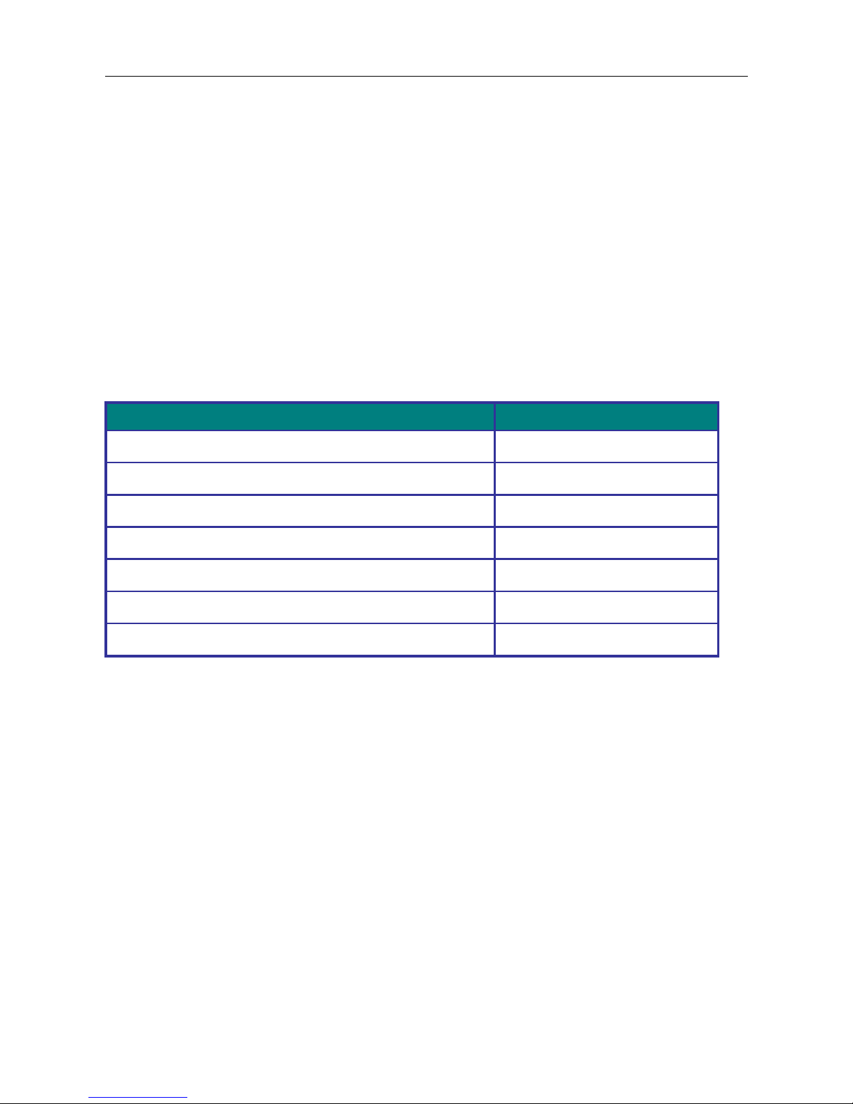
Please verify the box contains the following items:
Item
Quantity
Management Ethernet switch
1
Wall-mount plates
2
DIN-Rail CLIP
1
M3 Screws (for the wall mount plates & DIN CLIP)
4
DC power terminal block
1
RJ45 Ethernet port Dust Cover
Some
SFP Ethernet port Dust cover
Same as SFP port number
Page 2
Quick Installation Guide
2
Safety Instructions
When a fiber connection is removed during installation, testing, servicing or an active fiber is
broken, ocular exposure to optical energy may be potentially hazardous, depending on the
laser output power.
The primary hazards of exposing laser radiation from an optical-fiber communication systems
are:
●
Damage to eyes from accidental exposure to a beam emitted by a laser source.
●
Damage to eyes from viewing the connector that attaches to a broken fiber or an
energized fiber.
Technical Specifications
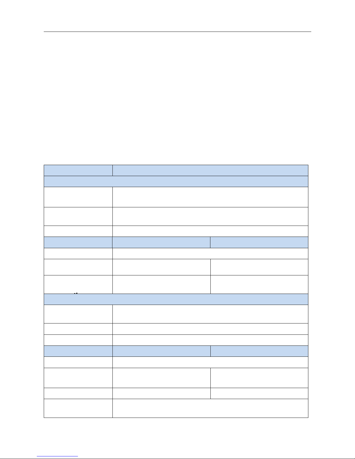
Model
MLB-E42xx & MLB-E42xx-P Series
Ethernet
Copper RJ45 Ports
10/100/1000 Mbps speed auto-negotiation
MDI/MDIX Auto-crossover
SFP (pluggable
Ports)
100/1000Base SFP slot
Fiber port connector
LC typically for fiber (depends on module)
Power
MLB-E42xx series
MLB-E42xx-P series
Power input
Redundant Input Terminals; Reverse power protection
Input voltage range
12-58 VDC
12-58 VDC (with POE: 46-58
VDC)
Maximum
Power
17 Watts
Without PoE: 14 Watts
With PoE: 265 Watts
Environmental and Compliances
Operating
temperatur
-40 to +75°C (cold startup at -40°C)
Storage temperature
-40 to +85°C
Humidity
5 to 95% RH (non-condensing)
Mechanical
MLB-E42xx series
MLB-E42xx-P series
Ingress protection
IP30
Dimension
(without DIN rail clip)
154mm(H) x 109mm(D) x
60mm(W)
154mm(H) x 128mm(D) x
77mm(W)
Weight
1056g
1410g
Installation option
DIN-Rail mounting
Wall mounting
Page 3
Quick Installation Guide
3
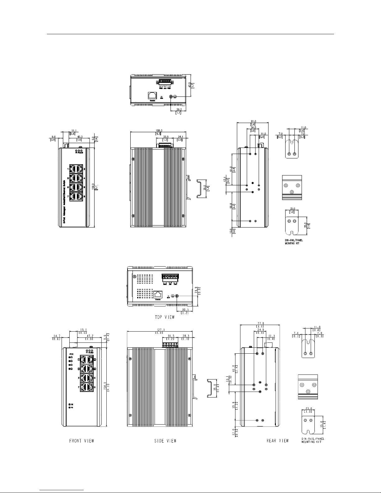
Appearance
MLB-E42xx
MLB-E42xx-P
Page 4
Quick Installation Guide
4
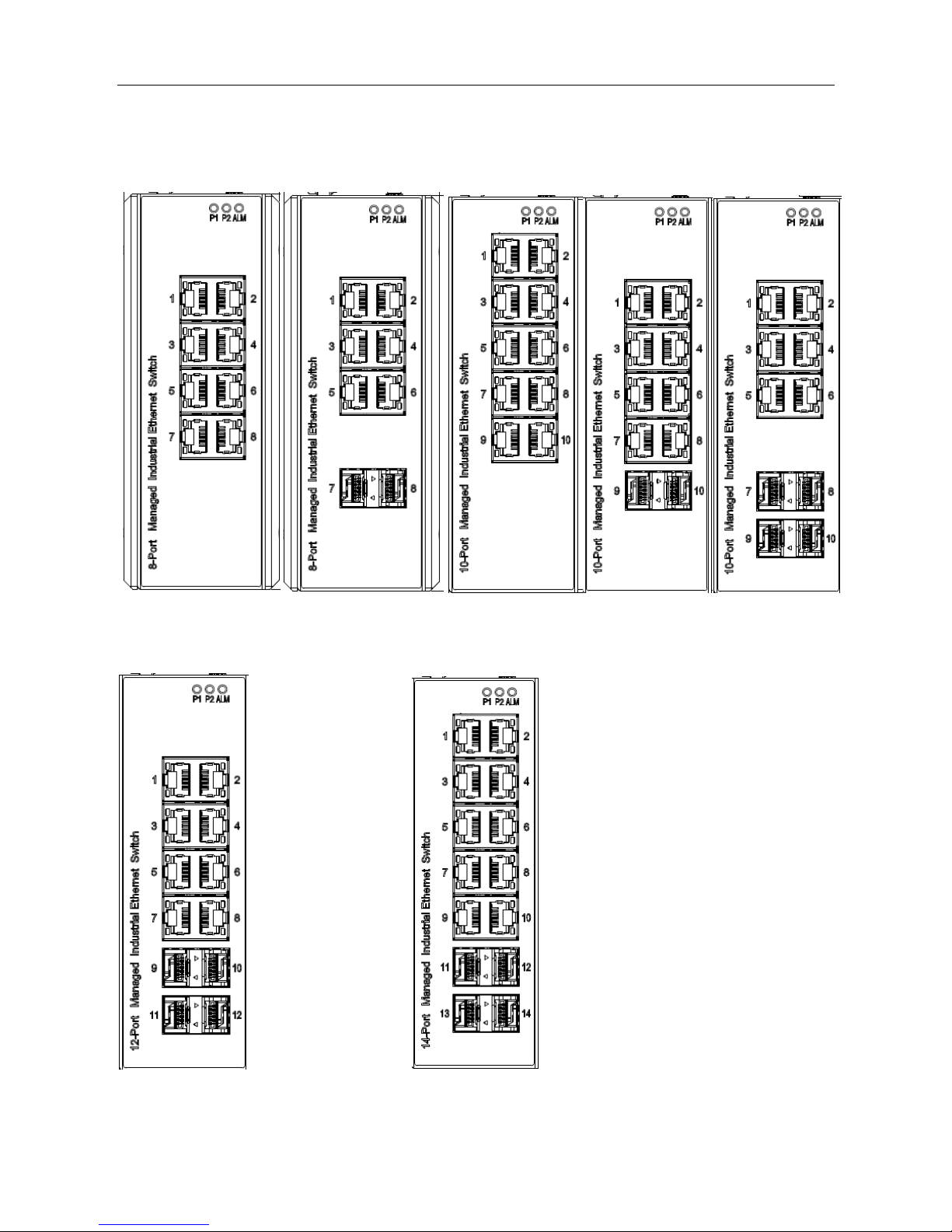
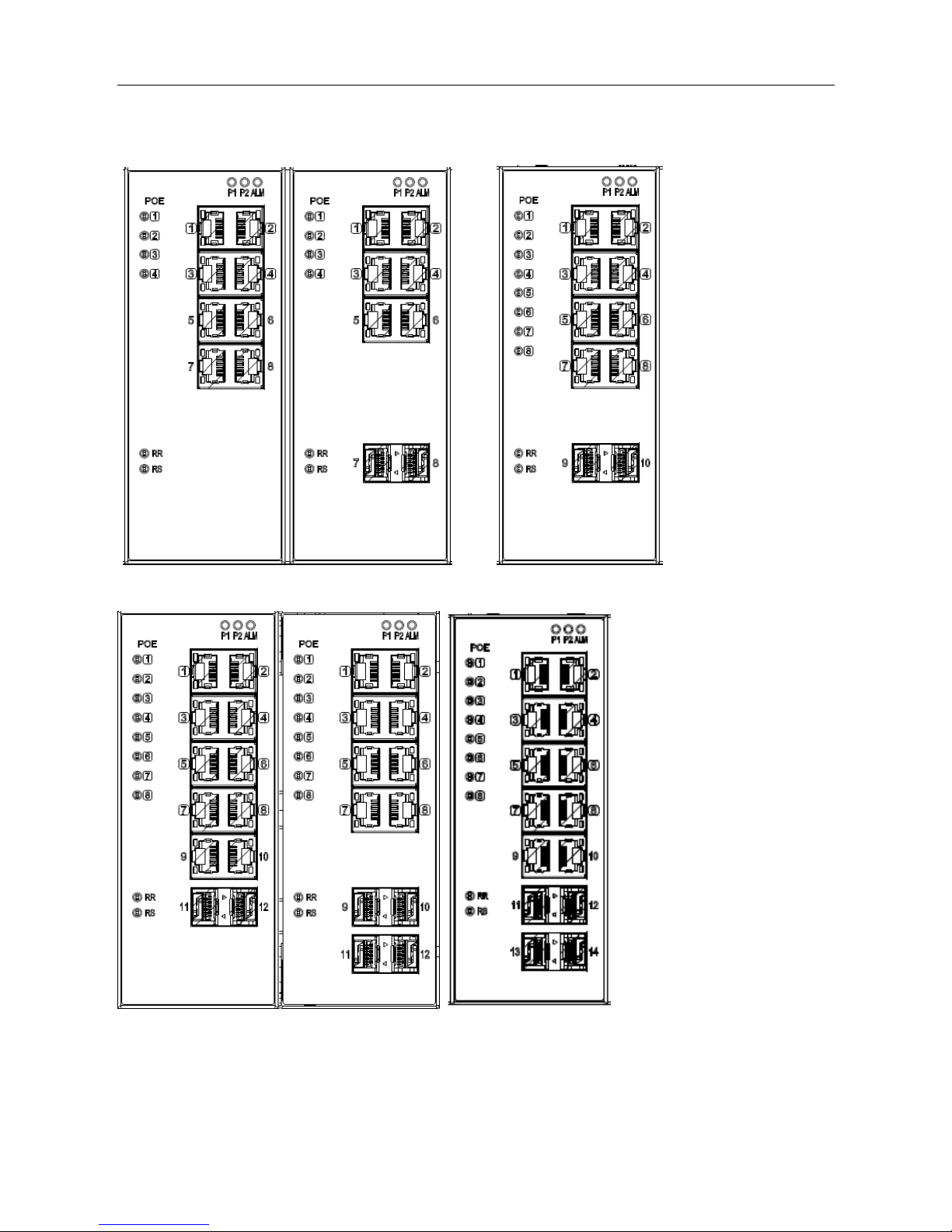
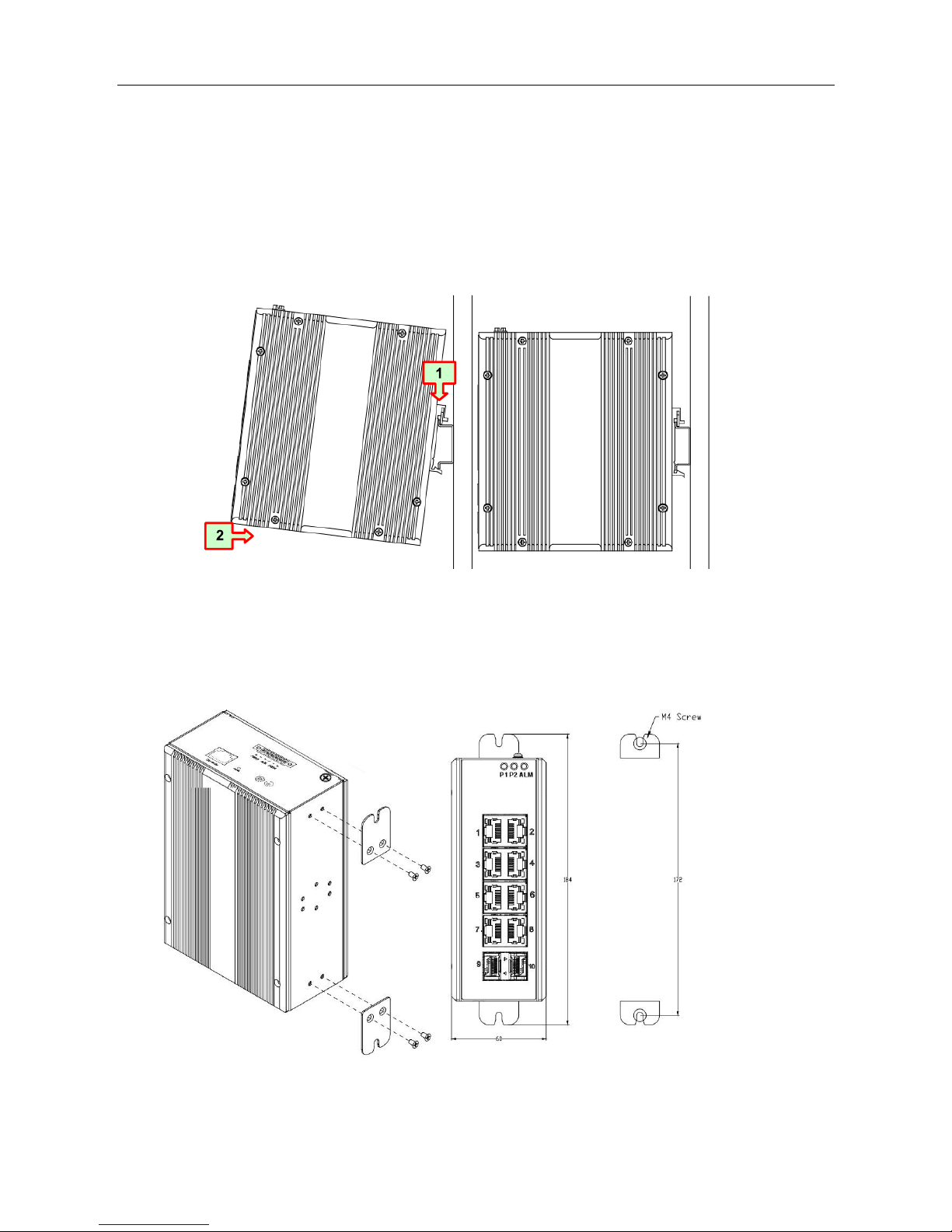
Faceplate
MLB-E42xx
8-Port series 10-Port series
12-Port series 14-Port series
Page 5
Quick Installation Guide
5
MLB-E42xx-P
8-Port series 10-Port series
12-Port series 14-Port series
Page 6
Quick Installation Guide
6
DIN-Rail Mounting
Mounting steps:
1. Screw the din-clip with screws in the accessory kit.
2. Hook the unit onto the din-rail.
3. Push the bottom of the unit towards the din-rail until it locks in place.
Wall Mounting
Mounting steps:
1. Screw the wall-mount brackets with screws in the accessory kit.
The graph is for all series
Page 7

Quick Installation Guide
7
Ethernet Interface (RJ45 Ethernet)
The switch provides two types of Ethernet interfaces: electrical (RJ45) and optical (SFP)
interfaces.
Connecting the Ethernet interface via RJ45:
●
To connect the switch to a PC, use straight-through or cross-over Ethernet cables,
●
To connect the switch to an Ethernet device, use UTP (Unshielded Twisted Pair) or
STP (Shielded Twisted Pair) Ethernet cables.
The pin assignment of RJ-45 connector is shown in the following figure and table.
MLB-E42xx
MLB-E42xx-P
Ethernet Interface (Fiber, SFP)
For both 100/1000 Mbps fiber speed connections, the SFP slots are available. The SFP slot
accepts the fiber transceivers that typically have an LC connector.
The fiber transceivers have options of multimode, single mode, long-haul or specialapplication transceivers.
DANGER: Never attempt to view optical connectors that might be emitting laser energy.
Do not power up the laser product without connecting the laser to the optical
fiber and putting the dust cover in position, as laser outputs will emit
infrared laser light at this point.
Pin
Assignment
PoE
Assignment
1,2
T/Rx+,T/Rx-
Positive V
Port
3,6
T/Rx+,T/Rx-
Negative V
Port
4,5
T/Rx+,T/Rx-
X
7,8
T/Rx+,T/Rx-
X
Pin
Assignment
1,2
T/Rx+,T/Rx-
3,6
T/Rx+,T/Rx-
4,5
T/Rx+,T/Rx-
7,8
T/Rx+,T/Rx-
Page 8
Quick Installation Guide
8
Connecting Power Terminal Block
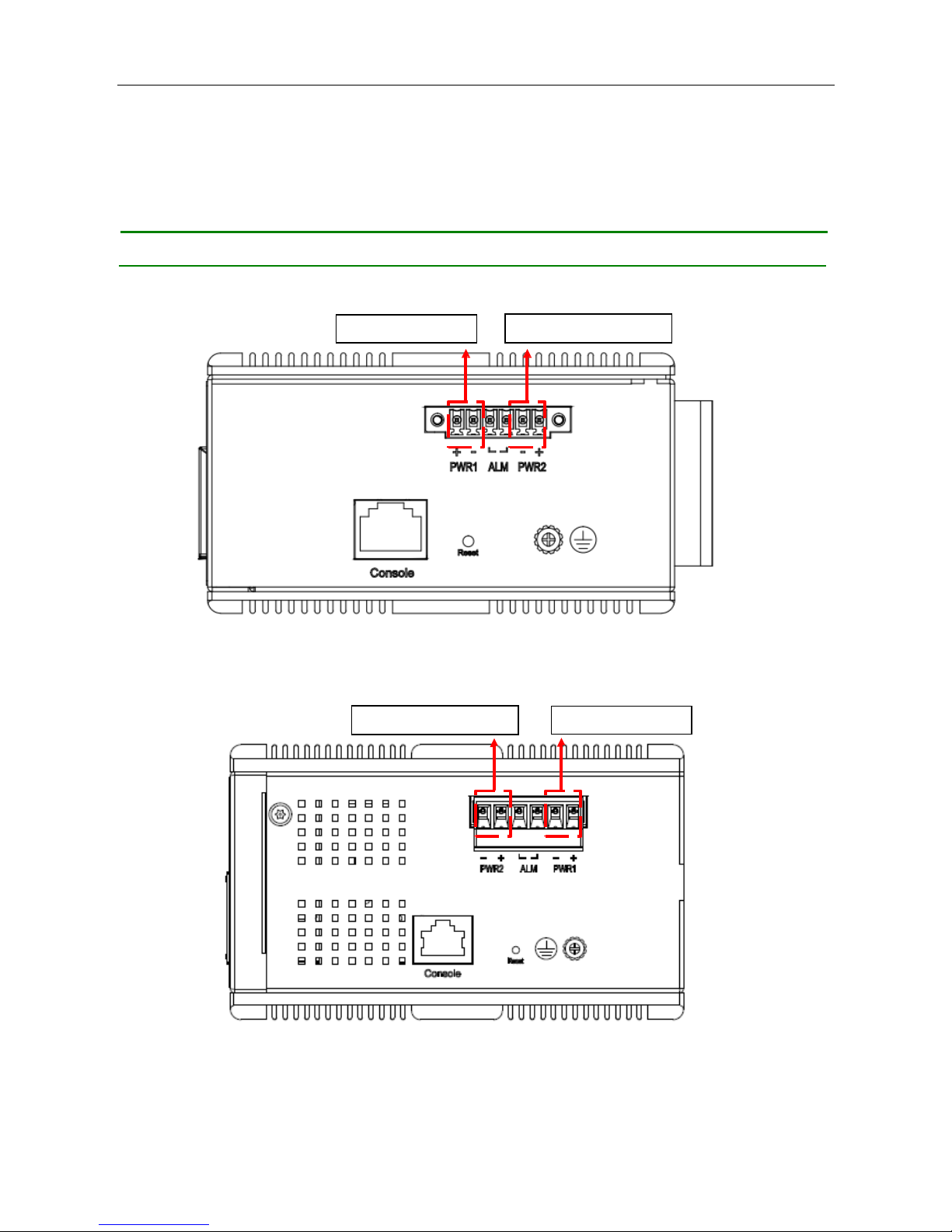
The switch can be powered from two power supplies (input range 12V – 58V). Insert
the positive and negative wires into V+ and V- contacts on the terminal block
respectively and tighten the wire-clamp screws to prevent the wires from being
loosened.
Note: 1. The DC power should be connected to a well-fused power supply.
MLB-E42xx
MLB-E42xx-P
First Power Supply
Second Power Supply
First Power Supply
Second Power Supply
Page 9
Quick Installation Guide
9
Alarm Relay and Ground
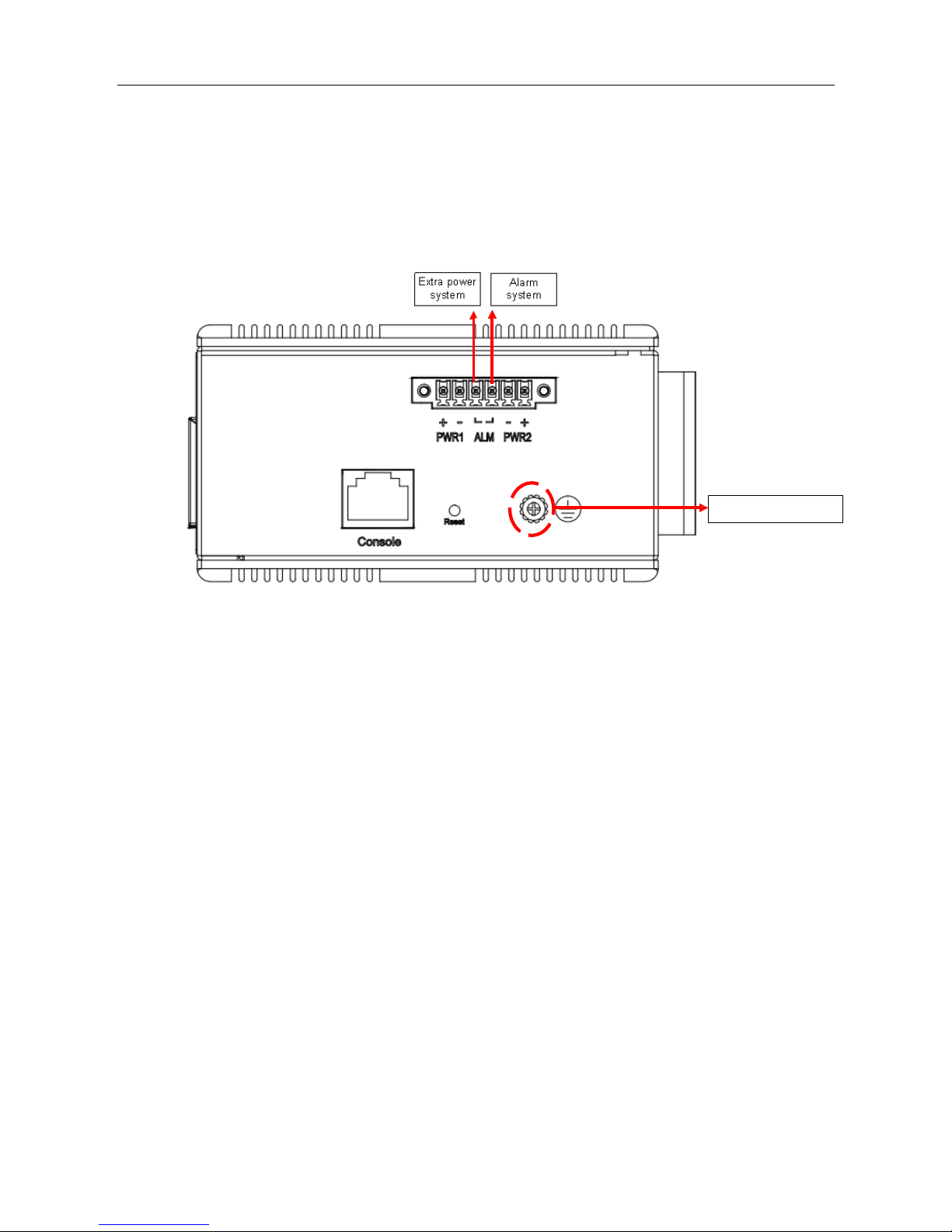
The alarm relay output contacts are in the middle of the DC terminal block connector as
shown in the figure below.
The alarm relay out is “Normal Open”, and it will be closed when detected any predefined
failure such as power failures or Ethernet link failures.
The relay output with current carrying capacity of 0.5A @ 24 VDC
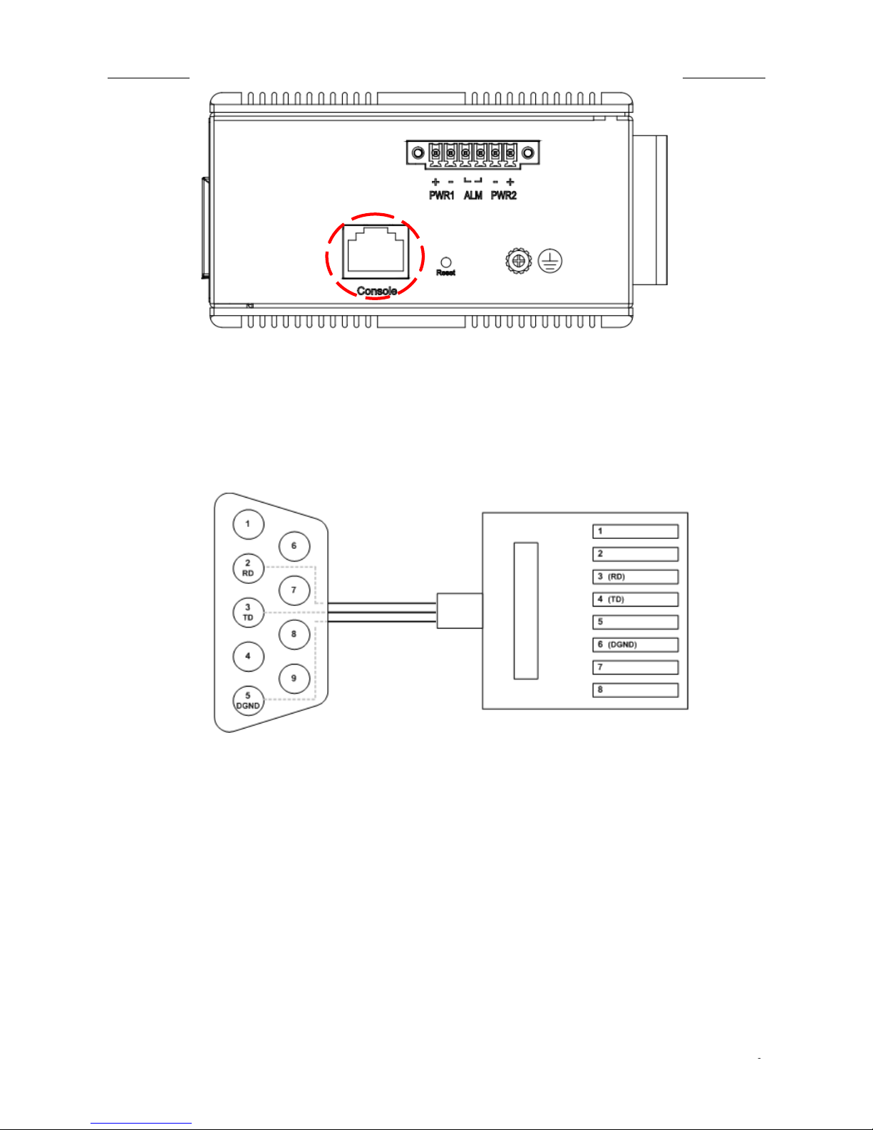
Console Connection
The Console port is for local management by using a terminal emulator or a computer with
terminal emulation software.
●
DB9 connector connect to computer COM port
●
Baud rate: 115200bps
●
8 data bits, 1 stop bit
●
None Priority
●
None flow control
Ground Connector
Page 10
Quick Installation Guide
1
To connect the host PC to the console port, a RJ45 (male) connector-to-RS232 DB9 (female)
connector cable is required. The RJ45 connector of the cable is connected to the CID port of
IVS-500; the DB9 connector of the cable is connected to the PC COM port. The pin
assignment of the console cable is shown below:
Connect & Login to Managed Switch
1. Connecting to the Ethernet port (RJ45 Ethernet port) of Managed Switch.
2. Factory default IP: 192.0.2.1
3. Login with default account and password.
Username: admin
Password: (none)
CLI Initialization & Configuration (Optional)
1. Connecting to the Ethernet port(RJ45 Ethernet port) of Managed Switch
2. Key-in the command under Telnet: telnet 192.0.2.1
Page 11
Quick Installation Guide
1
3. Login with default account and password.
Username: admin
Password: (none)
4. Change the IP with commands listed below:
CLI Command:
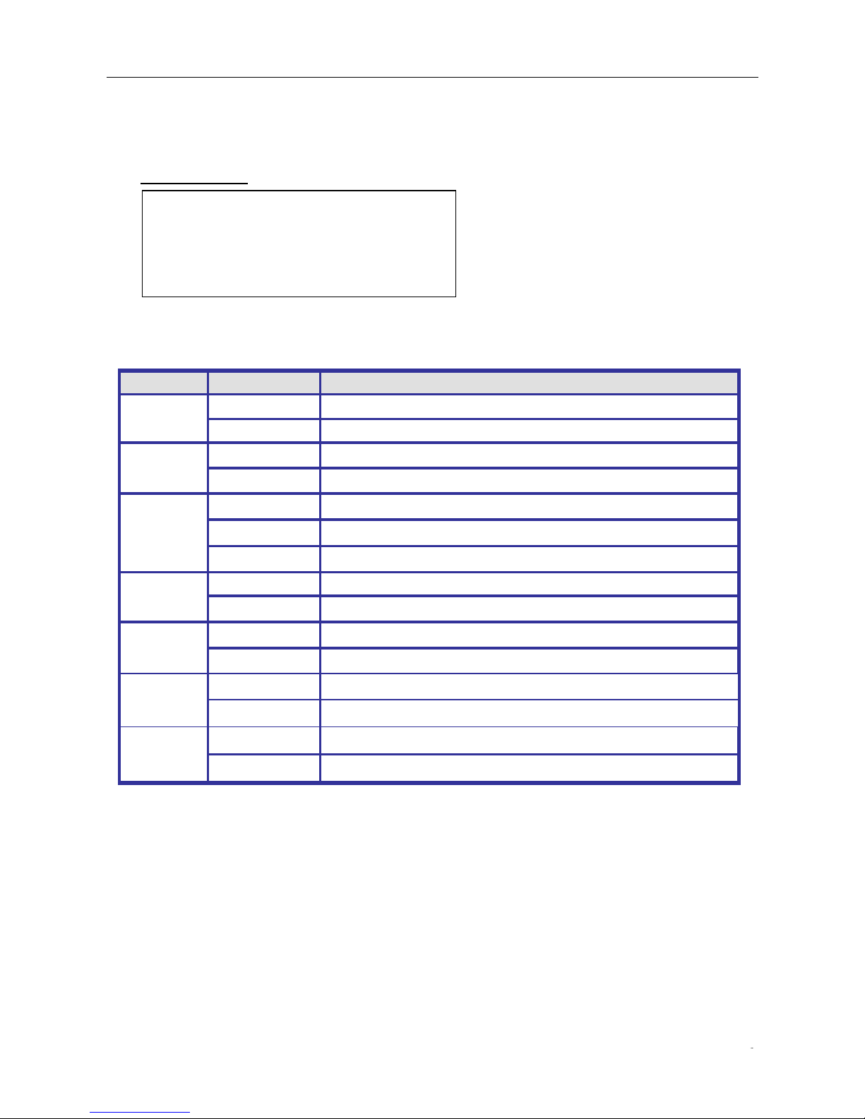
LED STATUS INDICATIONS
LED Name
Indicator /color
Condition
P1/P2
On Green
P1/P2 power line has power
Off
P1/P2 power line disconnect or does not have power supplied
Alarm
On Red
Ethernet link fails, alarm or power failure alarm occurs
Off
No Ethernet link fails and no power failure alarm
Copper port
Link/Act
On Green
Ethernet link up but no traffic is detected
Flashing Green
Ethernet link up and there is traffic detected
Off
Ethernet link down
Copper port
Speed
On Yellow
A 1000Mbps connection is detected
Off
No link, a 10Mbps or 100 Mbps connection is detected
SFP port
Link/Act
On Green
Ethernet link up
Off
Ethernet link down
SFP port
Speed
On Yellow
SFP port speed 1000Mbps connection is detected.
Off
No link or a SFP port speed 100Mbps connection is detected
POE LED
On Yellow
POE is detected
Off
No link
enable
configure terminal
interface vlan 1
ip address xxx.xxx.xxx.xxx xxx.xxx.xxx.xxx
exit
 Loading...