

Page 1

MLCSMLCS
Marvel 60 & 62 Router
instructions
TO AVOID CONFUSION DURING INSTALLATION
follow steps 1 through 5 listed below
Step 1. Remove pages 2 through 6 from book
Step 2. Remove your router install pages
Step 3. Return extra pages to box
Step 4. For smoothest plunging action purchase
STP® before installation. SEE PAGE 3
Step 5. See page 2 for parts diagram
Router Install Pages
MLCS Marvel 60
MLCS Marvel 62
7-8-9
10-11-12
For Parts or Installation Assistance Contact
MLCS Woodworking
1-800-533-9298
mlcswoodworking.com
© 2000-2006 Router Technologies
All Rights Reserved
Page 2
Page 1
METRIC EQUIVILANTS FOR INTERNATIONAL CUSTOMERS
Note: The following metric drill bit or wrench sizes may be substituted
for all operations other than drilling hole for #30 Dust Cover Insert.
1/8” = 0.125" 3.20mm = 0.126"
3/32" = 0.093 2.4mm = 0.094
5/32" = 0.156" no metric equivilant, this hole must be drilled to 5/32"
7/32" = 0.218" 5.5mm = 0.216"
5/16" = 0.312" 8.0mm = 0.315
21/64" = 0.328" 8.3mm = 0.326" or 8.5mm = 0.334"
1/2" = 0.500" 12.8mm = 0.503 or 13mm = 0.511
11/16"= 0.687" 17.5mm = 0.689" or 18mm = 0.708"
3/4" = 0.750" 19.0mm = 0.748
# 30 Dust Cover Insert must be 0.500" use a 12.5mm bit
and sand hole to fit cover. 12.5mm = 0.492"
This instruction manual covers several different makes and models of plunge routers. The instructions are written for
a person with some mechanical ability. If you understand the parts and operation of a plunge router, installing the
Router Raizer is not difficult. Before beginning installation compare the illustrations and photos to your router, original
subbase or router table insert plate. Understand the location and function of both original and Router Raizer parts.
Keep all spare parts, instruction manual and templates for future reference.
Responsibility of the Owner
Important: Read, understand and follow instructions to avoid personal injury.
1. The responsibility of the owner is to follow the instructions, cautions, and warnings bellow and in the instructions
2. Know and understand the location of both original and Router Raizer parts.
3. Follow all the assembly instructions carefully.
4. Correctly adjust the components making sure the plunge action is smooth and plunge lock operates properly.
5. Carefully read and follow all notes, tips, cautions and warnings.
6. Make sure all operators of the Router Raizer know how to correctly use it.
Caution: Before and during installation of Router Raizer make sure power switch is in the off position and tool is
disconnected from power source to avoid accidental starting of the tool which may result in personal injury.
Caution: Always make sure router power switch is in the off position and disconnected from power source
before and during any adjustments to the router or Router Raizer.
Warning: Never remove or reinstall #31 dust cover or make any depth of cut adjustments from either end of
#1 mainshaft until router power switch is off, cutting tool has completely stopped rotating and tool is disconnected
from power source.
Caution: Always secure plunge lock before and during routing operations.
ROUTER TECHNOLOGIES
LIMITED TWO YEAR WARRANTY
Router Technologies warrants the Router Raizer to be free from defects in material and
workmanship for a period of Two ( 2 ) Years from the original date of purchase to original
owner. Our responsibility under this warranty is to replace, at no cost, any part which
upon inspection at our facility is found to be defective in either material or workmanship.
This warranty does not imply that the product is fit for a particular use or application, this
warranty does not apply to parts which have been modified, altered, misused, damaged
by improper storage. It also does not cover loss of parts during use, or mechanical
adjustments which are covered in the instruction manual. In no event shall Router Technologies be liable for any indirect, incidental or consequential damages from the
sale or use of the product. This disclaimer applies both during and after the term of the
warranty.
This warranty is your only remedy and parts are to be returned prepaid to our facility for
inspection at Router Technologies, 2729 Delaware Ave, Des Moines, IA. 50317.
This warranty gives you specific legal rights, and you may have other rights which may
vary from state to state. Any legal actions must be brought in Polk County Iowa.
© 2000-2006 Router Technologies
All Rights Reserved
Page 3
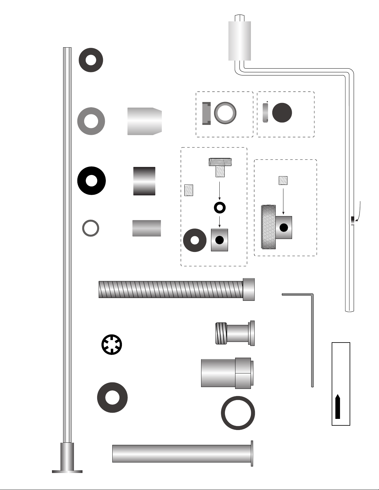
#14 Steel
3/16" Washer
#12 Green
Nylon
Bushing
Parts Shown Full Size
#10 Black
Nylon
Bushing
#30 Dust Cover
Insert
#24 Thumb
Screw
#31 Dust Cover
one extra included
#27 Yellow
Set Screw
( 10 / 32 )
Page 2
Magnet
#9 Red
Nylon
Bushing
MLCS Marvel Parts Diagram
#15 Retainer
three extra
included
#25 Optional Black
Set Screw ( 10 / 32 )
Top
View
Side
View
#23 Rubber
O-ring
Collar
#22 Rapid
#21 Lead Screw
#40 Housing
Bushing
#19 Short
Drive Nut
#26 Top Drive
#29 Speed Wrench
#28 Allen Wrench
Note; Actual mainshaft length 13 1/2"
Caution: Before and during installation of Router Raizer make sure power switch is in the off position and tool is
disconnected from power source to avoid accidental starting of the tool which may result in personal injury.
#1 Mainshaft
#7 Brass
Washer
#18 Drive Nut
Washer
#13 Brass
Spring Guide
#46 Allan Screw Locating Pin
© 2000-2006 Router Technologies
All Rights Reserved
Page 4
READ THIS PAGE BEFORE INSTALLATION
1. Remove Pages From Book
Before installation please remove the pages required for your router from this book.
Failure to due so can result in referring to the wrong page, confusion and damaged parts!
2. Installation
The Router Raizer is designed to make the plunge router easy and enjoyable to adjust . It may appear to be complex and
difficult to install, but the plunge router is an easy tool to disassemble and reassemble. Allow approximately 1 / hours for
installation.
1
2
Page 3
3. Multiple Parts
Thisl kit contains parts for all MLCS Marvel routers. Each instruction page lists the parts required for installation into that router.
We advise keeping and storing all the extra parts and instructions.
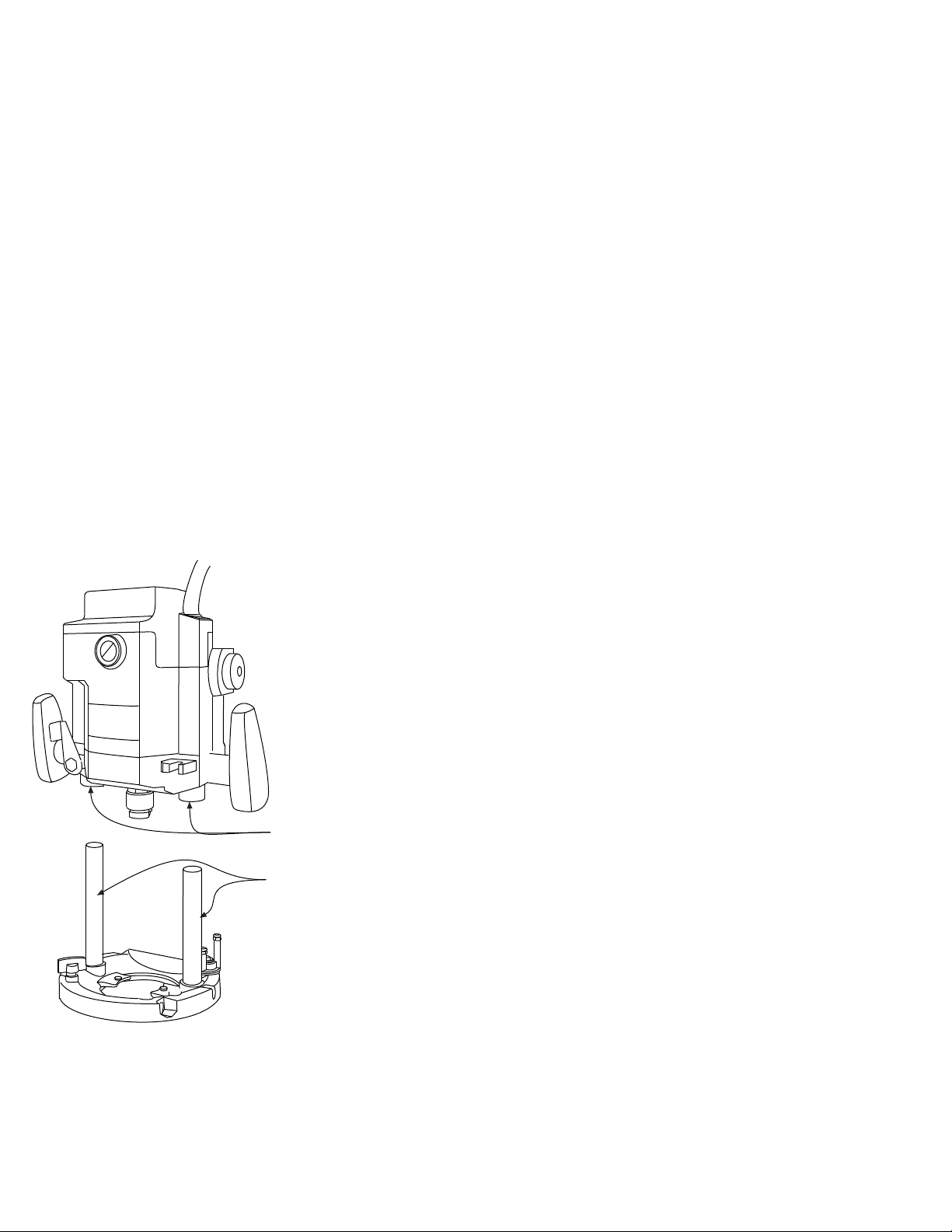
4. STP® for Lubricating The Plunging Action
( After installation you will have extra parts )
( All Plunge Routers )
For maximum performance and smoothest plunging action all plunge posts require
a light film of lubrication. We only recommend using STP® MOTOR OIL TREATMENT.
Before beginning the installation please purchase a bottle of STP®. Apply a light film
to the posts and inside the post bushings just before reassembling the router.
1. Install the Router Raizer components into the base and motor housing of the router.
2. Before reinstalling the motor housing onto the base, use a Q tip, brush or little finger
to apply a film of STP® to the inside of both post bushings and the outside of both
plunge posts.
NOTE: STP® on the posts can attract dust, but the lubricating properties are not affected.
periodically wiping the posts clean and reapplying STP® to the posts only will
keep the router operating smoothly.
Post Bushings
Apply light film on the inside surface of both post bushings.
© 2000-2006 Router Technologies
All Rights Reserved
Plunge Posts
Apply light film to the outside surface of both plunge posts.
Page 5
Page 4
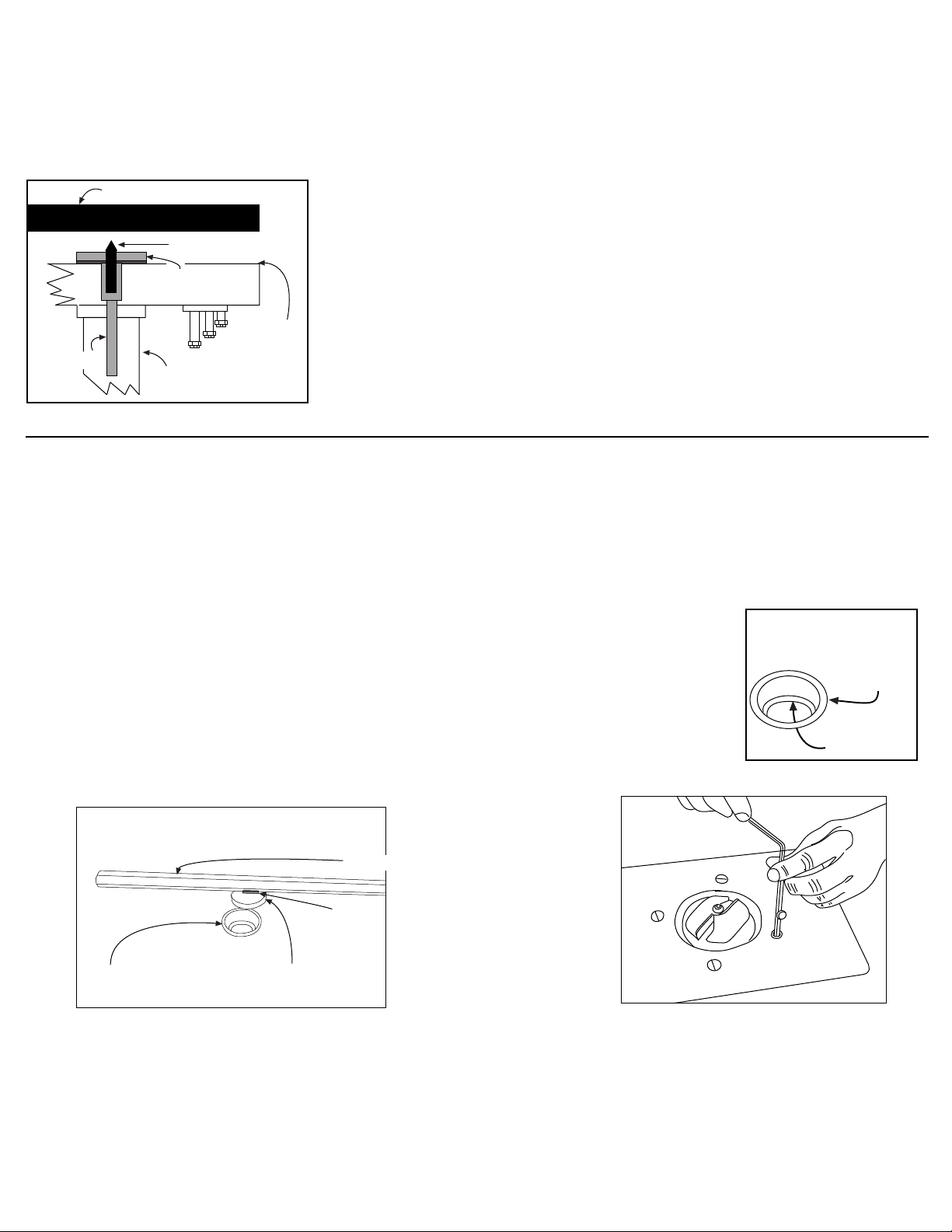
Using the #46 Locating Pin
Use this pin to simplify locating the Router Raizer access hole required through the original subbase or router table.
Original Subbase or Router Table
# 46 Locating Pin
Using fig 1 support router upside down on bench and place locating pin into bottom of #1
mainshaft head. Secure subbase to router base gently tightening screws. Using a hammer
gently tap the subbase over the pin. Remove subbase and drill hole on center punch mark
using the Router Raizer template instructions.
Locating Hole in Router Table
Locating Hole in Original Subbase
1.
#1 Mainshaft
2.
#1 Mainshaft
Head
Plunge
Post
Bottom
Router Base
fig 1
If your router table is already drilled to mount the router, use above step using table or insert
plate in place of original subbase.
If your router table or insert plate have not been drilled use the provided paper template or
original subbase to first locate and drill the router mounting holes, then use #46 locating pin
to drill Router Raizer access hole.
NOTE: For highest accuracy, the locating pins point should just project above the #1 mainshaft
head. Shorten the pin to desired length by securing pointed end of locating pin in jaws of cordless or electric drill. Grind but end of pin off and debur ground end.
Cool pin before removing from chuck jaws!
Preparing and Drilling Router Table Top
NOTE: All installations require a 1/2" diameter hole drilled through the top of your router table top or insert plate to
accept the #30 dust cover insert
Install #30 dust cover insert
Install #30 dust cover insert
Stop Ring Down
Installing #30 Dust Cover Insert and #31 Dust Cover
1. Using ( fig 1 ) select #30 dust cover insert ( 1/2" dia, X 3/16" tall, turned aluminum ring ) and #31 dust cover
( 3/8" dia. X 1/8 thick stamped steel plug ) From top of insert plate, press #30 cover insert into the
1/2" Router Raizer access hole until flush.
Tip: If cover insert fits loosely, secure with drop of Super Glue® or Krazy Glue®.
2. Mount router to insert plate and install into table
3. Place #31 dust cover into #30 dust cover insert. Using ( fig’s 1 & 2 ) remove #30 dust cover with magnet on
back of #29 speed wrench. With dust cover on speed wrench, insert wrench to make adjustments. To reinstall
dust cover, place cover into insert and slide wrench away. Caution: Remove dust cover with speed wrench
before removing router from table or cleaning table with vacuum sweeper.
Stop Ring Down
Top
#30 dust cover
insert
Stop Ring
fig 1
#30 Dust Cover Insert
Insert Plate
#29 Speed Wrench
Magnet
#31 Dust Cover
© 2000-2006 Router Technologies
All Rights Reserved
fig 2
Page 6
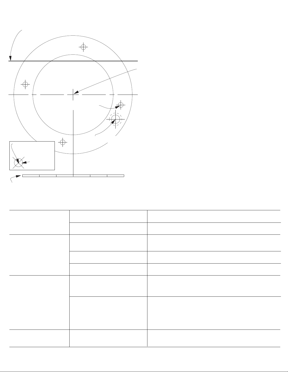
Using Paper Drilling Template
Page 5
Router table fence reference line
Refer to pages 4,5,6 before using template
Additional Templates Available on Website
Router mounting holes
Router Raizer Access Hole
1/2" = .500
.500" reference circle
for drilling table top or
insert plate.
Use this 6" scale to check accuracy when copied
1. Place paper template lettering up onto top side of router table or inset plate.
2. Router table fence reference line. Setting this line parallel with the back
edge of the router table or insert plate positions the router so the
Router Raizer access hole will be drilled out in front of the fence.
Router Raizer access hole
Drill .500" hole
through router
table insert plate
install #30 dust cover insert
into .500" hole and press flush
with top of insert plate
NOTE: This hole must be drilled 1/2" or .500"
for #30 dust cover insert to fit properly.
3. Center cross hairs. Accurately center this point in the hole of the
router table or insert plate, using a pencil compass or tape measure.
Tape in place and recheck before drilling holes.
4. Router mounting holes. For highest accuracy place the routers
original subbase over the templates router mounting holes and
tape subbase down. Use a Vix bit, center punch or drill bit to
transfer holes to the router table or insert.
5. Router Raizer access hole. Use page 4 and # 46 locating pin to
accurately mark the access hole location
WARNING: A 1/2" HOLE IS REQUIRED IN THE TABLE TOP TO
ACCEPT THE #30 DUST COVER INSERT.
IF ORIGINAL SUBBASE IS USED BETWEEN ROUTER AND
TABLE TOP USE #46 LOCATING PIN THEN DRILL 3/8" HOLE
THROUGH ORIGINAL SUBBASE.
6" Scale. If template is copied or downloaded from web site, use this
scale to accurately check template size.
Troubleshooting
Problem Cause Solution
Router Raizer will not
raise or lower the router
Router Raizer Speed Wrench
turns hard
Router Raizer will not
raise router high enough
#19 or #20 Drive nut loose
Router plunge posts dry
#21 lead screw has no lubrication
Router plunge posts dry
Turret stop on router improperly set
Reached maximum
plunge depth of router
The drive nut cannot rotate, Retighten the drive nut on router.
Clean posts and lubricate with STP® MOTOR OIL TREATMENT
Re lubricate using supplied red grease or heavy wheel bearing grease.
Clean posts and lubricate with STP® MOTOR OIL TREATMENT
Locate rotating turret stop on base of router and adjustable stop
directly above. Adjustable stop must be retracted as high as possible.
Turret stop must be rotated so shortest post is under adjustable stop.
All plunge routers have a predetermined plunge stroke, the RouterRaizer will not increase this stroke. With router fully compressedcheck amount of plunge post still visible. 1/16" to 1/4" post should
be visible.
If more than 1/16" to 1/4" of post is visible, Call 1-866-266-1293
Addition of a collet extension is required to safely run some bits.
Router becomes harder
to raise and lower
Router plunge posts dry
Clean posts and lubricate with STP® MOTOR OIL TREATMENT
© 2000-2006 Router Technologies
All Rights Reserved
Page 7
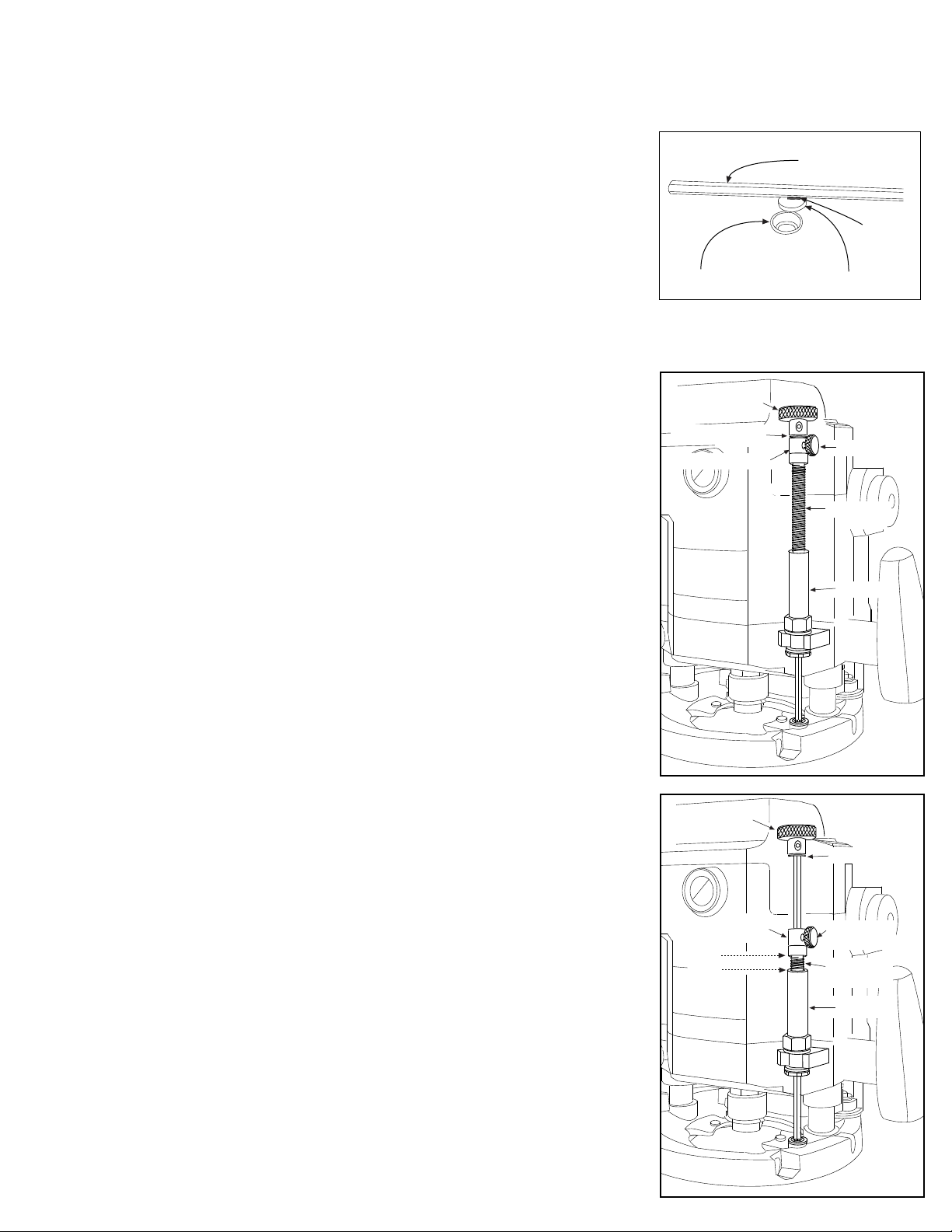
Page 6
Router Raizer Use Instructions
Caution: Always make sure router switch is in the off position, and tool is disconnected from power source when performing maintenance
or making any adjustments to either the router or height adjustments to avoid accidental starting of tool which may result in personal injury.
Using in a Router Table
fig 1
Insert Plate
#29 Speed Wrench
Dust Cover Insert and Dust Cover
The dust cover insert and dust cover allow easy adjustment access to the Router Raizer mainshaft
and restricts dust and debris infiltration during use. A small magnet is recessed into speed wrench
handle to remove and hold the dust cover during adjustments.
1. Removing dust cover: Using ( fig 1 ) place #29 speed wrench over #31 dust cover, lift speed-
wrench to remove dust cover. Leave dust cover on wrench while making height adjustments.
2. Replacing dust cover: Position speed wrench with dust cover over the insert, press cover
into insert and swipe wrench away leaving the dust cover in the insert.
#30 Dust Cover Insert
3. Always remove #31 dust cover before removing router and insert from table. Or cleaning table with vacuum sweeper
Warning: Never remove the dust cover while the router is running. Allways wait until the bit has stopped spinning.
4. Rapid collar positioning: The rapid collar is for hand held use only, for router table use
position collar against retainer clips and top drive ( fig 2 ). Secure with #24 thumb screw or
optional #25 black set screw.
Using Handheld
When used hand-held the hex shaped #1 mainshaft provides a constant engagement of the
Router Raizer mechanism, allowing easy height adjustments while retaining original plunge
capabilities and all other original functions of the router.
#26 Top Drive
#15 Retainers
#22 Rapid Collar
1. Height adjustments can be made from either end of the router. To adjust from the base, engage
#29 speed wrench into the head of #1 mainshaft. To adjust from the top, engage #29 speed
wrench into the top of #26 top drive. The knurled #26 top drive also allows adjustments by hand.
The #24 thumb screw and #22 rapid collar allow positioning the cutter to height. bypassing
multiple revolutions of the speed wrench
1. ( fig 2 ) Illustrates compressing the plunge router with rapid collar locked in the router table
position. Insert #29 speed wrench into #26 top drive, or lay router on its side and insert #29
speed wrench into bottom of #1 mainshaft. Rotating the speed wrench will thread #21 lead screw
in or out of the drive nut, compressing and un compressing the router.
2. ( fig 3 ) Illustrates compressing the plunge router with the rapid collar. Thread #21 lead screw into
the drive nut leaving approx 1/2" exposed threads, the router will be un compressed. Secure
desired router bit in collet, stand router upright hand plunge to approx desired depth lock plunge
lock lever. Release #24 thumb screw and drop rapid collar into contact with #21 lead screw.
secure thumb screw and release plunge lock lever. Insert #29 speed wrench into #26 top drive,
or lay router on its side and insert #29 speed wrench into bottom of #1 mainshaft and adjust to
required depth. Re lock plunge lock before routing. When done release thumb screw and router
will quickly return to the un compressed position for easier bit removal.
Caution: #22 rapid collar is not designed to maintain cutter height during routing operations.
Always secure plunge lock before and during all routing operations.
#26 Top Drive
Magnet
#31 Dust Cover
fig 2
#24 Thumb
Screw
#21 Lead
Screw
Drive Nut
fig 3
4. If #24 thumb screw will not provide enough pressure to secure #22 rapid collar, replace thumb
screw with #25 optional black set screw and #28 allen wrench.
Direction of Rotation for Adjustment
Adjustments from #26 top drive:
Clockwise rotation Decreases depth of cut. Counterclockwise rotation Increases depth of cut.
Adjustments from #1 Mainshaft Head :
Clockwise rotation Increases depth of cut. Counterclockwise rotation Decreases depth of cut.
One complete rotation of the speedwrench, raises or lowers the bit 1/16"
Caution: Always secure plunge lock during routing operations.
Transporting or Storing Router
To prevent damage to the #1 mainshaft and #21 lead screw, adjust the lead screw
leaving 1/2" threads exposed. Grasp router handles, release plunge lock, advance router up until
lead screw rapid collar and retainers are all in contact, engage plunge lock.
© 2000-2006 Router Technologies
All Rights Reserved
#22 Rapid
Collar
1/2"
#15 Retainers
#24 Thumb
Screw
#21 Lead
Screw
Drive Nut
Page 8
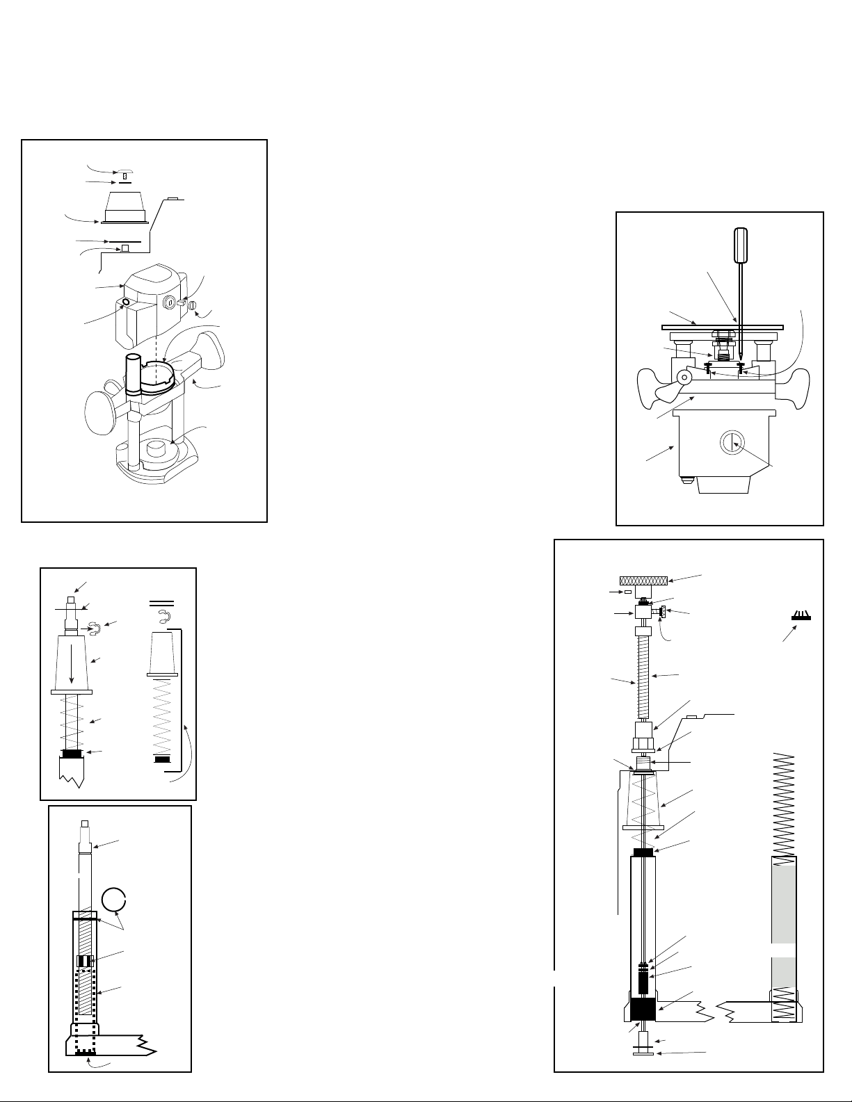
NOTE: Check Off Each Step When Done
MLCS Marvel 60
TOOLS REQUIRED: Phillips screwdriver, straight screwdriver, hammer, 12.8mm or 1/2" and 8mm drill bits.
ROUTER RAIZER PARTS REQUIRED: #1, #7, #9, #10, #12, ( #13 for insallation tool only,) #14, ( three of #15 ) #18, #19, #21, #22,
#23, #24, #26, #27, #28, #29, #40
Note: before installation refer to page 26 lead screw update, check parts.
NOTE: Cut #1 mainshaft to 13" overall length and lightly debur cut end.
screw
steel
washer
height knob
plastic
washer
height
shaft
motor
housing
drill height shaft
hole to 1/2’
height shaft
plastic
washer
height knob assembly
fig 3
C clip
black
spring
cover
spring
spring
bushing
set aside
to reinstall
fig 4
height shaft
internal
C clip
internal nut
plastic
spacer
(shown
dotted lines)
pressed plug
fig 1
brush
brush
cover
fan
shroud
plunge
lock
lever
dust
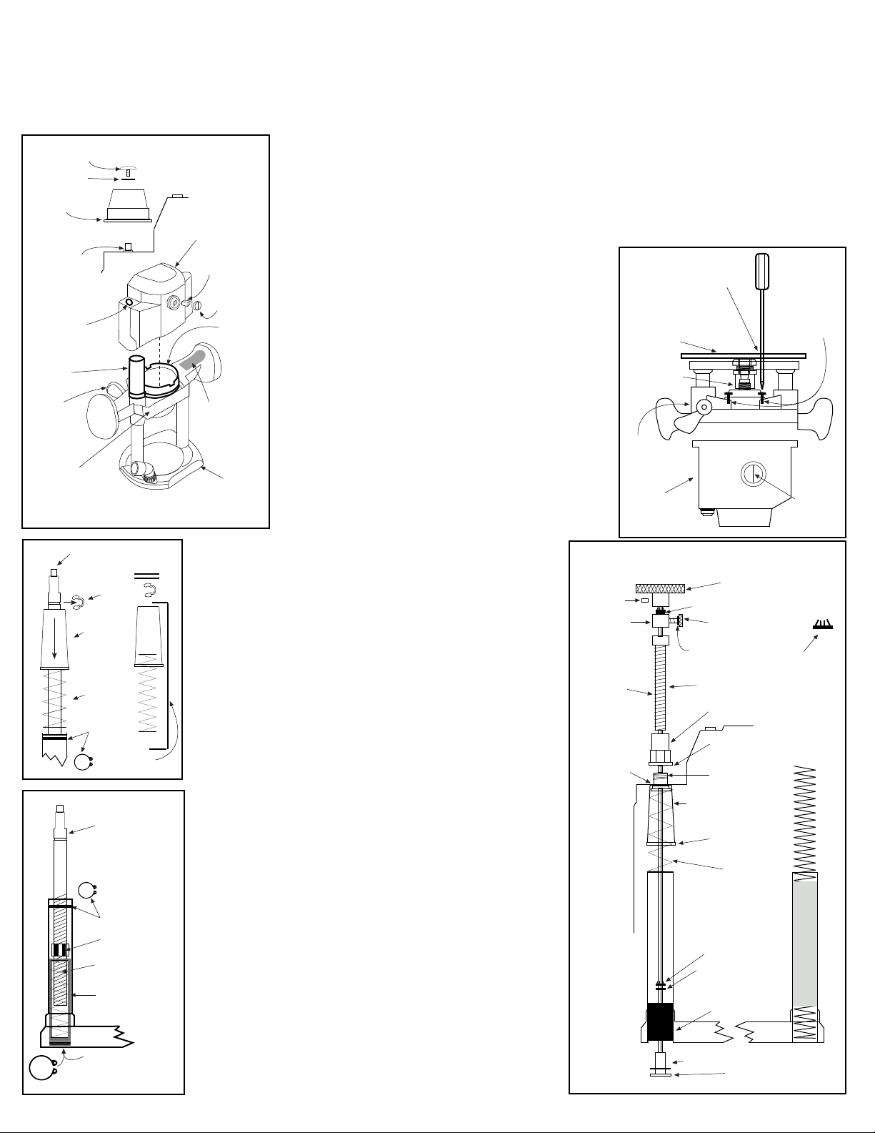
4. Using ( fig 3 ) Remove black spring cover and top spring
shroud
from the bottom housing. Select 1/2" drill bit and drill.
Using fig’s ( 1 & 5 ) Enlarge height shaft hole in top motor
housing and hole in the black spring cover both to 1/2".
Select #19 short drive nut #18 drive nut washer #40
housing bushing. Using fig ( 5 ) The black spring cover
will be secured to the inside of top housing with #40, #18
and #19. Drop #40 housing bushing, threads up onto #1
mainshaft. Using mainshaft as installation tool only, feed
small end of mainshaft into bottom of black spring cover
up through enlarged 1/2" hole. Feed mainshaft up through
1/2" hole in top motor housing, pull mainshaft until threads
on #40 housing bushing are exposed above the top
housing. Drop the #18 washer, then #19 drive nut onto the
mainshaft. Thread #19 onto #40 housing bushing. Tighten
#19 onto #40 using 11/16 wrench (fig 5).
Tip: If nut will not tighten insert flat blade screwdriver into
black spring bushing, wedge #40 while tightening the nut.
Remove mainshaft.
5. Select #10 black nylon bushing, turn bottom housing
upside down, Place plunge post upside down onto block
of scrap wood. Drive #10 black bushing into post until
flush with bottom of post (fig 5). NOTE: the black bushing
will drive in hard, sanding slight bevel on edge will
aid in installing. Do not reduce size of bushing, it must
be tight in the post. Use #12 GREEN bushing to drive
the black bushing in flush with bottom of the post.
Drill the hole in the black bushing with 8 mm drill bit.
#1 mainshaft must spin free when placed into black
bushing. Select #1 mainshaft #7 brass washer #9 red
bushing #14 3/16 steel washer, one #15 retainer clip
#13 hollow spring guide.
6. Place small amount of included red grease onto both sides
of #7 brass washer ,place washer down #1 mainshaft.
Slide mainshaft through #10 black bushing until flush with
base. Stand base upright place #9 red bushing first,
followed by #14 3/16 steel washer onto #1 mainshaft drop
both into the post. Select #13 hollow spring bushing, place
#15 retainer clip teeth up onto the top of the mainshaft.
Using #13 hollow guide flange up, advance #15 clip down
shaft. Place screwdriver or #29 wrench on flange of #13
guide, advance #15 clip into post until tight. #1 Mainshaft
should be secure in the base if you can move it back and
forth, retighten #15 retainer clip Remove and store #13 guide.
7. Place original black spring bushing into topof post, place
spring on top of bushing and plastic spring cover over
spring. Reassemble housings, aligning mainshaft through
the housing bushing. Secure housings with four housing
screws.
1. Remove height knob assembly ( fig 1). Remove both brush covers ( fig 1 )
remove brushes one at a time, labeling the top and side of router removed from on each brush.
2. Remove four screws securing lower motor housing
( fig 2). Secure the power switch in the on position by
wrapping it with tape or a plastic tie strap, to hold it in
position when the router is separated. Separate the
upper and lower case halves by pulling them apart.
No loose parts will fall out., the armature will remain in
the bottom housing.
3. Remove subbase ( fig 2). Stand bottom housing
upright, Using ( fig 3 ) press down black spring cover
and remove C clip. Remove black spring cover, spring,
and spring bushing. Using a small screwdriver remove
fig 2
phillips screwdriver
through base holes
subbase
four housing
screws
internal C clip ( fig 4 ) NOTE: unthreading height
shaft from internal nut improves C clip removal.
Remove internal nut. The pressed plug and plastic
armature
spacer in bottom of post must be removed. Place
height rod into post, tap with hammer to remove plug.
Store plug, plastic spacer, internal nut & height rod,
internal C clip, external C clip washers & height knob.
bottom
housing
top housing
fig 5
#26 top drive
two #15 retainer clips
#24 thumb screw
#23 O ring
#21 lead screw
#19 short drive nut
#18 drive nut washer
(.fits drive nut shoulder)
#40 housing
bushing
black spring cover
spring bushing
#15 retainer clip
#14- 3/16 steel washer
#9 red bushing
black bushing
#7 brass washer (Grease)
#15 retainer clip
teeth up
spring
original
#1 mainshaft
See other side to finish installation.
© 2000-2006 Router Technologies
All Rights Reserved
#27 yellow
set screw
#22 rapid
collar
Grease Lead
Screw Threads
drill hole
to 1/2”
#10
black bushing
drill to 21/64
Page 7
motor
brushes
Page 9
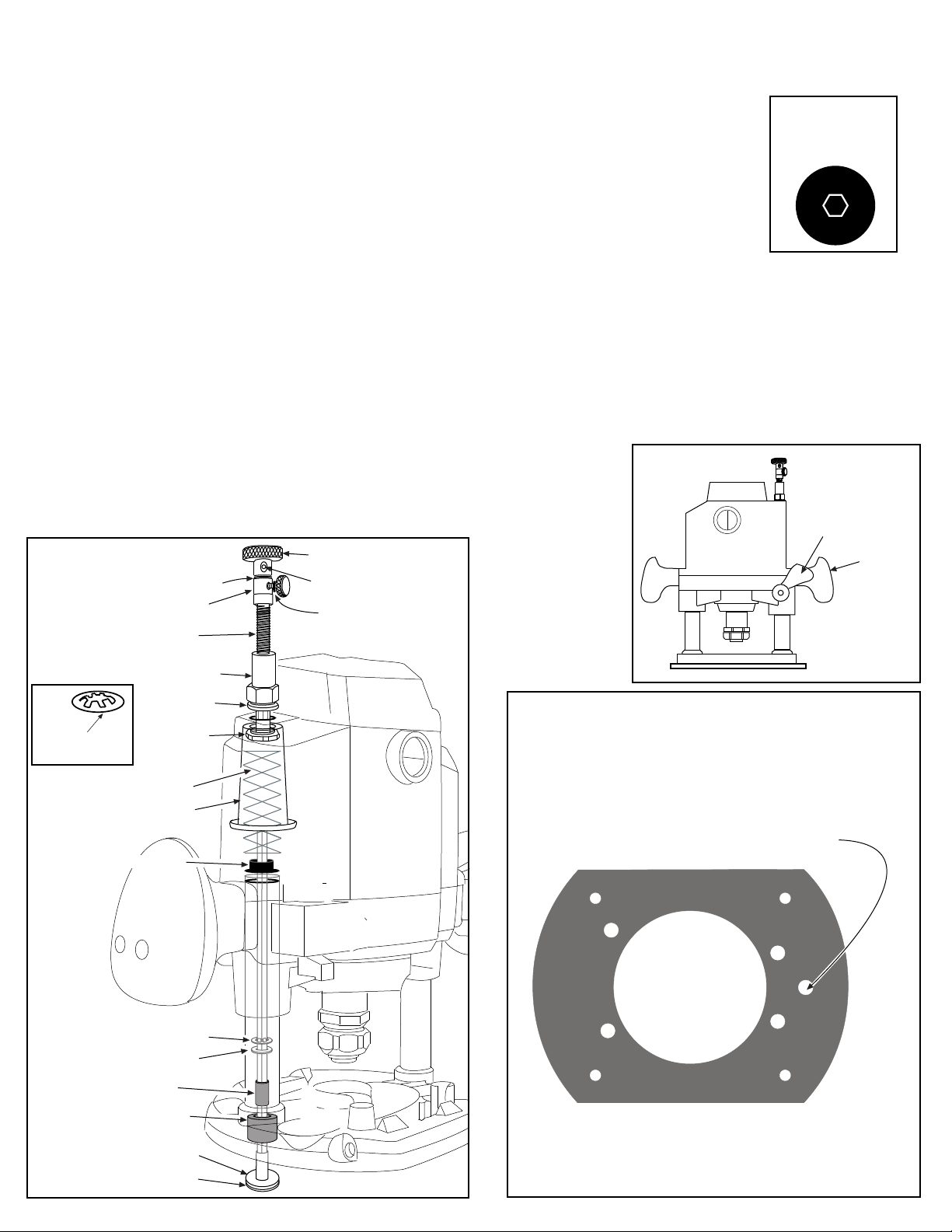
Page 8 MLCS Marvel 60
8. Select #12 green bushing ( Two #15 retainers ) #21 lead screw, #22 rapid collar, #23 O-ring, #24 thumb screw,
#26 top drive, #27 yellow set screw, #28 Allen wrench, red grease. Using ( fig 6 ) place grease on threads of
#21 lead screw, Place lead screw down #1 mainshaft and thread into #19 short nut until one inch of mainshaft
extends above the head #21 lead screw. Alignment of #1mainshaft and #21 screw hex is required ( fig 7 ).
Tip: # 29 speed wrench can be used to speed threading.
fig 7
Top veiw of #21 lead
screw and #1 mainshaft through center.
9. Press #23 O-ring onto #24 thumb screw shaft. Thread thumb screw into #22 rapid collar. Place rapid collar onto
#1 mainshaft 1/2" from top of mainshaft to top of rapid collar and tighten ( fig 6 ). Release plunge lock and slowly
raise the router until lead screw contacts the rapid collar. If the collar moves, reset to 1/2". Place one #15 retainer
teeth up on top of #1 mainshaft, using #12 green bushing as installation tool press retainer into contact with
collar,repeat with second #15 retainer and press flush with first retainer. Return # 12 green bushing to box.
Place #26 top drive onto #1 mainshaft until it contacts retainer clip, Thread #27 yellow set screw into #26 top drive
using #28 allen wrench and tighten. Reinstall motor brushes
10. To ease router raizer adjustments, using fig ( 8 ) slide the small tail of the plunge lock lever spring off the aluminum boss, allowing the
handle to remain in the unlocked position.
Sub-base Plate or Router Table Insert Plate Installation
1. Use #46 locating pin to locate the Router Raizer access hole on the original subbase or router table. For detailed instructions see page 4.
2. See pages 4-5-6 for further instruction, #30 dust cover insert and #31 dust cover, are router table only. Drill a 1/2" hole through insert plate at
the Raizer access point and press #30 in from top until flush. # 31 sets in #30 and is removed during adjustments with magnet on back edge
of #29 speed handle. These components keep dust from entering the Router Raizer hex drive.
3. Periodic inspection and re-greasing of #21 lead screw is recommended.
fig 6
two #15 retainer clips
#22 rapid collar
#21 lead screw
#26 top drive
#27 yellow set screw
#23 O ring
fig 8
Black Plastic
Plunge Lock
Lever
Handle
#19 short drive nut
#18 drive nut
washer
#15 retainer clip
install teeth up
Original Top Spring
black spring cover
original spring bushing
#14- 3/16 steel washer
#9 red bushing
#10 black bushing
drill to 21/64
#40 housing
bushing
#15 retainer clip
fig 9
Locate raizer access point on original subbase.
Drill a 3/4" hole through subbase
Access hole Drill 3/4"
#7 brass washer
#1 mainshaft
© 2000-2006 Router Technologies
All Rights Reserved
Page 10
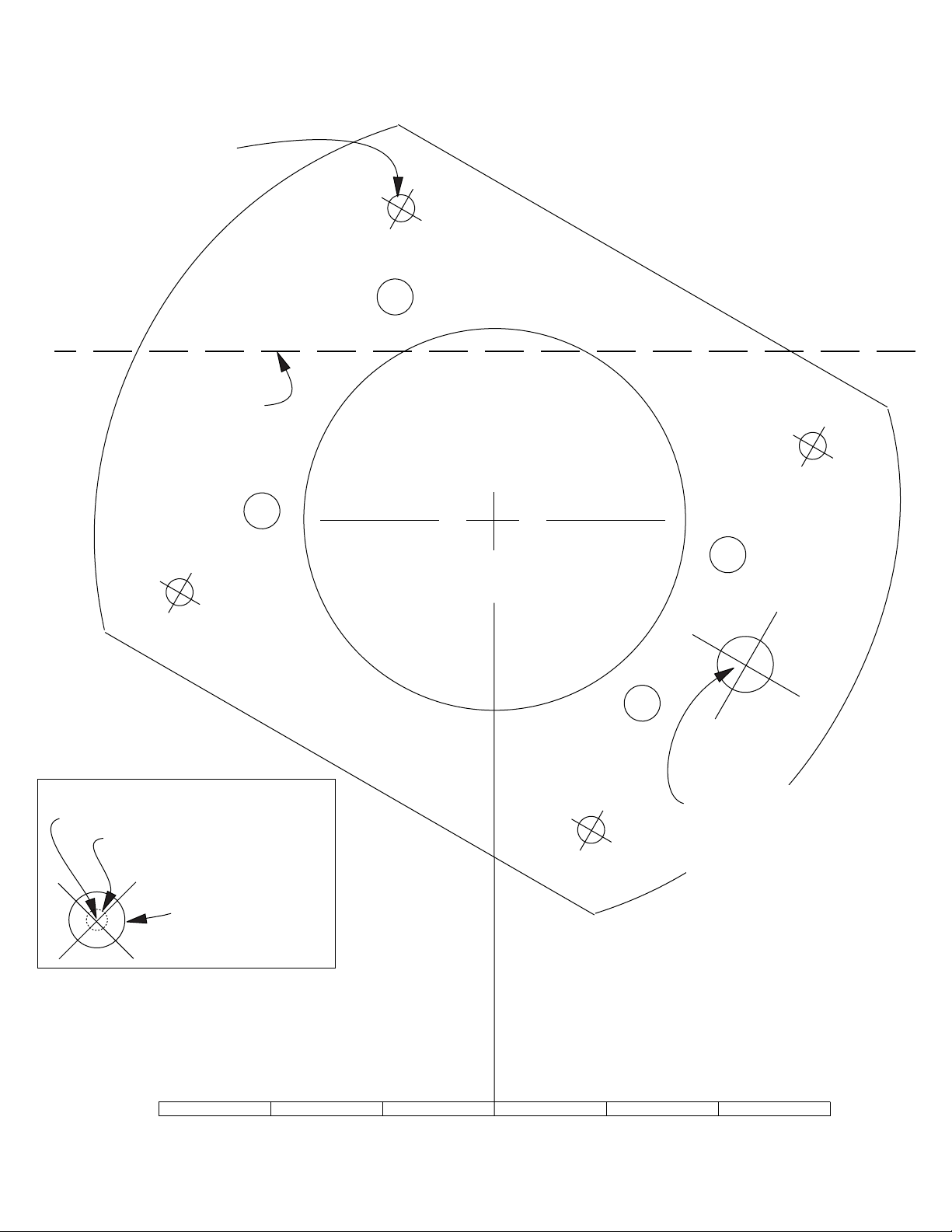
Refer to pages 4-5-6 before using template
Additional Templates Available on Website
Sub-base mounting holes
Router table fence reference line
Page 9
Router Raizer Access Point
5/16" reference circle for drilling
subbase.
1/2" = .500
.500" reference circle
for drilling table top or
insert plate.
Use this 6" scale to check accuracy when copied
Note: Cross lines for locating and drilling holes are accurate. The illustration of subbase may vary
slightly in size and design, but is accurate enough for cutting the rubber gasket if required.
© 2000-2006 Router Technologies
All Rights Reserved
Router Raizer Access Point
Drill .500" hole
through router
table insert plate
install #30 dust cover insert
into .500" hole and press flush
with top of insert plate
NOTE: This hole must be drilled 1/2" or .500"
for #30 dust cover insert to fit properly.
MLCS Marvel 60
Page 11
NOTE: Check Off Each Step When Done
MLCS Marvel 62
TOOLS REQUIRED: Phillips screwdriver, straight screwdriver, hammer, 1/2" and 5/16" drill bits.
ROUTER RAIZER PARTS REQUIRED: #1, #7, #10, #12, ( #13 for installation tool only,) #14, ( three of #15 ) #18, #19, #21, #22,
#23, #24, #26, #27, #28, #29, #40
1. Use mainshaft full length. DO NOT SHORTEN FOR THIS ROUTER
screw
steel
washer
height knob
height
shaft
drill height shaft
hole to 1/2’
black
spring
cover
plunge
lock
lever
BOTTOM
motor
housing
height shaft
C clip
black
spring
cover
top
spring
internal
C clip
height shaft
internal nut
Bottom
internal spring
plastic
spacer
(shown grey)
height knob assembly
fig 3
set aside
to reinstall
fig 4
TOP
internal
C clip
fig 1
TOP
motor
housing
wrap power
switch with
tape
3. Locate the stepped turret stop on the base of the router. Directly above is the adjustable stop
bar, unlock the bar so it moves up and down freely,
then remove the knurled fine adjust screw lock nut and
washer from the end of the bar ( set aside to reinstall )
brush
4. Remove four screws securing bottom motor housing
( fig 2). Separate the bottom and top housings by
brush
pulling them apart. No loose parts will fall out, the.
cover
armature will remain in the bottom housing. Retighten
fan
step 3 stop bar knob to retain its clamp during install.
shroud
1. Using ( fig 3 ) Remove black spring cover and top spring
from the bottom housing. Select 1/2" drill bit and drill.
Using fig’s ( 1 & 5 ) Enlarge height shaft hole in top motor
housing and hole in the black spring cover both to 1/2".
Select #19 short drive nut #18 drive nut washer #40
housing bushing. Using fig ( 5 ) The black spring cover
will be secured to the inside of top housing with #40, #18
and #19. Drop #40 housing bushing, threads up onto #1
BASE
mainshaft. Using mainshaft as installation tool only, feed
small end of mainshaft into bottom of black spring cover
up through enlarged 1/2" hole. Feed mainshaft up
through 1/2" hole in top motor housing, pull mainshaft
until threads on #40 housing bushing are exposed above
the top housing. Drop the #18 washer, then #19 drive nut
onto the mainshaft. Thread #19 onto #40 housing bushing.
Tighten #19 onto #40 using 11/16 wrench (fig 5).
Tip: If nut will not tighten insert flat blade screwdriver into
black spring bushing, wedge #40 while tightening the nut.
Remove mainshaft.
Removing Original Height Shaft
1. Select the bottom motor housing. Remove subbase ( fig 2), and
long spring, Stand bottom housing upright, Using ( fig 4 ) The
height shaft assembly is retained in the post with a small top
internal C clip. Remove the clip using C clip pliers or by driving
it down and sideways with a punch or screwdriver and hammer.
Once the clip is sideways simply pry it out with the screwdriver
NOTE: A bottom internal spring places pressure on the
bottom side of the C clip, Pressing down on the height
shaft improves C clip removal.
Once removed, pull height shaft, internal nut and internal spring
out of the post. Turn housing over and remove C clip and plug
from bottom of post. Use long screwdriver to push plastic
spacer from bottom of post. Height shaft and nut, C clips
bottom plug and internal spring and plastic spacer will not be
reinstalled, STORE IN BOX.
Installing #12 Bushing
1. Select #10 black and #12 green nylon bushings, turn bottom
housing upside down, Place plunge post upside down onto
block of scrap wood. Drive #12 green bushing Bevel end
first into post until recessed with bottom of post (fig 5).
NOTE: the green bushing will drive in hard, do not reduce
size of bushing, it must be tight in the post. Use #10 black
bushing to recess the green bushing in flush with bottom
of the post.
Drill the hole in the green bushing with 5/16" drill bit. The #1
mainshaft must spin free when placed into green bushing.
Installing #1 Mainshaft
Separating the Motor Housing
1. Using ( fig 1). Unplug router from power source, place power switch in the on position and
secure switch with a nylon tie strap or wrap handle and switch with tape. This step retains the
switch mechanism during separation and installation.
2. Remove height knob assembly ( fig 1). Remove both brush covers ( fig 1 )
remove brushes one at a time, labeling the top and side of router removed from on each brush.
fig 2
phillips screwdriver
through base holes
subbase
Preparing Top Motor Housing
armature
bottom
Motor
housing
top motor
housing
fig 5
#27 yellow
set screw
#22 rapid
collar
Grease Lead
Screw Threads
enlarge holes
to 1/2"
#26 top drive
two #15 retainer clips
#24 thumb screw
#23 O ring
#21 lead screw
#19 short drive nut
#18 drive nut washer
(.fits drive nut shoulder)
#40 housing
bushing
black spring cover
bottom of
spring cover
#15 retainer clip
#14- 3/16 steel washer
#12 green
bushing
#15 retainer clip
teeth up
top spring
1. Select #1 mainshaft, #7 brass washer, #14 3/16 steel washer,
steel plug secured
with internal C clip
BOTTOM internal C clip
one #15 retainer clip, #13 hollow spring guide, red grease.
© 2000-2006 Router Technologies
All Rights Reserved
#7 brass washer (Grease)
#1 mainshaft
Page 10
four housing
screws
motor
brushes
Page 12
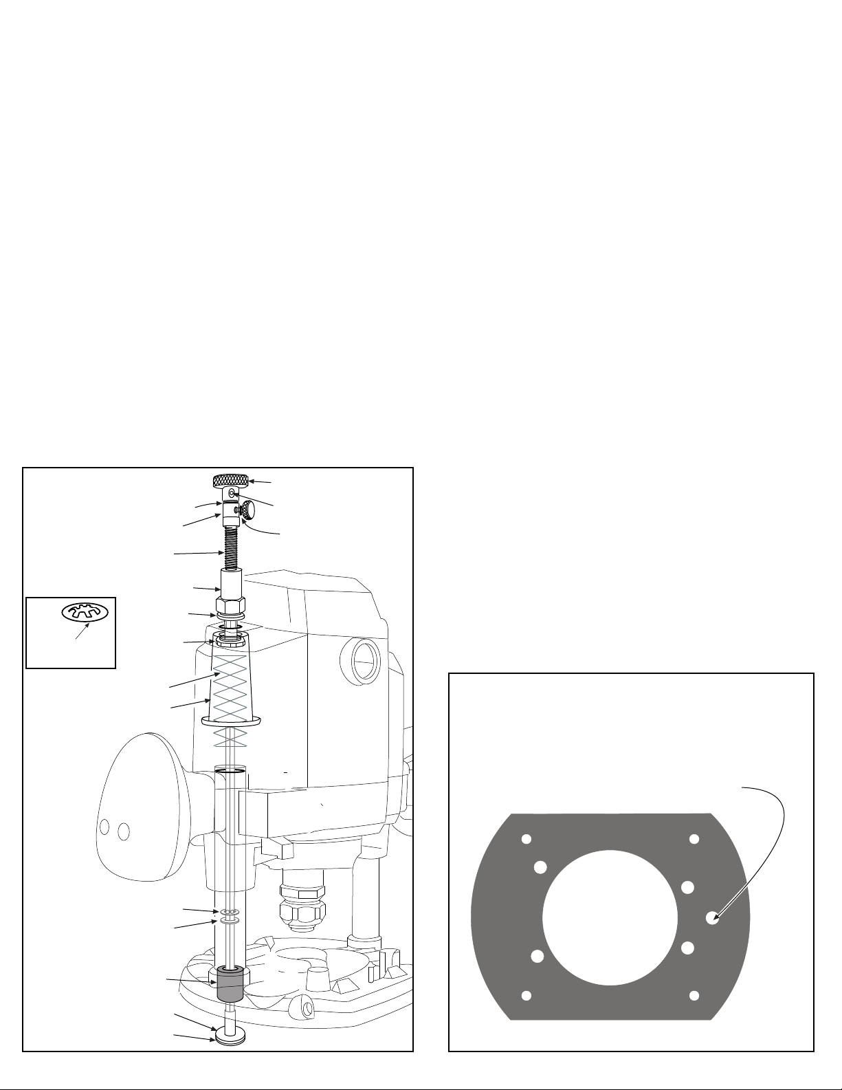
Page 11 MLCS Marvel 62
Installing #1 Mainshaft
2. Place small amount of included red grease onto both sides of #7 brass washer ,place washer down #1 mainshaft. Slide mainshaft through
#12 green bushing until flush with base. Stand base upright place #14 3/16 steel washer onto #1 mainshaft drop into the post. Select #13
hollow spring bushing, place #15 retainer clip teeth up onto the top of the mainshaft. Using #13 hollow guide flange up, advance #15 clip
down shaft. Place screwdriver or #29 wrench on flange of #13 guide, advance #15 clip into post until tight. #1 Mainshaft should be secure in
the base if you can move it back and forth, retighten #15 retainer clip Remove #13 guide.
Reassembling Top and Bottom Housings
1. The internal bottom height shaft spring will not be reinstalled, eliminating needed spring pressure, To compensate stretch both remaining
plunge springs approx one inch. Place short top spring down #1 mainshaft, place long spring in remaining post. Loosen the stop bar knob.
Reassemble housings, aligning mainshaft through the #40 housing bushing. Secure housings with four housing screws, replace the knurled
fine adjust screw lock nut and washer into the end of the bar.
Finishing Installation
1. Select #13 brass bushing ( Two #15 retainers ) #21 lead screw, #22 rapid collar, #23 O-ring, #24 thumb screw, #26 top drive, #27 yellow set
screw, #28 Allen wrench, red grease. Using ( fig 6 ) place grease on threads of #21 lead screw, Place lead screw down #1 mainshaft and thread
into #19 short nut until one inch of mainshaft extends above the head #21 lead screw. Alignment of #1 mainshaft and #21 screw hex is required.
Tip: # 29 speed wrench can be used to speed threading.
2. Press #23 O-ring onto #24 thumb screw shaft. Thread thumb screw into #22 rapid collar. Place rapid collar onto #1 mainshaft 1/2" from top
of mainshaft to top of rapid collar and tighten ( fig 6 ). Release plunge lock and slowly raise the router until lead screw contacts the rapid collar.
If the collar moves, reset to 1/2". Place one #15 retainer teeth up on top of #1 mainshaft, using #13 brass bushing as installation tool press
retainer into contact with collar,repeat with second #15 retainer and press flush with first retainer. Return #13 brass bushing to box.
Place #26 top drive onto #1 mainshaft until it contacts retainer clip, Thread #27 yellow set screw into #26 top drive using #28 Allen
wrench and tighten. Reinstall motor brushes
Subbase Plate or Router Table Insert Plate Installation
1. Use #46 locating pin to locate the Router Raizer access hole on the original subbase or router table. For detailed instructions see page 4.
2. See pages 4-5-6 for further instruction, #30 dust cover insert and #31 dust cover, are router table only. Drill a 1/2" hole through insert
plate at the Raizer access point and press #30 in from top until flush. # 31 sets in #30 and is removed during adjustments with magnet on back
edge of #29 speed handle. These components keep dust from entering the Router Raizer hex drive.
fig 6
two #15 retainer clips
#22 rapid collar
#21 lead screw
#26 top drive
#27 yellow set screw
#23 O ring
3. Periodic inspection and re-greasing of #21 lead screw
is recommended.
#19 short drive nut
#15 retainer clip
install teeth up
Original Top Spring
black spring cover
#15 retainer clip
#14- 3/16 steel washer
#12 green bushing
#18 drive nut
washer
#40 housing
bushing
fig 9
Locate raizer access point on original subbase.
Drill a 5/16" hole through original subbase only.
ROUTER TABLE insert plates require a 1/2" access hole.
Access hole Drill 5/16"
#7 brass washer
#1 mainshaft
© 2000-2006 Router Technologies
All Rights Reserved
Page 13
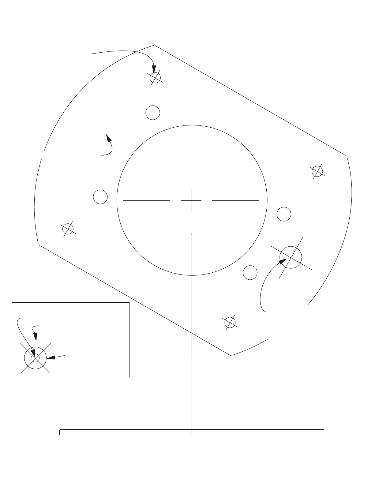
Refer to pages 4-5-6 before using template
Additional Templates Available on Website
Sub-base mounting holes
Router table fence reference line
Page 12
Router Raizer Access Point
5/16" reference circle for drilling
subbase.
1/2" = .500
.500" reference circle
for drilling table top or
insert plate.
Use this 6" scale to check accuracy when copied
Note: Cross lines for locating and drilling holes are accurate. The illustration of subbase may vary
slightly in size and design, but is accurate enough for cutting the rubber gasket if required.
© 2000-2006 Router Technologies
All Rights Reserved
Router Raizer Access Point
Drill .500" hole
through router
table insert plate
install #30 dust cover insert
into .500" hole and press flush
with top of insert plate
NOTE: This hole must be drilled 1/2" or .500"
for #30 dust cover insert to fit properly.
MLCS Marvel 62
 Loading...