

Page 1
------------------------------------------------------------------------------------------------------
This manual may not be copied or reproduced in any way without the express written
consent of MLCS Woodworking.
Copyright 2009. MLCS Woodworking. Page 1
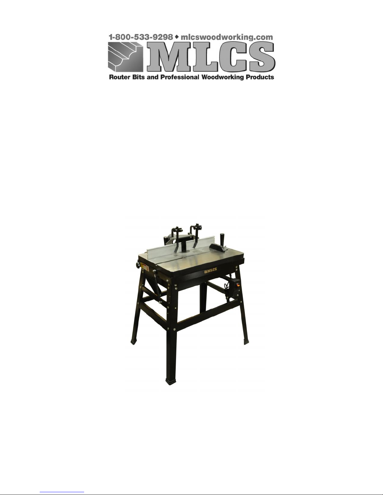
HEAVYWEIGHT ROUTER TABLE
(Item #2387/#9460)
INSTRUCTION MANUAL
Page 2

------------------------------------------------------------------------------------------------------
This manual may not be copied or reproduced in any way without the express written
consent of MLCS Woodworking.
Copyright 2009. MLCS Woodworking. Page 2
TABLE OF CONTENTS
SECTION 1: HEALTH WARNING AND SAFETY……………….3
SECTION 2: INTRODUCTION……………………………………..7
SECTION 3: CIRCUIT REQUIREMENTS..……………….………8
SECTION 4: MACHINE FEATURES AND SPECIFICATIONS…9
SECTION 5: SET-UP………………………………………………..11
Small Parts Listing……………………….………………………11
Cleanup………………………….………….……………………12
Site Consideration…………………………….………………….12
Assembly…………………………………………………………13
Cross Supports……………………………….…………………...14
Stand……………………………….……………………………..15
Table Lifting Struts……..…………..…………………………….17
Fence………………………………..…………………………….18
Fence Hold-Downs………………………….……………………19
Switch……………………………………………………………..20
Mounting The Router……………………………………….…….20
Dust Port Hook-Up………………..…………….……………..….21
SECTION 6: OPERATIONS………………………………………..22
SECTION 7: REFERENCE INFORMATION…………………….24
SECTION 8: WARRANTY AND RETURN PROCEDURES…….25
SECTION 9: EXPLODED DIAGRAM AND PARTS LIST………26
Page 3

------------------------------------------------------------------------------------------------------
This manual may not be copied or reproduced in any way without the express written
consent of MLCS Woodworking.
Copyright 2009. MLCS Woodworking. Page 3
SECTION 1: HEALTH WARNING AND SAFETY
HEALTH WARNING
Sanding, sawing, routing, drilling, and other activities may create airborne dust particles
containing chemicals known to cause cancer, birth defects, and other health
complications. For example: lead from paints, crystalline silica in masonry products like
brick and cement, arsenic and chromium from treated lumber.
Level of risk varies depending on frequency of exposure. To help mitigate detrimental
effects, always work in an area with adequate ventilation using approved safety
equipment, such as dust masks specifically rated to filter out microscopic particles.
SAFETY PRECAUTIONS WHEN WORKING WITH
POWER TOOLS
Make sure all guards are properly positioned and working correctly.
Be sure that all adjusting wrenches and keys have been removed prior to turning
on your machine.
Maintain a clean work area. Clutter can lead to unsafe conditions and accidents.
Only use power tools in a safe environment. Never operate in damp conditions or
in unventilated areas where noxious or flammable fumes may collect. Always
work in a well-lighted area.
All visitors and children should be kept away from the work area.
Childproof your work area using locks, master switches, remove starter keys, and
other devices.
Don’t force a tool beyond its capabilities. Use a tool for the job in which it was
designed and do not exceed the proper rate of use.
Wear proper clothing. NEVER wear dangling or loose clothing, necklaces,
bracelets, neckties, or other articles that could be caught in moving parts.
Likewise, cover long hair. Non-slip footwear also increases safety.
Page 4
------------------------------------------------------------------------------------------------------
This manual may not be copied or reproduced in any way without the express written
consent of MLCS Woodworking.
Copyright 2009. MLCS Woodworking. Page 4
Wear safety glasses and face or dust mask. Remember: eyeglasses do NOT
provide the same protection as safety glasses.
Extension Cord Safety: Extension cord should be in good condition and meet the
minimum wire gauge requirements listed below:
LENGTH
AMP RATING
25ft
50ft
100ft
0-61616
16
7-10
161614
11-12
161614
13-16
141212
17-20
121210
21-30
1010No
WIRE GAUGE
An undersized cord decreases line voltage, causing loss of power and overheating.
All cords should use a ground wire and plug pin. Replace any damaged cords
immediately.
Secure Your Work. When possible, use a clamp or a vise for added safety. This
keeps both hands free to operate your tool more securely.
Never Over-Reach. Proper footing and balance must be kept at all times to avoid
a dangerous fall.
Keep Your Tools Well-Cared For. Tools that are kept sharp and clean work best
and safest. Lubricate tools and change out accessories as instructed by the tool
manual.
Use Approved Accessories Only. Using accessories other than those
recommended in the Owner's Manual can cause damage and injury.
Avoid Unintentional Starts. To reduce the risk of accidental starts, machinery
should ALWAYS be unplugged prior to making adjustments or performing
service. Verify that the switch is in the OFF position before reconnecting the
power.
Inspect Damaged Parts. Any damaged parts must be thoroughly inspected before
continued use to ensure proper functioning. Pay close attention to alignment and
binding of moving parts, breakage, mounting and other potentially problematic
conditions. Promptly repair and replace any damaged parts.
Page 5

------------------------------------------------------------------------------------------------------
This manual may not be copied or reproduced in any way without the express written
consent of MLCS Woodworking.
Copyright 2009. MLCS Woodworking. Page 5
Shut Off Your Tool Before Leaving. A running tool should NEVER be left
unattended. Wait for the machine to come to a COMPLETE stop before leaving.
Stay Alert! Machinery should not be used without full mental alertness. For
example, never use machinery while tired or under the influence of drugs or
alcohol.
If you have a problem, stop using the tool immediately and contact service for
further instructions.
SAFETY INSTRUCTIONS FOR ROUTER TABLE USE
Keep your hands safe.
Do not place hands in front of or over the cutter. As your
hand moves toward the cutter, you should arc it away toward the out feed side and
then place it back behind the cutter.
Use Long Enough Stock to Keep Hands from Blades
. Special jigs or fixtures,
such as a Safety Small Parts Holder, should always be used when routing stock
less than 12 inches. If you can, rout stock before cutting and then cut to size.
Keep the cutters below the workpiece whenever practical for added safety.
Check Rotation First.
Whenever you adjust your set-up, remove the machine
from the power supply and rotate the collet by hand to ensure that the cutters can
spin freely before starting the machine.
If not using the full depth of the cutter be sure to keep any excess cutting height
below the table surface.
Watch your depth of cut.
Removing too much material is dangerous and makes
a rougher cut. Using multiple light passes enhances safety and improves the
quality of the finished cut.
Stop when You Encounter Difficulty.
Any time you have a problem; you
should stop work immediately and contact service or check with a qualified expert
for additional instruction.
Choose the Right Safety Tools.
Often, push sticks are helpful safety devices.
However, they can also be dangerous. If a push stick touches a cutter on the end
grain, it can be forcefully ejected from your hand, causing possible serious injury.
Fixtures, jigs, and hold-downs are often better options. Always use a guard or
protective device of some sort.
Page 6
------------------------------------------------------------------------------------------------------
This manual may not be copied or reproduced in any way without the express written
consent of MLCS Woodworking.
Copyright 2009. MLCS Woodworking. Page 6
Feed AGAINST
the rotation of the cutter at all times.
ALLERGY WARNING:
Certain types of wood can cause allergic reactions. Be
aware of possible reactions and use a respirator to minimize exposure to dust
particles.
You
MUST
read and fully understand the manual and operating guide for the
router to be used prior to working with it.
NEVER reach below the table while the router is running or plugged in.
!!WARNING!!
To avoid serious personal injury, please read this manual thoroughly and become very
familiar with its contents, including all safety precautions.
!!WARNING!!
In addition to these guidelines, additional precautions should be taken specific to your
own shop environment. Always use caution and common sense when operating
machinery to avoid the risk of serious injury.
Page 7

------------------------------------------------------------------------------------------------------
This manual may not be copied or reproduced in any way without the express written
consent of MLCS Woodworking.
Copyright 2009. MLCS Woodworking. Page 7
SECTION 2: INTRODUCTION
MLCS
is pleased to provide you with our Item #2387/#9460 Heavyweight Router Table,
one of our ever-expanding line of quality woodworking products and machines. The
Table will provide a long-life of trouble-free, easy operation when the guidelines in this
manual are followed. We're confident that this table will serve as proof of MLCS's
dedication to customer satisfaction and product quality.
This comprehensive manual was included to clearly cover the process of assembly,
general safety precautions, and general operating procedures. Please let us know if you
have any questions or comments regarding this documentation via the following
methods:
1) Mail to:
MLCS Ltd.
PO Box 165
Huntingdon Valley, PA 19006
2) Phone Toll-free
1-800-533-9298
3) E-mail
MLCS products are always guaranteed. For any service needs, warranty issues, or parts
requests, please contact us via one of the following methods:
1) Mail to:
MLCS Ltd.
PO Box 165
Huntingdon Valley, PA 19006
2) Phone Toll-free
1-800-533-9298
3) E-mail
Every effort is made to ensure that this manual and all its specifications, drawings, and
product diagrams are complete and correct at the time of publication. However, as we
continually modify and improve our products to better serve our customers, changes may
be made from time to time with no obligation from MLCS.
Page 8

------------------------------------------------------------------------------------------------------
This manual may not be copied or reproduced in any way without the express written
consent of MLCS Woodworking.
Copyright 2009. MLCS Woodworking. Page 8
SECTION 3: CIRCUIT REQUIREMENTS
This machine's Power Switch can be used with 2-prong double-insulated plugs or 3 prong
grounding plugs. The handy switch allows convenient and safe router control as you can
switch the power on and off from the front of the table without reaching under the table.
You can also power additional devices with the router turned on.
The power switch should be plugged into a properly grounded wall outlet.
!!WARNING!!
Improper wiring can cause a fire. Check that all system components (wiring, receptacle,
plug, and circuit breaker) are adequate for the power demands of your machinery. If you
cannot be certain, contact a qualified electrician for a review of your system and any
necessary upgrades. You should never replace a circuit breaker with one rated for a higher
amperage than other components of the circuit are designed for.
Page 9

------------------------------------------------------------------------------------------------------
This manual may not be copied or reproduced in any way without the express written
consent of MLCS Woodworking.
Copyright 2009. MLCS Woodworking. Page 9
SECTION 4: MACHINE FEATURES AND
SPECIFICATIONS
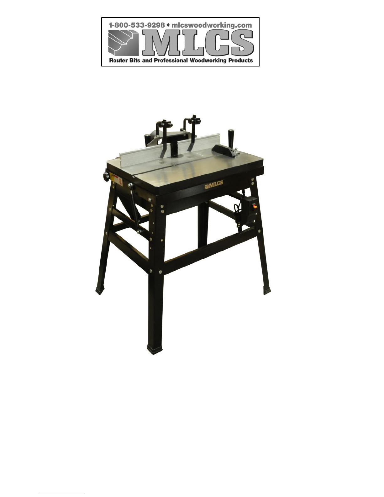
FEATURES
Accepts any brand of portable router from 3/4HP to 3-1/2HP.
Table top can be tilted 45 degrees to make router bit adjustments.
Precision split aluminum fence.
4” diameter dust hood.
Key switch prevents unauthorized operation.
Miter gauge with safety T-bar is supplied as a standard accessory.
Hold-down is supplied as a standard accessory.
SPECIFICATIONS
Suitable Portable Routers
3/4HP to 3-1/4HP
Main Table Surface
26-7/8” x 20-3/8”
Table Tilts
45 degrees
Table Inserts
2 pcs accept 1-3/8” guide template
Table Height
33-7/8”
Fence Sizes (each side)
10-5/8” x 1-31/32”
Dust Hood Outlet
4”OD
Net Weight
119 lbs
Gross Weight
123 lbs
Packing Dimensions
33-1/2” x 25-1/2” x 8-3/8”
Page 10
------------------------------------------------------------------------------------------------------
This manual may not be copied or reproduced in any way without the express written
consent of MLCS Woodworking.
Copyright 2009. MLCS Woodworking. Page 10
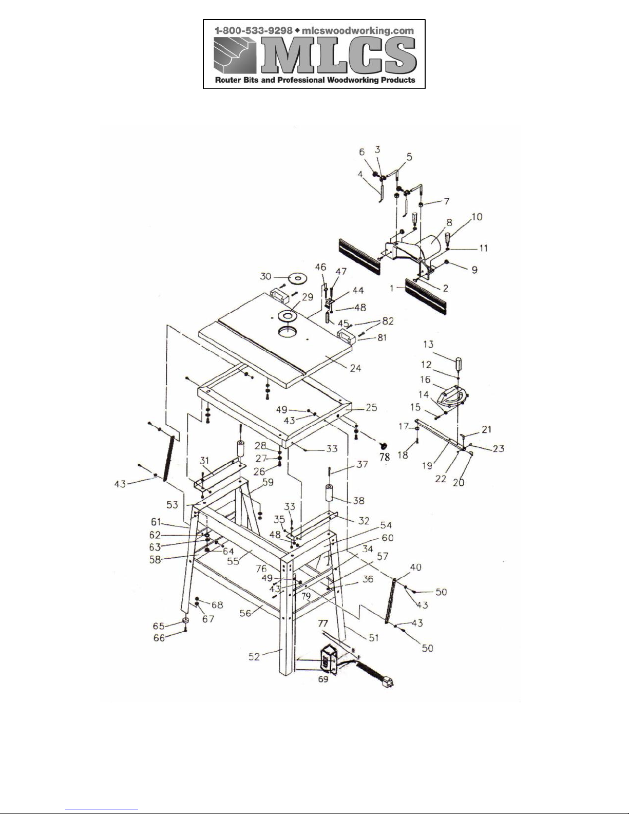
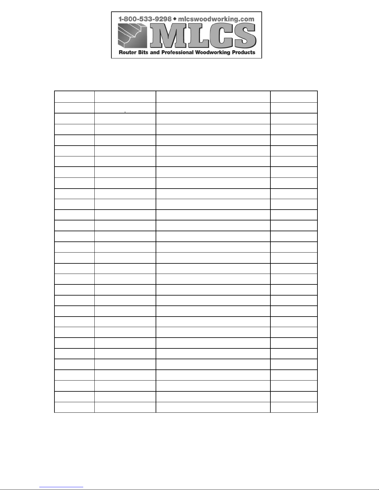
See pages 26 to 29 for the exploded diagram and parts list.
Page 11
------------------------------------------------------------------------------------------------------
This manual may not be copied or reproduced in any way without the express written
consent of MLCS Woodworking.
Copyright 2009. MLCS Woodworking. Page 11
SECTION 5: SET-UP
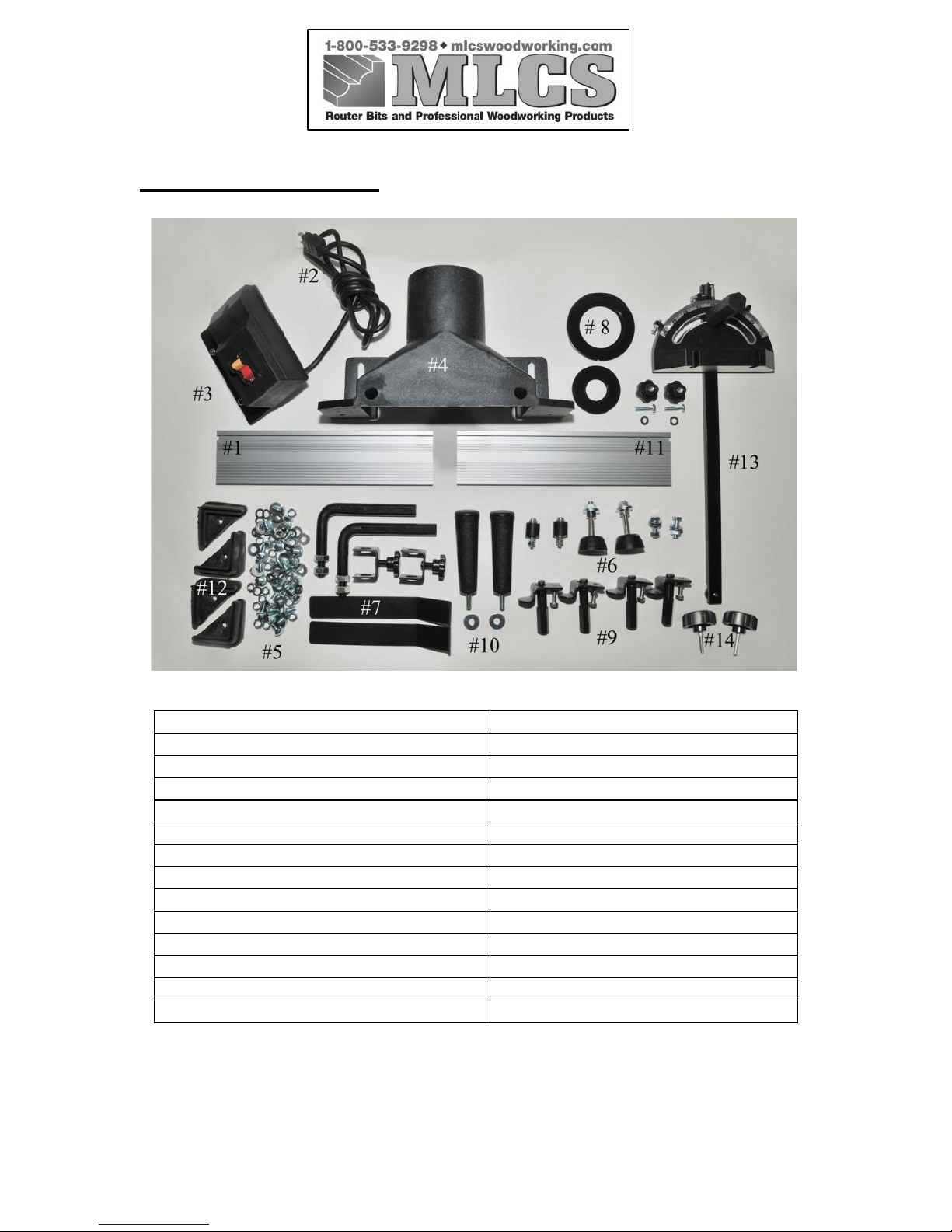
SMALL PARTS LISTING
#1, Left Fence Face Bolt & Knob (1)
5/16” x 1” bolts (2)
#2, Power Cord (1)
5/16” washers (4)
#3, Switch Box (1)
5/16” nuts (2)
#4, Dust Hood Set (1)
3/8” nuts (4)
#5, Screw Package For Stand
3/8” washers (4)
5/16” x 1/2” screws (24)
Bumpers (2)
5/16” washers (24)
#7, Fence Hold Downs (2)
5/16” nuts (24)
#8, Table Inserts (2)
5/16” lock washers (24)
#9, Router Clamping Assemblies (4)
#6, Screw Package For Table
#10, Fence Handles (2)
3/4” positioning pieces (2)
#11, Right Fence Face (1)
1/4” x 1-1/2” cross head screws (2)
#12, Rubber Feet (4)
1/4” washers (4)
#13, Miter Gauge
1/4” nuts (4)
#14, Table Locking Knobs (2)
Page 12
------------------------------------------------------------------------------------------------------
This manual may not be copied or reproduced in any way without the express written
consent of MLCS Woodworking.
Copyright 2009. MLCS Woodworking. Page 12
CLEAN UP
A wax or oil coating may be used on some metal components to prevent rust during
shipping. Any such coating should be cleaned and removed with solvent cleaner or a
citrus degreasing agent. You may need to disassemble/remove some parts for thorough
cleaning. To ensure the best performance of your machine, all moving parts and sliding
contact surfaces must be thoroughly cleaned.
SITE CONSIDERATIONS
Weight Support: MLCS
item #2387/#9460 weighs a sturdy 119 lbs. Most shop floors
should handle this weight. However, if you have doubts, you should test and reinforce
the floor prior to installation.
Safe Clearance:
Always arrange your shop to allow adequate distance between machine
and obstacles for safe operation. Carefully consider your machinery needs, the potential
size of your work pieces, and additional space needed for other stands and worktables.
The arrangement of each machine relative to other equipment should be carefully planned
to allow most efficient handling of materials.
Proper Lighting/Electrical Coverage:
Proper lighting should be bright enough to avoid
eyestrain and eliminate shadows. Position electrical outlets or arrange machinery so that
power cords and extension cords are not placed in high-traffic areas. Always follow local
codes when installing new electrical components.
!!WARNING!!
Gas and petroleum-based products are prone to explosion due to their low flash point.
NEVER use these products for cleaning your machinery.
!!WARNING!!
Solvents are flammable. To avoid the risk of explosion, fire, and/or injury, NEVER
smoke while using these products.
!!WARNING!!
Working in an area with inadequate ventilation can cause dangerous fumes to build up,
increasing the risk of explosion, fire, and risks to personal health. ALWAYS work in a
well-ventilated area.
Page 13
------------------------------------------------------------------------------------------------------
This manual may not be copied or reproduced in any way without the express written
consent of MLCS Woodworking.
Copyright 2009. MLCS Woodworking. Page 13
ASSEMBLY
Please follow these steps
IN ORDER
to assemble your machine. Then please read the
remainder of the manual completely
BEFORE
you begin operation of your new
machine.
SAFETY IS THE HIGHEST PRIORITY! Please observe these warnings during the
assembly process:
!!WARNING!!
Serious injury may occur if long hair or loose clothing is caught in moving parts of
machinery. Always roll up loose clothing and tie up long hair to keep it safely away
from your machinery.
!!WARNING!!
Machinery should
ALWAYS
be unplugged during all assembly operations or serious
personal injury could result.
!!WARNING!!
Metal parts may have sharp edges that can cause injury. Please inspect all metal edges
and handle carefully.
!!WARNING!!
Items expelled from the machine can cause eye injury. Wear appropriate safety glasses
during assembly.
Page 14
------------------------------------------------------------------------------------------------------
This manual may not be copied or reproduced in any way without the express written
consent of MLCS Woodworking.
Copyright 2009. MLCS Woodworking. Page 14
CROSS SUPPORTS
Components:
Table Assembly (Quantity 1)
Upper Front Brace (Quantity 1)
Upper Side Brace (Quantity 2)
Rubber Bumpers (Quantity 2)
Hex Bolts 5/16"-18 x 1-1/2" (Quantity 2)
Flat Washers 5/16" (Quantity 8)
Hex Nuts 5/16"-18 (Quantity 4)
Hex Bolts 5/16"-18 x 1" (Quantity 2)
Tools Needed:
12mm Wrenches or one 12mm Wrench and one 12mm Socket
Assembly:
1. Put the table assembly face down on the floor, on top of a piece of cardboard or
blanket to protect the top from getting damaged.
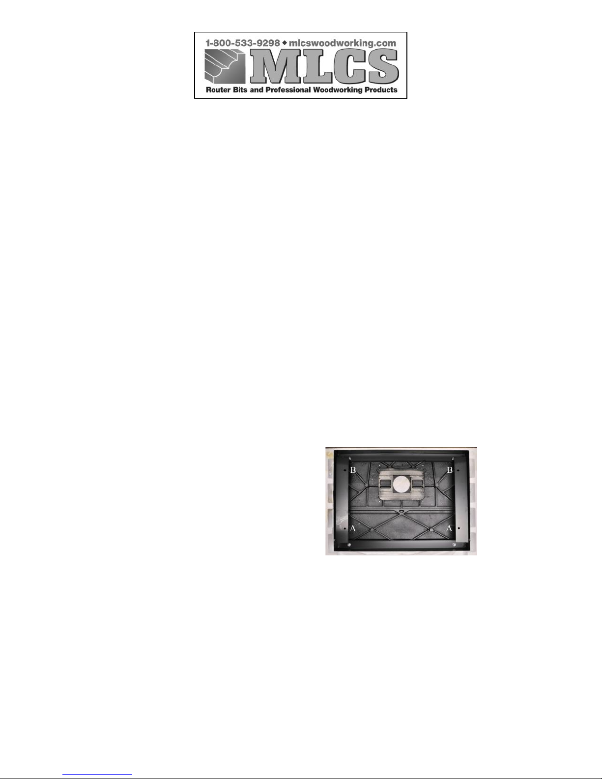
2. Align the upper side braces and the upper front brace on the table assembly
matching the bolt holes as shown in Figure A. The upper side braces are stamped
“L” left and “R” right.
3. Use 2 hex bolts, 4 flat washers, and 2 hex bolts to connect the upper side braces
and upper front brace to the table frame through bolt hole "A" position. Place 1
flat washer on each side of the assembly, with the braces and table frame
sandwiched between the two flat washers.
Figure A
Page 15

------------------------------------------------------------------------------------------------------
This manual may not be copied or reproduced in any way without the express written
consent of MLCS Woodworking.
Copyright 2009. MLCS Woodworking. Page 15
4. Use the threaded rubber bumpers, 4 flat washers, and 2 hex nuts to attach the
upper side braces to the table frame through bolt hole "B" position. Remove one
hex nut and 1 flat washer from the threaded rubber bumper. With the rubber head
of the bumper facing the bottom of the table, insert the threaded part through the
holes in the table frame and the upper side braces. Replace the flat washer that
was removed earlier and secure with the hex nut that was also removed earlier.
The height of the rubber bumper can be adjusted by moving the hex nuts up or
down the threaded part of the rubber bumper, thereby leveling the table top.
STAND
Components:
Stand Legs (Quantity 4)
45-degree Diagonal Support Brace (Quantity 2)
Front Lower Brace (Quantity 1)
Rear Lower Brace (Quantity 1)
Side Brace (Quantity 2)
Intermediate Strut Side Brace (Quantity 2)
Carriage Bolts 5/16"-18 x 5/8" (Quantity 32)
Flat Washers 5/16" (Quantity 32)
Lock Washers 5/16" (Quantity 32)
Hex Nuts 5/16"-18 (Quantity 32)
Tools Needed:
12mm Wrench or Socket
Assembly:
1. Use 12 carriage bolts, 12 flat washers, 12 lock washers, and 12 hex nuts to attach
the stand legs to the upper front and upper side braces. At this time only finger
tighten the hex nuts as you may need to maneuver the parts during assembly.
2. Use 8 carriage bolts, 8 flat washers, 8 lock washers and 8 hex nuts to attach the
lower front, rear and side braces to the legs. The lower brace is the one with the
two additional intermediate holes in it. At this time, only finger tighten the hex
nuts, as you may need to maneuver the parts during assembly. Use 4 carriage
bolts, 4 flat washers, 4 lock washers and 4 hex nuts to attach the intermediate strut
side braces to the legs. The strut mounting hole should be toward the front of the
table.
Page 16
------------------------------------------------------------------------------------------------------
This manual may not be copied or reproduced in any way without the express written
consent of MLCS Woodworking.
Copyright 2009. MLCS Woodworking. Page 16
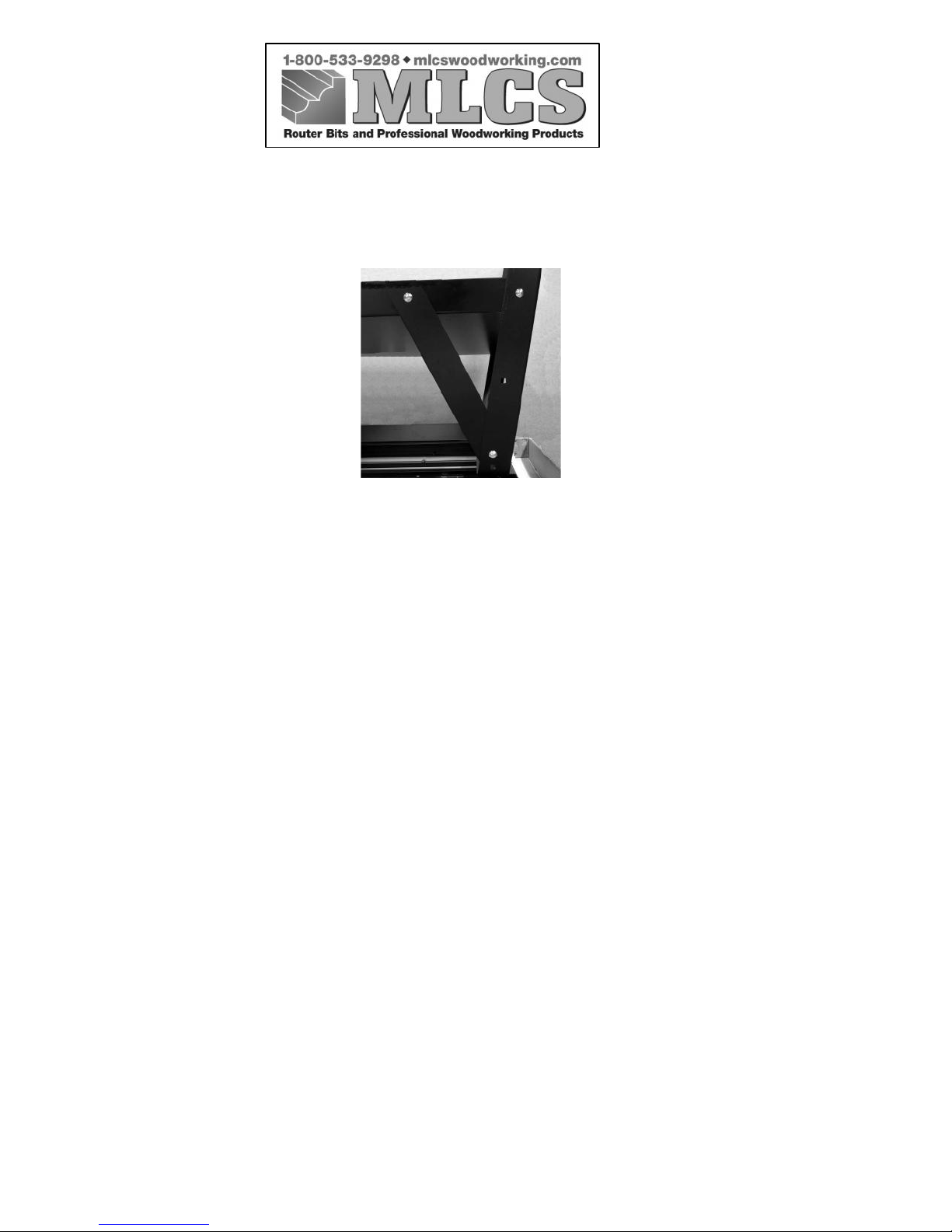
3. Use 4 carriage bolts, 4 flat washers, 4 lock washers, and 4 hex nuts to connect the
45-degree support braces to the back side of the tray and stand legs.
4. Use the proper tools to tighten all hex nuts to secure the stand together.
5. Place the rubber feet on the bottom of the legs.
6. With the help of a second person, Carefully turn the table right side up so it sits
firmly on the rubber feet.
7. Remove the protective paper from the cast iron table surface. Use a solvent
cleaner or degreaser to remove the coating from the cast iron table surface. Follow
the directions on the label of the cleaner and allow for proper ventilation when
using any solvents. Use caution to avoid getting any of the cleaner on the painted
parts of the table and stand as this may cause the paint to be removed. Properly
dispose of any soiled rags as some solvents pose a flammable risk.
Page 17
------------------------------------------------------------------------------------------------------
This manual may not be copied or reproduced in any way without the express written
consent of MLCS Woodworking.
Copyright 2009. MLCS Woodworking. Page 17
TABLE LIFTING STRUTS
Components:
Hydraulic Struts (Quantity 2)
Hex Bolts 1/4"-20 x 3/4" (Quantity 4)
Flat Washers 1/4" (Quantity 16)
Nylock Nuts 1/4” (Quantity 4)
Table Locking Knobs (Quantity 2)
Lifting Handles (Quantity 2)
Allen Head Screws 6mm x 25mm
Tools Needed:
1/2” Wrench (2), 4mm Allen Wrench
Assembly:
1. Slide a flat washer on the hex bolt.
Insert the hex bolt through the eye
on the chromed end of the hydraulic
strut.
2. Place three more flat washers on the
bolt and pass the bolt threads
through the hole in the table frame.
3. From the inside of the frame, secure the strut to the table top frame using the
nylock nut. Do not completely tighten the nylock nut as the strut will need to be
able to pivot when the top is raised or lowered.
4. Repeat this same operation for the other end of the hydraulic strut (barrel end),
only pass the bolt through the intermediate side strut brace.
5. Repeat for the other side of the table.
6. The struts will allow the table to stay up at a 45 degree angle. Use the two
Table lock knobs to secure the table down in a working position. The two
table pull down handles can be attached to the back edge of the table to aid
in holding the table down while the table lock knobs are tightened.
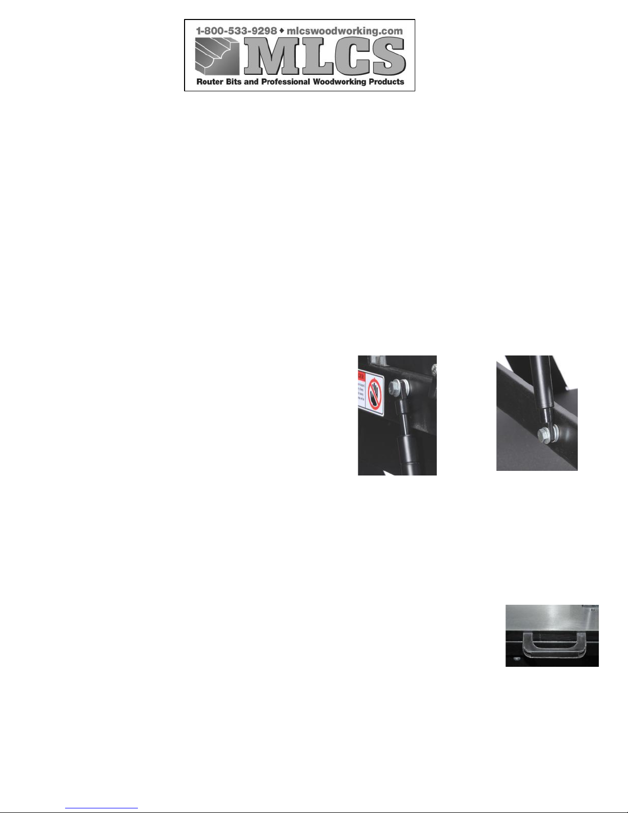
Top of Strut attached
to Table
Bottom of Strut
attached to Stand
Page 18
------------------------------------------------------------------------------------------------------
This manual may not be copied or reproduced in any way without the express written
consent of MLCS Woodworking.
Copyright 2009. MLCS Woodworking. Page 18
FENCE
Components:
Fence Half (Quantity 2)
Sliding Screw 1/4” x 1” (Quantity 2)
Star Knob 1/4”-20tpi (Quantity 2)
Dust Hood (Quantity 1)
Assembly:
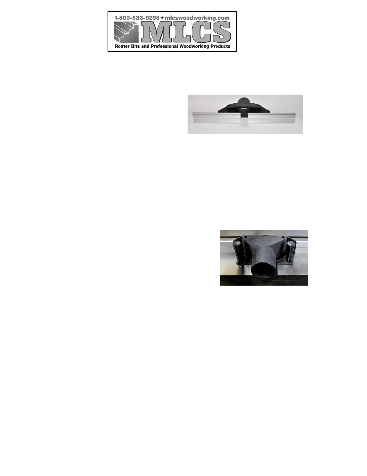
1. Slide the head of the sliding screw into the t-slot on the back of the fence face
(smooth side, slot in middle of the fence).
2. Insert the sliding screw through the hole in the dust hood. Secure the fence face
to the hood using the female star knob.
Installing:
3. After assembling the fence/dust hood, mount
the assembly onto the table.
4. Lock the fence assembly onto the table by
tightening the two lock handles at one of the
various mounting positions for the bit you are
using.
Page 19
------------------------------------------------------------------------------------------------------
This manual may not be copied or reproduced in any way without the express written
consent of MLCS Woodworking.
Copyright 2009. MLCS Woodworking. Page 19
FENCE HOLD-DOWNS
Components:
Hold-Down Assemblies (Quantity 2)
Tools Needed:
19mm Wrench
Assembly:
1. Take one hex bolt off each L-bar.
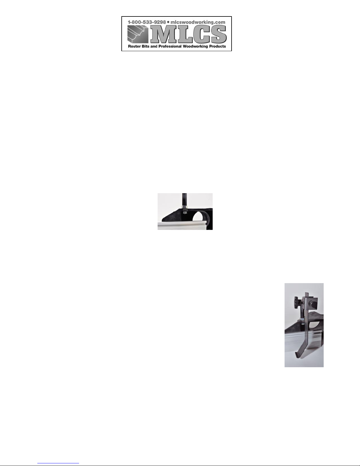
2. Attach the L-bar to the fence assembly by inserting the threads on the L-bar
through the dust hood's mounting holes. Then use the previously removed hex nut
to secure the L-bar in place from underneath the dust hood.
3. Tighten the hex nuts until the brackets are secured perpendicular to the fence
faces.
4. Place the hold down holder onto the L-bar. Orient the hold down holder so the
threaded star knob so it will contact the L-bar on the flattened surface.
5. Slide the hold down through the hold down holder. The bend in the hold
down should be oriented toward the table surface and to the left.
6. Tighten the threaded star knob to lock the hold-down in position. Exact
placement is not essential at this point in the process.
Page 20
------------------------------------------------------------------------------------------------------
This manual may not be copied or reproduced in any way without the express written
consent of MLCS Woodworking.
Copyright 2009. MLCS Woodworking. Page 20
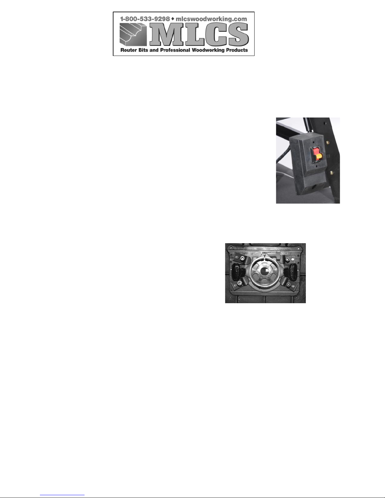
SWITCH
Components Needed:
Switch Box (Quantity 1)
Tools Needed:
Phillips Head Screwdriver, Adjustable Wrench
Assembly:
1. Use the Phillips head screws, flat washers, and hex
nuts to attach the power box to the front right leg using the
appropriate through holes in the stand leg.
MOUNTING THE ROUTER
Components Needed:
Router Clamps (Quantity 4)
Tools Needed:
10mm Wrench, 14mm Wrench
Assembly:
1. Raise the table and lock the braces in place on both sides, using the positioning
pieces. Be sure the lock tabs have been firmly positioned on the screws in the
table positioners.
2. Insert the 4 router clamps into the T-slots underneath the table.
Page 21

------------------------------------------------------------------------------------------------------
This manual may not be copied or reproduced in any way without the express written
consent of MLCS Woodworking.
Copyright 2009. MLCS Woodworking. Page 21
3. Loosen the clamps so that the base of your router can press
flat against the table bottom. Be certain that the router collet
is centered in the table opening.
4. Firmly attach the router base to the table by tightening the
thickness bolts and jam nuts on each of the 4-router clamps.
5. Tighten the clamps to firmly hold the router in position.
DUST PORT HOOK-UP
Never use this table without appropriate dust collection. Be sure to connect the dust port
to a vacuum or dust collector system.
Page 22
------------------------------------------------------------------------------------------------------
This manual may not be copied or reproduced in any way without the express written
consent of MLCS Woodworking.
Copyright 2009. MLCS Woodworking. Page 22
SECTION 6: OPERATIONS
BEFORE ROUTING
STAY SAFE:
Please observe all the following warnings during operation of your table.
ROUTING ON YOUR TABLE
There are 2 basic routing operations that can be performed on your table:
Groove Cutting, and Profile Routing.
Groove Cutting
, makes a groove or dado in the face of a board.
1. Insert a router bit into your router per the instructions for your router and bit.
2. Insert the round table insert into the recessed hole in the table. Choose the
smallest insert opening that does not interfere with the bit movement. Raise the
router bit to the desired height.
3. Reposition the fence so that the router bit is the desired distance away from the
router fence.
!!WARNING!!
Serious injury may occur if long hair or loose clothing is caught in moving parts of
machinery. Always roll up loose clothing and tie up long hair to keep it safely away from
your machinery.
!!WARNING!!
ALWAYS wear safety glasses, respirator, and hearing protection when using this
machine. Otherwise, damage to lungs, ears, and eyes could result.
!!WARNING!!
Avoid serious injury by familiarizing yourself with this entire manual prior to using
your item #9595 Heavyweight Router Table.
Page 23

------------------------------------------------------------------------------------------------------
This manual may not be copied or reproduced in any way without the express written
consent of MLCS Woodworking.
Copyright 2009. MLCS Woodworking. Page 23
Profile Cutting
typically uses a bit with a ball bearing. The bearing follows along the
uncut edge, controlling the depth of cut, while the cutter removes wood from the edge
face of a board.
1. Insert a router bit into your router per the instructions for your router and bit.
2. Insert the round table insert into the recessed hole in the table. Choose the
smallest insert opening that does not interfere with the bit movement.
3. Raise the router bit to the desired height.
4. Adjust the fence opening width to allow proper router bit clearance, but provide
the proper support to safely make your cut.
5. Move the fence back just enough so the ball bearing can control the cut depth.
6. Move the fence back toward the bearing as close as possible to provide added
support and safety.
Page 24

------------------------------------------------------------------------------------------------------
This manual may not be copied or reproduced in any way without the express written
consent of MLCS Woodworking.
Copyright 2009. MLCS Woodworking. Page 24
SECTION 7: REFERENCE INFORMATION
For parts or assembly assistance, please contact our technical support department. They
will be happy to assist. For comments and questions regarding this manual, our
MLCS
warranty and return policy, and any general assistance, please contact us via one of the
following methods:
Toll-Free Phone:
1-800-533-9298
E-mail:
Postal Mail:
MLCS Ltd., PO Box 165, Huntingdon Valley, PA 19006
We have made every effort to detail all necessary safety guidelines for operating this
equipment throughout this manual. Nonetheless, please keep in mind that every shop and
situation is different and all these rules should be considered and applied with common
sense given the specifics of your own situation.
This manual contains only basic guidelines and instructions for general, safe operation of
this machine. To become a skilled and accomplished woodworker and fully realize the
potential of this machine, you will need to avail yourself of additional resources. Trade
journals, woodworking magazines, the local library, and community colleges can all be
indispensable sources of guidance and knowledge.
Page 25

------------------------------------------------------------------------------------------------------
This manual may not be copied or reproduced in any way without the express written
consent of MLCS Woodworking.
Copyright 2009. MLCS Woodworking. Page 25
SECTION 8: MLCS WARRANTY AND RETURN
PROCEDURES
Every
MLCS
product has a 3-year Guarantee from the original date of purchase
indicated on the invoice or packing list. Defects due (directly or indirectly) to misuse,
abuse, negligence, accidents, repairs or alterations or lack of maintenance are expressly
excluded from this warranty. This is
MLCS
's sole written warranty for this product. Any
and all other warranties that may be implied by law are hereby limited to the duration of
this written warranty. In no event shall
MLCS
's liability exceed the purchase price paid
for this product and any resulting legal actions will be tried in the courts of Huntingdon
Valley, PA, County of Montgomery.
MLCS
shall in no way be held liable for death, injuries to persons or property or for
incidental, contingent, special, or consequential damage arising from the use of our
products.
For warranty related service, please contact us by mail or by toll-free phone at 1-800533-9298. Please be prepared to provide all purchase details, including name and address
of purchaser, date of purchase, invoice number, and issues with the product so that we
may properly assist you. Additional instructions will be provided at the time of contact
for the most expedient resolution to your particular issues. Any items returned for refund
or replacement should include proper proof of purchase, such as an invoice or packing
list.
MLCS
reserves the right to change the specifications of this product at any time as we
strive to always improve the quality of our products based on continued research and
development and customer feedback. It is our primary goal to ensure that our products
are of high quality and durability and we sincerely hope you will never need to take
advantage of this warranty.
Thank you again for your purchase and your support of
MLCS Woodworking
with your
continued business. We look forward to serving you again in the near future and, for
now; wish you happy and safe woodworking.
Page 26
------------------------------------------------------------------------------------------------------
This manual may not be copied or reproduced in any way without the express written
consent of MLCS Woodworking.
Copyright 2009. MLCS Woodworking. Page 26
EXPLODED DIAGRAM
Page 27
------------------------------------------------------------------------------------------------------
This manual may not be copied or reproduced in any way without the express written
consent of MLCS Woodworking.
Copyright 2009. MLCS Woodworking. Page 27
PARTS LIST
PART No.
REFERENCE No.
DESCRIPTION
QTY
1
50000111a
FENCE HALF
2
2
50000112
SLIDING SCREW 1/4"*1"
2
3
50000117
HOLD-DOWN MOUNT
2
4
50000118
HOLD-DOWN
2
5
50000119
LBAR
2
6
50000120
KNOB 5/16"*5/8"
2
7
S0110812
1/2" HEX NUT
4
8
50300125
DUST HOOD
1
9
10505015
STAR KNOB NUT 1/4"-20TPI
2
10
10104045t
HEAVY HANDLE
2
11
S0210501
FLAT WASHER 5/16"
2
12
S0210400
FLAT WASHER 1/4"
1
13
10104045
MITER GAUGE HANDLE
1
14
S0110100
HEX NUT 5/32"
3
15
S0030108
CROSS SCREW 5/32"-32TPI
3
16
10104046
MITER GAUGE BODY
1
17
10104047
SLIDING BLOCK
1
18
S0040400
SCREW 1/4"-20TPI
1
19
101040481
GUIDE BAR
1
20
10104049
LOCATING PLATE
1
21
10104050
POINTER
1
22
S0050404
SET SCREW 1/4"-20TPI*1/4"
1
23
S0310306
ROLL PIN 3mm*6mm
1
24
50300201
TABLE TOP 26-7/8"*20-3/8"
1
25
50300202
TABLE FRAME
1
26
S0020512
HEX BOLT 5/16"-18TPI*3/4"
4
27
S0230506
LOCK WASHER 5/16"
4
28
S0210500
FLAT WASHER 5/16"
4
29
50000217
TABLE INSERT (60mm)
1
Page 28
------------------------------------------------------------------------------------------------------
This manual may not be copied or reproduced in any way without the express written
consent of MLCS Woodworking.
Copyright 2009. MLCS Woodworking. Page 28
PART No.
REFERENCE No.
DESCRIPTION
QTY
30
50000219
TABLE INSERT (29mm)
1
31
50300208
TABLE LEFT SUPPORT
1
32
50300209
TABLE RIGHT SUPPORT
1
33
S0020501
HEX BOLT 5/16"-18TPI*1"
4
34
S0210623
FLAT WASHER 3/8"
10
35
S0120201
HEXNUT 5/16"-18TPI
2
36
S0110600
HEXNUT 3/8"-16TPI
4
37
50000307b
BUMPER
2
40
LIFTING STRUTS
2
43
S0210400
FLAT WASHER 1/4"
10
44
50000220
MOTOR CLAMP PIECE
4
45
50000221
HEXAGONAL CLAMP PIECE
4
46
50000222
SLIDING SCREW
4
47
S0020425
HEX BOLT 1/4"-20PTI*1-3/4"
4
49
S0120200
NYLOCK HEX LOCK NUT 1/4"
4
50
S0020412
HEX BOLT 1/4"-20TPI*3/4"
4
52
STAND LEGS
4
53
50300303L
UPPER LEFT ANGLE PLATE
1
54
50300303R
UPPER RIGHT ANGLE PLATE
1
55
50300304
FRONT UPPER BRACE
1
56
50300305
FRONT LOWER BRACE
1
57
50300306
REAR LOWER BRACE
1
58
50300307
LOWER SIDE BRACE
2
59
50000308
LEFT BRACKET
1
Page 29
------------------------------------------------------------------------------------------------------
This manual may not be copied or reproduced in any way without the express written
consent of MLCS Woodworking.
Copyright 2009. MLCS Woodworking. Page 29
PART No.
REFERENCE No.
DESCRIPTION
QTY
60
50000306
RIGHT BRACKET
1
61
S0060509
CARRIAGE BOLT 5/16"-18TPI*5/8"
24
62
S0210501
FLAT WASHER 5/1 6"
24
63
S0230506
LOCK WASHER 5/16"
24
64
S0110500
HEXNUT 5/16"-18TPI
24
65
10107098
RUBBER FEET
4
69
SWITCH BOX (PRE-ASSEMBLED)
1
76
S0030324
SCREW 3/16"-24TPI*5/8"
2
77
S0110300
HEXNUT 3/16"-24TPI
2
78
LOCKING KNOBS 5/16"-18TPI*1-1/4"
2
81
TABLE LIFTING HANDLES
2
82
ALLEN HEAD MACHINE SCREWS
4
 Loading...