

Page 1
LAMP INSTALLATION AND REPLACEMENT
All fittings will accept standard GU10 230V halogen lamps or LED equivalents.
ACCESSORIES
A range of track accessories are available as detailed below:-
TRKDES 230V single circuit track dead end cap - satin nickel
TRKDEW 230V single circuit track dead end cap - white
TRKFCS 230V single circuit track flexible connector - satin nickel
TRKFCW 230V single circuit track flexible connector - white
TRKLCS 230V track in-line connector - satin nickel
TRKLCW 230V track in-line connector - white
TRKPFS 230V single circuit track power feed - satin nickel
TRKPFW 230V single circuit track power feed - white
TRKRAS 230V track L right angle connector - satin nickel
TRKRAW 230V track L right angle connector - white
TRKTS 230V track T-connector - satin nickel
TRKTW 230V track T-connector - white
TRKXS 230V single circuit track connector X - satin nickel
TRKXW 230V single circuit track connector X - white
NOTE:
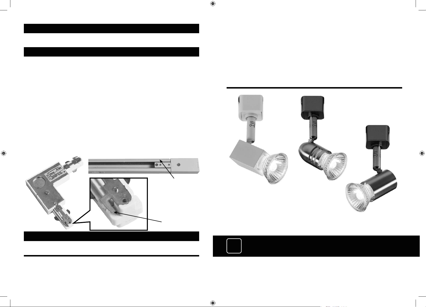
ALL track joining accessories are designed and manufactured to fit into the track 1 way only as
detailed below. Please do not try to force any track joining accessory into the wrong end of the track.
INSTALLATION & MAINTENANCE MANUAL
TRKSP
POLARITY GROOVE
EARTH TAB
MUST BE
INSERTED INTO
“POLARITY
GROOVE” SIDE
OF TRACK ONLY
TRKSP1
Single circuit track lighting
TRKSP3
TRKSP2
CLEANING
Clean with a soft dry cloth only.
TRK_INSTRUCTIONS_NEW.indd 1 22/07/2014 08:46
IP
20
Page 2
GENERAL INSTRUCTIONS:
These instructions should be read carefully and retained after installation for further reference and
maintenance
.
SAFETY
• Before installation, maintenance or lamp replacement, ensure the mains supply to the track is
switched off and the circuit supply fuses are removed or circuit breaker turned off
• It is recommended that a qualified electrician is consulted or used for the installation of this
luminaire and installed in accordance with the current edition of the IEE Wiring and
Building Regulations
• Check that the total load on the circuit, including when this track is fitted, does not exceed the
rating of the circuit cable, fuse or circuit breaker
• This product is Class I construction and should be earthed
• This product is IP20 rated
• GU10 50W max or LED equivalent
• 230V/240V AC
• 16A
• CE approved
• This product is suitable for dimming when used in conjunction with a dimmable lamp.
Please ensure suitability for dimming with the lamp manufacturer prior to use.
• Track spots fitted with halogen lamps operate at a high temperature ensure all fixtures are
mounted out of hand’s reach.
INSTALLATION
INSTALLING THE TRACK AND LIVE END
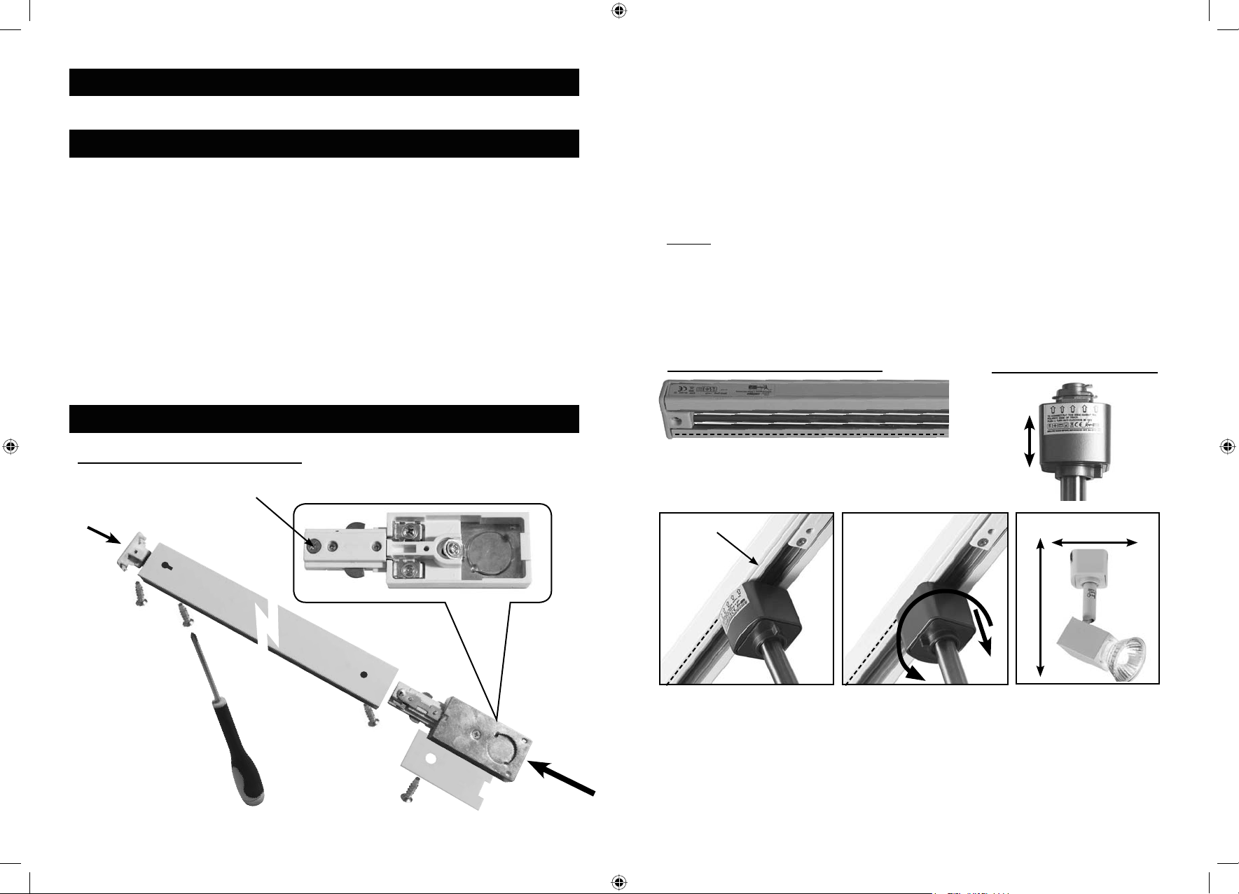
SECURING SCREW
LIVE END
1) Choose a suitable location to mount the track ensuring not to infringe with any gas/water pipes or
electrical cables that could be below the surface. Ensure that the location surface will be able to
support the weight of the track and track lights when fitted
2) Remove the terminal cover from the Live End by removing the terminal cover screw
3) Choose the method of cable entry and remove the knockout either in the plastic end (surface
wiring) or metal back (concealed wiring)
4) Using the track as a template, mark the mounting surface for the installation holes and cable
entry point
5) Drill the cable entry and installation holes and fix the track using the wall plugs and screws
supplied. (It may be necessary to use a different type of wall plug depending on the wall/surface)
WIRING
Insert the power cable into the Live End through the chosen entry hole.
Connect the power cable to the Live End - BROWN to LIVE (L), BLUE to NEUTRAL (N), and GREEN/
YELLOW to EARTH.
Replace the terminal cover and terminal cover screw.
NOTE: The Live End will only fit one end of the track and is supplied fitted to the correct end. Do NOT
try to force the Live End into the incorrect end if the Live End is removed.
INSTALLING THE TRACK SPOTLIGHTS
The polarity groove is a shallow groove on the surface of
the track.
SPOTLIGHT TRACK ADAPTOR
Single pin
Sliding
cover
twin pins
Location
arrows
Location
arrows
POLARITY GROOVE
12
LN
TO INSTALL:
1) Align arrows on spotlight track adaptor with the polarity groove on the track.
2) Push up into track and rotate ANTI-CLOCKWISE 90˚while gently pulling back
on the sliding cover until it locks into place.
TERMINAL COVER
SCREW
TRK_INSTRUCTIONS_NEW.indd 2 22/07/2014 08:46
TO REMOVE: Hold the spotlight and gently pull down on the
track adaptor and rotate CLOCKWISE 90˚.
ALL SPOTLIGHTS
50mm
140mm
 Loading...