

Page 1

INSTALLATION & MAINTENANCE MANUAL
BATSCW4 / BATSCW5 / BATSCW6
Page 2

GENERAL INSTRUCTIONS
These instructions should be read carefully and retained after installation by the end user for
future reference and maintenance.
These instructions should be used to aid installation of the following products:
BATSCW4 / BATSCW5 / BATSCW6
SAFETY
• This product must be installed in accordance with the latest edition of the IEE Wiring Regulations (BS7671)
and current Building Regulations. If in any doubt, consult a qualified electrician
• Please isolate mains prior to installation or maintenance
• Check the total load on the circuit (including when this luminaire is fitted) does not exceed the rating of the
circuit cable, fuse or circuit breaker
• Please note the IP (Ingress Protection) rating of this product when deciding the location for installation
• This product is for indoor use only
• This product is Class I and must be earthed
• This product is IP20 rated
INSTALLATION
Note - If this product is being used in conjunction with an external PIR or sensor, please confirm with the
manufacturer of the sensors that they are compatible with LED luminaires.
• Provide power to the required point of installation
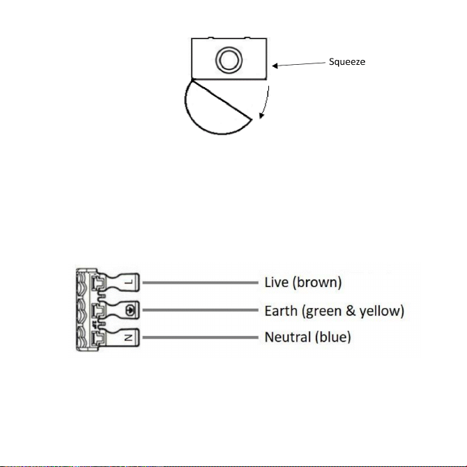
• Squeeze the sides and hinge the diffuser away from the fitting (see Fig. 1)
Page 3
INSTALLATION & MAINTENANCE MANUAL
(BS7671) and current Building Regulations. If in any doubt, consult a qualified electrician
the circuit cable, fuse or circuit breaker
or electrical cables. The fitting can also be mounted over conduit boxes – the distance between fixing
centres is 600mm
the push-fit terminal block in order to achieve loop-in/loop-out wiring
Fig. 1
• Mark the location of the fixing holes and drill the holes ensuring not to infringe with any gas/water pipes or
electrical cables. The fitting can also be mounted over conduit boxes – the distance between fixing centres
is 600mm
• Feed the mains cable through the cable entry point, and secure the luminaire to the surface
• Ensuring correct polarity is observed, carefully wire as shown in Fig. 2. Two cables can be inserted into the
push-fit terminal block in order to achieve loop-in/loop-out wiring
Fig. 2
• Select the desired driver output and colour temperature via the switches on the driver (see Fig. 3)
Page 4
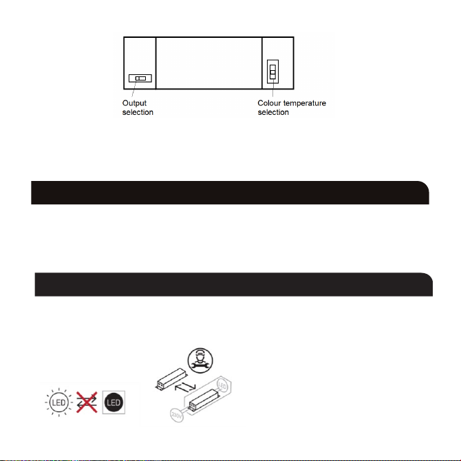
Fig. 3
• Switch on and check for correct operation
WARNING
This product must be disconnected from the circuit if subjected to any high voltage or insulation resistance
testing. Irreparable damage will occur if this instruction is not followed.
GENERAL
This product contains a light source of energy efficiency class D to Regulation (EU) No. 2019/2015 and (UK)
2021 No. 1095.
This product contains a non-replaceable LED light source and a control gear which can be replaced by a
professional.
Page 5

Clean with a soft dry cloth only, do not use aggressive cleaning products or solvents which may damage the
product.
This product is non-dimmable.
This product should be dismantled for disposal when it reaches the end of its life. Please see website for
dismantling instructions.
This product should be recycled in the correct manner when it reaches the end of its life. Check local authorities
for where facilities exist.
WARRANTY
This product has a warranty of 5 years from date of purchase. Failure to install this product in accordance with
the current edition of the IEE Wiring Regulations (BS7671), improper use, or removal of the batch code will
invalidate the warranty. If this product should fail within its warranty period, it should be returned to the place
of purchase for a free of charge replacement. ML Accessories does not accept responsibility for any installation
costs associated with the replacement product. Your statutory rights are not affected. ML Accessories reserve
the right to alter product specification without prior notice.
Page 6
Supplied By:
ML Accessories Ltd, Unit E Chiltern Park, Boscombe Road, Dunstable LU5 4LT,
nnuks Holding GmbH, Niederkasseler Lohweg 18,
(UK) Manufacturer
www.mlaccessories.co.uk
(EU) Authorised Representative
40547 Düsseldorf, Germany,
Email: [email protected]
-20
~50°C
TA
52
DCAPR22_V1
 Loading...