

Page 1
SW-95, SW-85, SW-62
SW-54, SW-52, SW-51
SW-50
Miller & Kreisel Sound, Inc.
9351 Deering Avenue
Chatsworth, CA 91311-5858 USA
(818) 701-7010 fax (818) 701-0369
www.mksound.com
©2002 Miller & Kreisel Sound, Inc.
frameless in-wall speaker
operation manual
TM
Page 2

Please record the following information for your records:
Serial Number:
Date of Purchase:
Dealer Name:
Dealer Address:
City/State/Zip:
Country:
Invoice Number:
TABLE OF CONTENTS
1. INTRODUCTION........................................................................................3
COMPONENT OVERVIEW...................................................................................3
2. INSTALLATION INTO EXISTING WALLS..........................................................4
3. SPEAKER WIRING..........................................................................................4
4. SPEAKER WIRING FOR SW-85 AND SW-95 ONLY..........................................4
SOUND VARIATIONS (SW-85 & SW-95 only)...................................................4
REMOTE SWITCHING OF V ARIATIONS OF SOUND (SW-85 & SW -95 only)......6
5. MOUNTING THE SPEAKER IN THE WALL
................................................................6
6. SATELLITE AND SUBWOOFER PHASE TEST................................................8
7. SPEAKER DAMAGE & HOW TO AVOID IT.......................................................8
8. IF YOU NEED SERVICE...................................................................................9
9. M&K TEN YEAR WARRANTY.........................................................................9
10. REMOVING THE SPEAKER FROM THE WALL...............................................9
11. PRE-CONSTRUCTION BRACKET INSTALLATION.........................................10
12. SPECIFICATIONS...............................................................................................11
FRAMELESS IN-WALL SPEAKER
Page 3

3
FRAMELESS IN-WALL SPEAKER
1. INTRODUCTION
Congratulations! Your new M&K in-wall speaker system will give you years of unmatched enjoyment and excitement while
listening to your favorite musical and audio/video sources. We encourage you to read this owner’s manual, as there is a great
deal of information provided here to help you achieve the best possible performance.
If you have any questions about your in-wall speaker system, please contact your M&K dealer or call the M&K factory
directly at (818) 701-7010, from 8:30 AM to 5:00 PM Pacific Time, Monday through Friday. We will be happy to help you with any
question. Additional information may also be obtained on our web site: www.mksound.com
or you may send us an e-mail to
suppor
[email protected].
If you are installing your new speaker into existing walls, please see section 2, on page 4.
If you are installing your speakers into walls that are being constructed, go to section 12, page 10 or the Pre-Construction
Bracket Instructions that are included with your Pre-Construction Bracket Kit SPRE50, SPRE85, or SPRE95.
All M&K In-wall speakers is well suited for either wall mount or ceiling mount applications. Although, the SW-50, with its
circular grille, is the aesthetically preferred speaker for ceiling mount locations.
Speaker Grille
Foam Frame
(Installed inside
wall)
Foam Dampening Pad
(Installed inside wall)
Pre-Construction Assembly*
(Sold separately)
Inwall Speaker Assembly
THESE ARE THE MAJOR COMPONENTS OF YOUR NEW SPEAKER SYSTEM
*not required; available from your dealer as part number SPRE85 (for use with SW-85, SW-52);
SPRE95 (for use with SW-95, SW-62); or SPRE50 (for use with SW-50, SW-51, SW-54).
Page 4
4
FRAMELESS IN-WALL SPEAKER
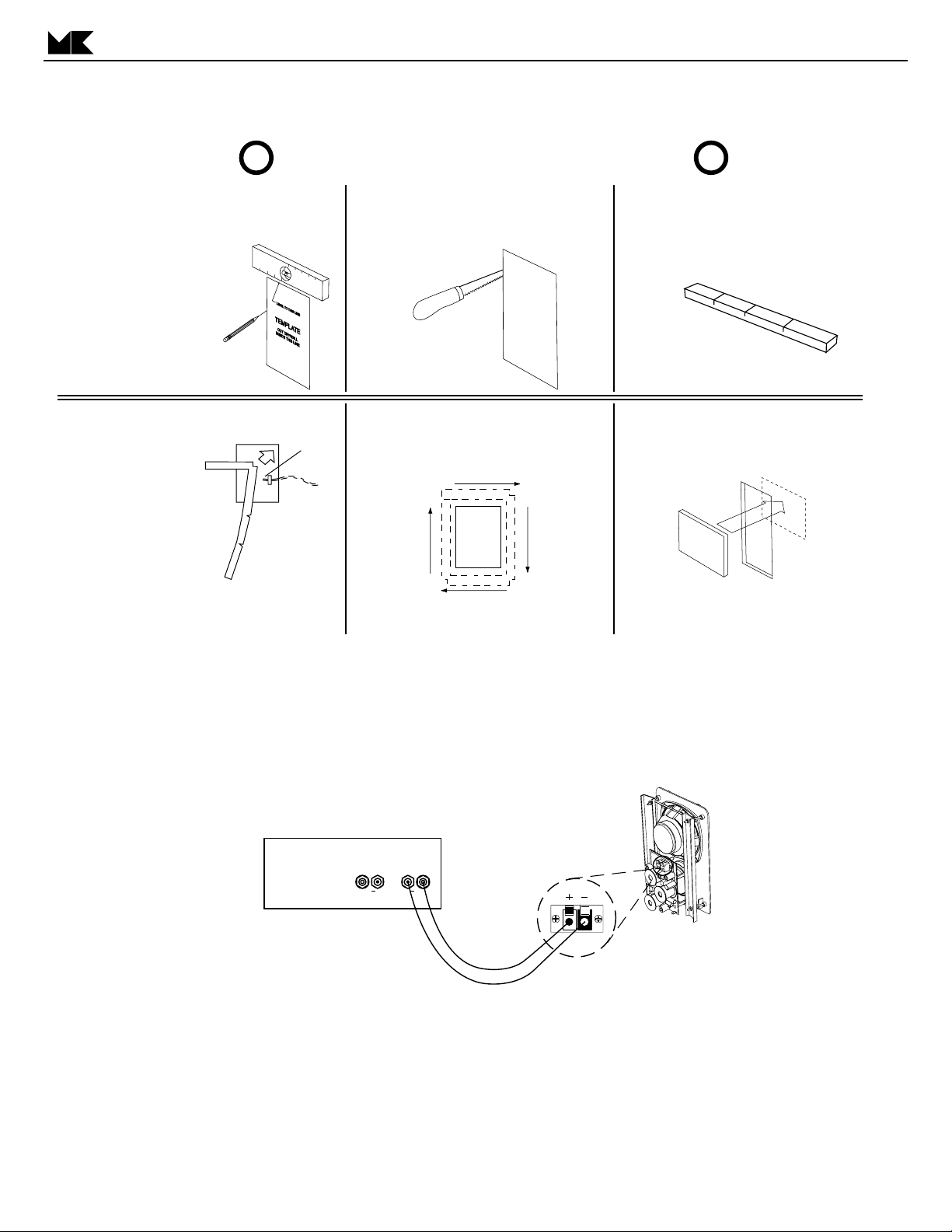
2. INSTALLATION INTO EXISTING WALLS
3. SPEAKER WIRING
The Positiv e (+) lead from your amplifier or receiv er should be connected to one of the RED (+) INPUT terminal, and the Negative
(-) lead from your amplifier or receiver should be connected to one BLACK (-) INPUT terminal.
4. SPEAKER WIRING FOR SW-85 AND SW-95 SPEAKERS ONLY
VARIATIONS OF SOUND (SW-85 and SW-95 only)
Your M&K SW-85 & SW-95 speakers reproduce sound with e xceptional tr ansient accuracy and a very wide dynamic range. They
will give you outstanding results with any high quality amplifier or receiver.
IMPORTANT! - MAKE SURE WALL ELECTRICITY IS
! !
TURNED OFF BEFORE STARTING INSTALLATION
1. ALL MODELS: Mark wall with template,
using a stud finder to maintain a 2" distance
from any stud. Make sure that you are clear
of any crossbraces in the
wall structure.
FOR STANDARD INSTALLATION
DRYW ALL THICKNESS CANNOT
EXCEED 1.25 INCHES.
FOR THICKER WALLS CALL
M&K SOUND.
4. SW-95, SW-50, SW-51 ONLY:
Tape the speaker wire to
the back wall so the
speaker
wire
end is within the
opening as shown.
5. Fold the first section of the foam strip and
insert the corner through the wall opening.
2. ALL MODELS: Cut opening precisely
with drywall saw, drywall router, etc.
Sand edges and clean debris from
installation area.
6. SW-95, SW-50, SW-51 ONLY:
Continue folding and inserting the rest of
the foam strip into the wall opening until
the foam frame is created.
7. Make sure that the frame is centered
within the opening
3. SW-95, SW-50, SW-51 ONLY:
Your speaker installation kit includes a foam
strip to fill in the wall space around the back
of your speaker. The foam strip has 1"deep
slits to allow bending it into a 4-sided frame.
NOTE: Be careful when bending and handling the
strip so that you do not rip it.
8. ALL MODELS: Mount the adhesive
backed foam pad in the wall approximately
five inches above the bottom of the cutout.
This puts the foam behind the woofer.
NOTE: Do not put any other acoustic filler
within the wall opening as it can interfere
with speaker mounting.
AMPLIFIER OR RECEIVER
LEFT RIGHT
+
+
Page 5
5
FRAMELESS IN-WALL SPEAKER
Howev er, getting the best tonal balance in any given room involves many variables. Therefore , the SW-85 and SW-95 speakers allow you to alter their tonal balance in order to get the ideal sound quality at your favorite listening location (where it counts!),
for the program and playback levels you are using—all by selecting the appropriate combination of input terminals to connect the
speakers to your amplifier.
The terminals are labeled EQUALIZED and NORMAL. The label is on the crossover printed circuit board. Both positions
have the same power handling capacity, but the NORMAL position plays the loudest, and works best with low powered amplifiers .
Bear in mind that the NORMAL terminal requires a higher setting of the subwoofer level. Conversely, if you switch to the
EQUALIZED terminal, the subwoofer level should be set lower.
We provide the multiple terminals because we cannot predict in advance exactly what response the speaker will produce in
your room. The choices available through the terminals, however, can allow you to create a virtually ideal response for your room
and program material. Hence, you should use the terminals that best balance the sound for your ears and y our room, so that you
get maximum enjoyment from your speakers.
MAXIMUM OUTPUT / NORMAL OUTPUT TERMINALS (SW-85 and SW-95 only)
EQUALIZED (Lower-Level Music Playback)
The EQUALIZED terminal gives you a response that is optimized for playback of music at moderate and background
music levels. It gives you a warm "musical" sound with a response tailored to the ear's hearing sensitivity at moderate
and low volume levels. This ter minal will produce the greatest perceived bass output, so it should be used when the
speaker is being played without a subwoofer. Very similar in character to the finest British-manufactured monitor
speakers, but with a significantly wider dynamic range, this speaker's characteristic is sometimes referred to as the
"English Sound."
NORMAL (Reference-Level/Film Playback)
The NORMAL terminal gives you a response that is optimized for playback of film soundtracks and playback of music at
It gives you a bright, "forward" sound with greater efficiency and a wider dynamic range with a slightly rising high
frequency characteristic, as compared to the EQUALIZED terminal.
This input is particularly useful for producing maximum sound power levels, especially with low-powered amplifiers. It is
recommended when the speakers are used as surround speakers, as its high frequency contour can improve the high
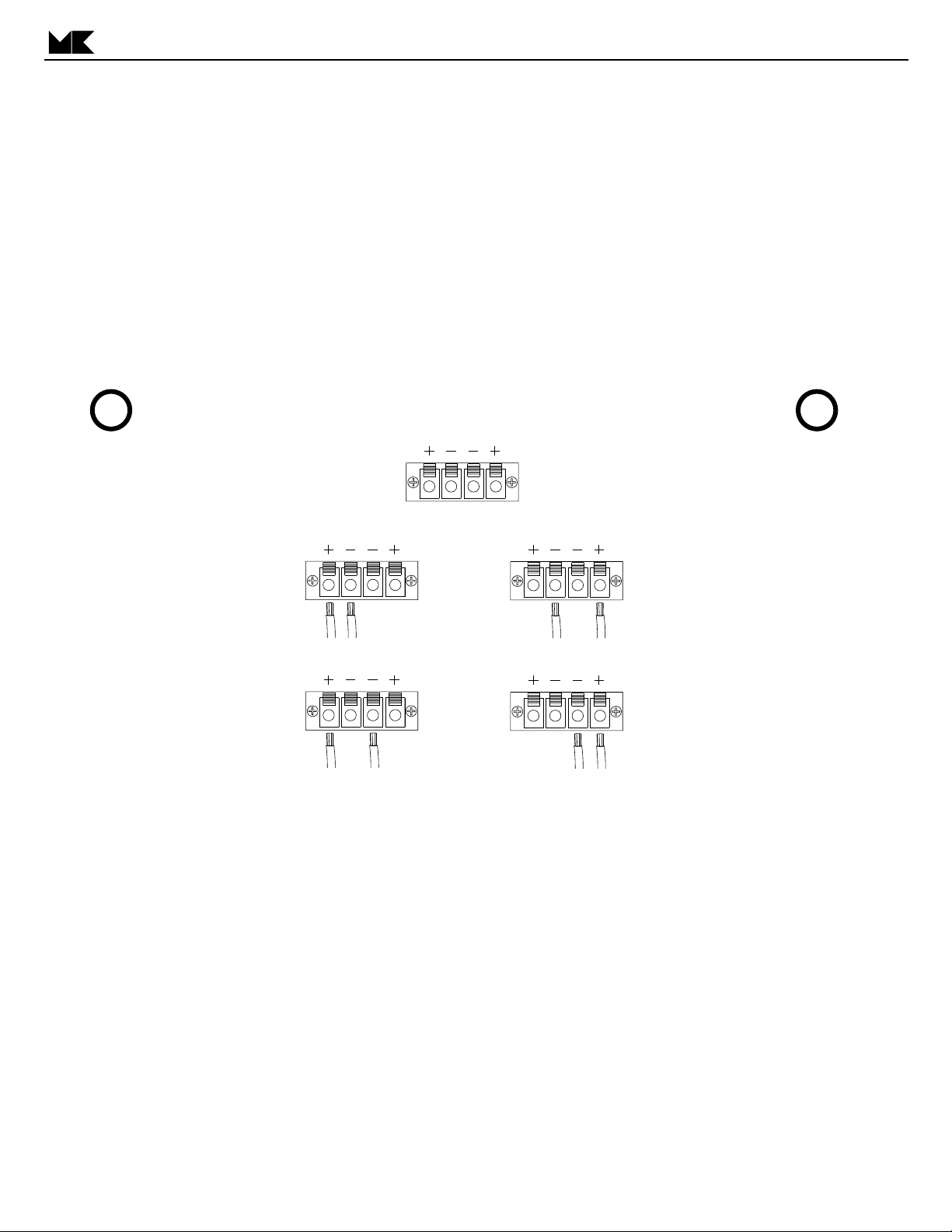
IMPORTANT! - MAKE SURE THAT YOU USE ONLY ONE RED (POSITIVE) AND ONLY ONE BLACK
! !
(NEGATIVE) CONNECTOR, OR YOU MAY CAUSE DAMAGE TO YOUR SPEAKER OR AMPLIFIER
NORMAL/NORMAL
NORMAL/BASS ROLLOFF
EQUALIZED/NORMAL
EQUALIZED/BASS ROLLOFF
Page 6
6
FRAMELESS IN-WALL SPEAKER
frequency response at the listeners' ears. It produces the flattest overall frequency response with your wall- or ceilingmounted SW speaker.This position is sometimes referred to as the "German" sound.
LOW CUT (HIGH PASS FILTER) / WIDE RANGE TERMINALS (SW-85 and SW-95 only)
BASS ROLL OFF
Your M&K SW series speaker has very high power handling for an architectural speaker. But it is possible to overdrive
the woofer with deep bass signals, especially when you are using a high powered amplifier. This is the reason for the
BASS ROLL OFF terminal. Using this ter minal introduces a built-in filter that reduces (rolls off) the speaker's bass
output below 80 Hz (at 6dB per octave). This can be helpful when you are using a separate subwoofer.
If you are not using a subwoofer, however, this filter will produce an audible reduction in bass output. Many listeners will
prefer the sound of the speaker without the filter. Therefore, for most systems, we recommend using the NORMAL
terminal. This gives you the natural roll off of the speaker and will give you the best sound quality in almost all cases.
NORMAL
As we say above, the NORMAL terminal gives you the natural roll off of the speaker without any additional reduction of
bass. If you do not have a subwoofer and are not using a high-powered amplifier to play the system at high volume
levels, we recommend that you use the NORMAL terminal.
If you have a separate electronic high-pass filter (such as the M&K BMC-MINI), always use the NORMAL terminal, as
you do not want to have both the separate and built in filters operating simultaneously. This also applies if your
amplifier or controller has built-in high-pass filters (such as THX-approved components and AC-3 units).
REMOTE SWITCHING OF VARIATIONS OF SOUND (SW-85 and SW-95 only)
If you run wire with multiple conductors to your speakers, y ou can s witch between the v arious choice of tonal quality by remote
control. You need a four-conductor wire to make all of the switching options available. You also need an amplifier switcher that
will allow you to choose to feed the amplifier's (+) output to one of two terminals and the amplifier's (-) output to one of two other
terminals.
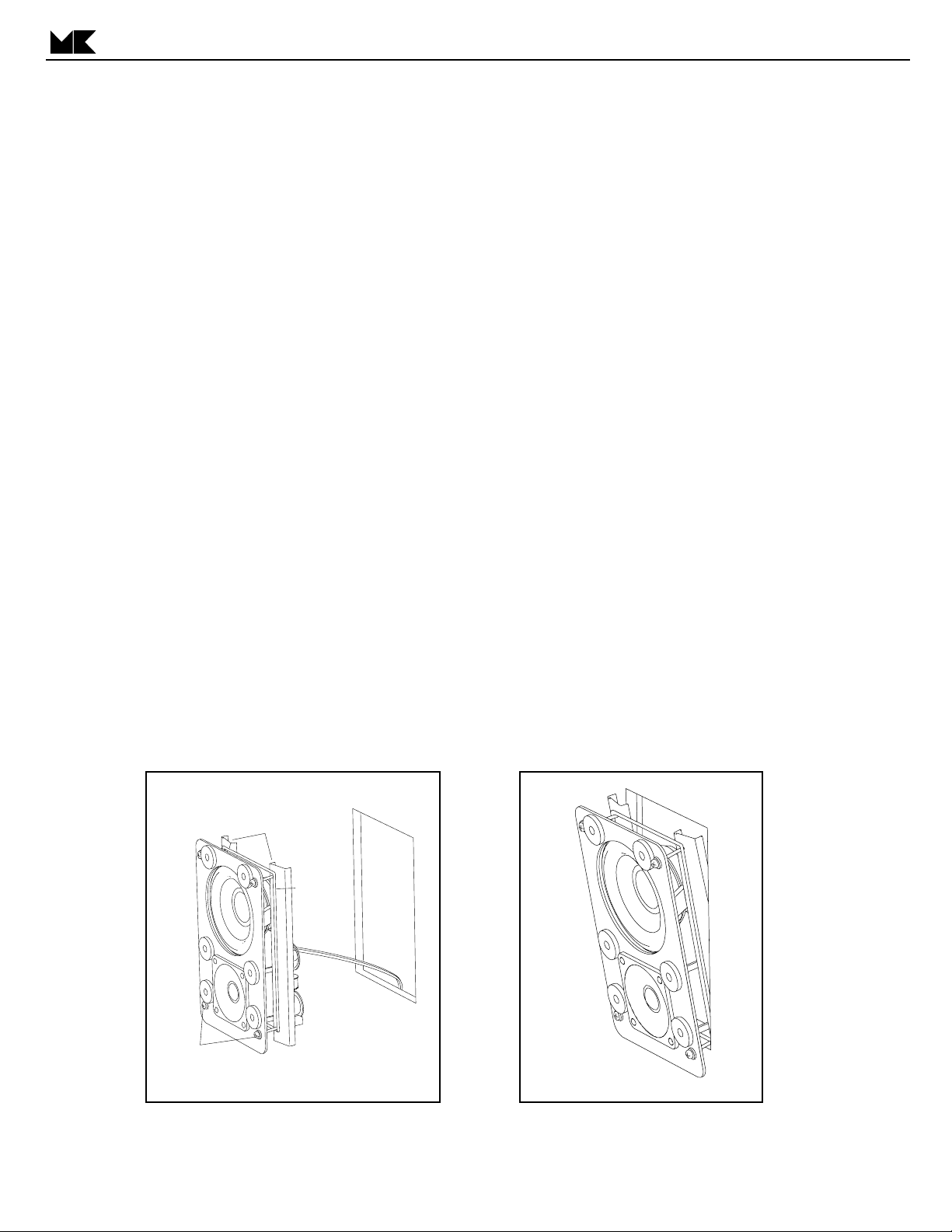
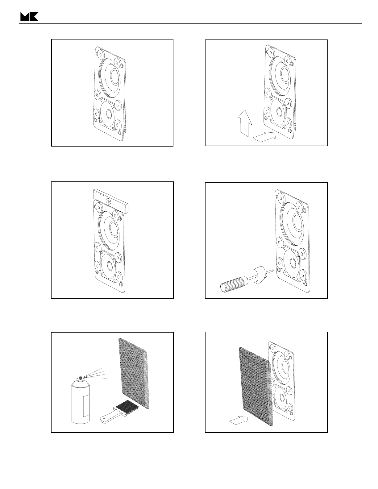
5. MOUNTING YOUR NEW SPEAKER IN THE WALL
NOTE:The speaker in the drawing may not match your speakers. It is shown as an example only.
mounting arms
elastic cord
mounting screws
10. Remove packing material and grille from
speaker. Do not remove the elastic cord! Make
sure that the mounting screws are flush with the
front baffle as shown.
11. Angle the speaker toward the wall and
slip the bottom portion of the mounting arms
into the wall opening.
Page 7
7
FRAMELESS IN-WALL SPEAKER
12. Tip the unit vertically and pass the top edge of
the mounting arms through the wall opening, allowing
the unit to rest on the bottom mounting screws.
14. Make sure that the baffle is level by checking
with a leveling device.
13. Raise the unit and press it toward the wall until it
rests on the metal flanges and is flush with the wall.
15. Tighten all mounting screws sequentially to light
resistance. Continue to tighten screws to an even
torque that will secure the baffle to the wall.
16. The grille can be painted with Latex paint to match
the wall color if desired. Make sure that the paint is
thin enough and applied carefully so that it does not
clog the openings on the grille.
17. Attach the grille. Make sure that the grille is
securely mounted on magnets by tapping on it's
surface. Remove and reposition the grille if necessary.
Page 8

8
FRAMELESS IN-WALL SPEAKER
If you have any questions about your speaker system, please contact your M&K dealer or call the M&K factory directly at
(818) 701-7010, from 8:30 AM to 5:00 PM Pacific Time, Monday through Friday. We will be happy to help you with any question.
Additional information may also be obtained on our web site www
.mksound.com or you may send us an e-mail to
suppor
6. SATELLITE AND SUBWOOFER PHASE TEST
When using a subwoofer with your SW -150, a phasing test m ust be perf ormed to insure good bass blending. This test insures
optimum sound in the critical bass frequencies where your Subwoofer and Main speakers overlap.
Play a familiar CD or DVD with steady, consistent bass content through your system. Listen carefully to the "mid-bass" region
of 75 - 125 Hz. This is the part of the spectrum where electric or str ing basses and drums predominate. Then reverse the phase
of either the subwoofer or BOTH Main speakers.
If your Subwoofer has a PHASE switch on its back panel, move it either from (+) to (—) or vice versa.
If your Subwoofer does not ha ve a PHASE switch, it takes a bit more work. You will have to change the Positive and Negative
speaker inputs on the back of BOTH Main speakers.
You can do this at the back of both Main speakers, or at the Subwoofer's TO SPEAKERS terminals, but never at both locations. The lead that was on the Positive (+) terminal should be switched to the Negative (—) terminal, and vice versa. When
switching speaker wires, take care to protect your amplifier. Make sure that the wires do not touch each other when you are making the switch. As a safety measure, we suggest that you turn the amplifier off before making the switch.
Now listen to the same musical passage as you did earlier, concentrating on the mid-bass region. If you hear less bass, the
original connection (or switch position) was correct. If you hear more bass, the new connection (or switch) is correct.
7. SPEAKER DAMAGE & HOW TO AVOID IT
An important factor to consider with any loudspeaker system is the potential for speak er damage. Even though your surround
speakers have extremely high power handling ability, they still can be damaged by relatively low powered amplifiers.
While very few M&K Satellites are actually returned for service, the vast majority of those returned are not for manufacturing
defects. Instead, they are returned because they have been overdriven, almost always because the amplifier or receiver used
was driven into clipping distortion. This damage is considered abuse, and is not necessarily covered under warranty.
This clipping distortion occurs when the demands of the music are greater than the amplifier's available power. It can occur
at 20 watts with a small amplifier, or at 400 watts with a large amplifier. Regardless, when this happens, the amplifier's output
waveform (which usually looks like a smooth arc) is "clipped" off, exhibiting a flat top instead of the arc.
This flat top contains multiples of the original amplified frequencies, sometimes at higher levels than the original signal itself.
For tweeters, this can be very damaging, as this distor tion is well above the audible range, where you will be unable to hear it,
and where the tweeter is more vulnerable to damage.
When an amplifier clips, its sound becomes harsh and grating, and a break-up is often audible in the bass frequencies. It will
become uncomfortable to listen to, compared to a slightly lower volume level. When you are listening at high volume levels, be
aware of the onset of clipping distortion, and turn the volume down slightly if the sound takes on the character described above.
When tone controls or equalizers are used to boost frequencies, the problem occurs much more rapidly. Even a small boost
of low or high frequencies can easily double the power requirement and lead to amplifier clipping at moderate levels. Therefore,
you should use your tone controls judiciously, avoiding extreme boosts of the bass and treble controls, especially when you are
listening at high volume levels.
The best way to avoid speaker damage is to use common sense. Use moderate boosts of tone controls or equalizers, at the
very most. Listen carefully for any harshness and break-up, especially at high volume levels, and turn down the volume when
needed. If you cannot get enough volume, you may need to consider a higher-pow ered amplifier. If you hav e an y questions about
this, please contact M&K, and we will be happy to discuss it with you fur ther.
Page 9
9
FRAMELESS IN-WALL SPEAKER
8. IF YOU NEED SERVICE
Contact your dealer or M&K with a complete description of the problem. Please have the unit's model and serial numbers (found on the back of the cabinet), date of purchase, and your dealer's name. You can call M&K between
8:30 AM and 5:00 PM Pacific Time, Monday through Friday, at (818) 71-7010. If you call outside these hours, leave
a message, and we will return your call. Alternatively, you may send us an e-mail to ser
DO NOT RETURN YOUR SPEAKERS TO THE FACTORY FOR
SERVICE WITHOUT OBTAINING PRIOR AUTHORIZATION.
9. M&K 10 YEAR WARRANTY
All M&K speakers (except f or subwoof ers) carry a ten year limited parts and labor warranty. This warranty is transferable to new owners. It does not cover abuse, misuse, repairs by unauthorized service stations, speakers without
serial numbers, and those damaged in shipping or by accident. If you have any questions about the warranty, please
contact M&K.
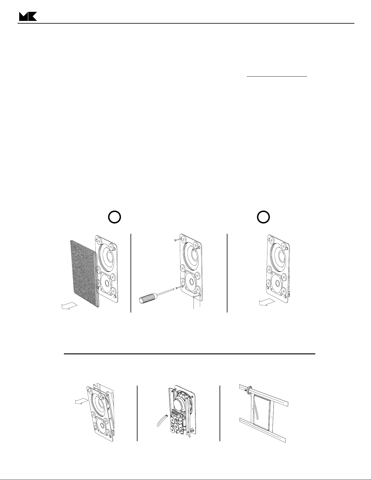
10. REMOVING THE SPEAKER FROM THE WALL
Follow these steps to remove your M&K in-wall speaker from the wall.
IMPORTANT! - MAKE SURE WALL ELECTRICITY IS
! !
TURNED OFF BEFORE REMOVING THE SPEAKER !
2
1. Remove the speaker grille.
IMPORTANT! - BE SURE THAT YOU SECURE THE LOOSE SPEAKER WIRES TO THE BRACKET OR
THE STUD OR THEY WILL BE LOST IN THE WALL!
2. While holding baffle, loosen screws
sequentially until two inches of screw is
exposed, or screw stops. If using a power
screwdriver, make sure that it is on a low
torque setting to avoid stripping.
3. Push the screws in until they are
flush with the front of the baffle.
32. Pull bottom of speaker slightly forward
until bottom screws rest on the drywall.
4. Pull top of speaker out
of the wall opening.
5. Disconnect wires
from crossover.
6. Attach loose wires to stud or bracket
Page 10
10
FRAMELESS IN-WALL SPEAKER
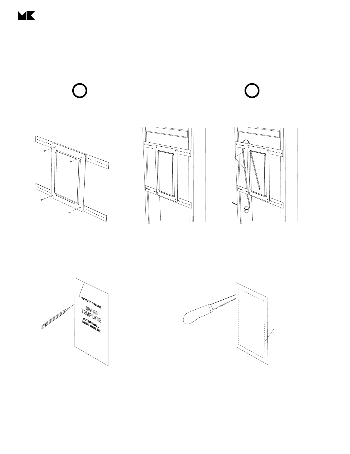
11. PRE-CONSTRUCTION BRACKET INSTALLATION
NOTE: This step is optional and applies to new construction only.
IMPORTANT! - MAKE SURE WALL ELECTRICITY IS
! !
TURNED OFF BEFORE STARTING INSTALLATION !
Note: Detailed Pre-Construction instructions are included with the Pre-Construction Bracket kit. The following
instructions are intended as an overview only.
staples
1. Attach the mounting strips to
the pre-construction bracket with
the included sheet metal screws.
4. Measure and mark the drywall with
the template and attach the drywall
to the stud wall.
2. Attach the bracket assembly
to the wall studs with screws or
nails (not included).
5. Rough cut the drywall opening to the inside
of the marked line making sure that you are
cutting inside the pre-construction bracket
opening. Continue to cut the opening using
the bracket flange as a guide. Slightly angle
the cut to the outside so that you can pull
the bracket flange through the drywall opening.
3. Run the speaker wire to the location
of the bracket. Secure the wire to one
of the studs using staples or U nails.
Make sure that the wire is clear of the
opening or it may be damaged when
the drywall is cut.
rough cut
Continue with the installation instructions
on page 4.
Page 11

FRAMELESS IN-WALL SPEAKER
11
12. SPECIFICATIONS
SW-95 & SW-62
IMPEDANCE: 4 ohms
RECOMMENDED POWER: amplifiers with between 25 and 200 watts continuous
MAXIMUM POWER: 200 watts RMS unclipped peaks
FREQUENCY RESPONSE: 70 Hz - 20 kHz ± 2 dB
SENSITIVITY (2.83 V @ 1m): 92dB
OVERALL DIMENSION (H x W): 12.75” x 9.75”
CUTOUT DIMENSION (H x W): 10.56” x 7.25”
WEIGHT: 10 lbs.
MOUNTING DEPTH: 3.67” (SW-95) 3.58” (SW-62)
SW-85 & SW-52
IMPEDANCE: 4 ohms
RECOMMENDED POWER: amplifiers with between 25 and 200 watts continuous
MAXIMUM POWER: 200 watts RMS unclipped peaks
FREQUENCY RESPONSE: 85 Hz - 20 kHz ± 2 dB
SENSITIVITY (2.83 V @ 1m): 88dB
OVERALL DIMENSION (H x W): 11” x 7.2”
CUTOUT DIMENSION (H x W): 9.4” x 6”
WEIGHT: 9 lbs.
MOUNTING DEPTH: 3.67”
SW-54
IMPEDANCE: 4 ohms
RECOMMENDED POWER: amplifiers with between 25 and 200 watts continuous
MAXIMUM POWER: 200 watts RMS unclipped peaks
FREQUENCY RESPONSE: 85 Hz - 20 kHz ± 2 dB
SENSITIVITY (2.83 V @ 1m): 88dB
OVERALL DIMENSION (H x W): 8.9” x 7.3”
CUTOUT DIMENSION (H x W): 7.68” x 5.77”
WEIGHT: 6 lbs.
MOUNTING DEPTH: 3.05”
SW-51
IMPEDANCE: 4 ohms
RECOMMENDED POWER: amplifiers with between 25 and 200 watts continuous
MAXIMUM POWER: 200 watts RMS unclipped peaks
FREQUENCY RESPONSE: 85 Hz - 20 kHz ± 2 dB
SENSITIVITY (2.83 V @ 1m): 88dB
OVERALL DIMENSION (H x W): 8.9” x 7.3”
CUTOUT DIMENSION (H x W): 7.68” x 5.77”
WEIGHT: 6 lbs.
MOUNTING DEPTH: 3.05”
SW-50
IMPEDANCE: 4 ohms
RECOMMENDED POWER: amplifiers with between 25 and 200 watts continuous
MAXIMUM POWER: 200 watts RMS unclipped peaks
FREQUENCY RESPONSE: 85 Hz - 20 kHz ± 2 dB
SENSITIVITY (2.83 V @ 1m): 88dB
OVERALL DIMENSION (H x W): 10.3” Diameter
CUTOUT DIMENSION (H x W): 7.68” x 5.77”
WEIGHT: 6 lbs.
MOUNTING DEPTH: 3.05”
Page 12

FRAMELESS IN-WALL SPEAKER
In-wall speaker manual
PN# 70071
08/29/02 rev. 2 pt/qrk
 Loading...