

MK Sound K-15, K-5, K-17 User Manual

K-17, K-15
K-7, K-5
Miller & Kreisel Sound, Inc.
9351 Deering Avenue
Chatsworth, CA 91311-5858 USA
(818) 701-7010 fax (818) 701-0369
www.mksound.com
©2002 Miller & Kreisel Sound, Inc.
satellite speaker
operation manual
TM

TABLE OF CONTENTS
1. INTRODUCTION............................................................................................3
2. PLACEMENT OF YOUR SPEAKERS.........................................................................3
3. USING THE FLUSH MOUNT HANGER BRACKETS.............................................3
4. SPEAKER HOOK-UP......................................................................................................4
5. OPTIMIZING SPEAKER PLACEMENT..........................................................................5
6. HOME THEATRE USAGE.............................................................................................7
CENTER CHANNEL.............................................................................................7
SURROUND CHANNEL.......................................................................................8
7. SATELLITE/SUBWOOFER PHASING TEST...............................................................9
8. SPEAKER DAMAGE & HOW TO AVOID IT..............................................................10
9. M&K 5.1 MULTICHANNEL & PRO-LOGIC SYSTEM SETUP GUIDE...........................11
10. IF YOU NEED SERVICE OR SET-UP ASSISTANCE...................................................13
11. M&K 10 YEAR WARRANTY...........................................................................................13
12. CABINET MAINTENANCE..............................................................................................13
13. USE WITH M&K BRACKETS.......................................................................................13
14. SPECIFICATIONS..................................................................................................14
DIAGRAMS
FIGURE 1 BRACKET & SPEAKER ORIENTATION..............................................................4
FIGURE 2 SPEAKER WIRING......................................................................................5
FIGURE 3 SEPARATION BETWEEN LEFT & RIGHT SPEAKERS..................................6
FIGURE 4 SURROUND SPEAKER PLACEMENT (ONE ROW OF LISTENERS)...........8
FIGURE 5 SURROUND SPEAKER PLACEMENT (REAR WALL)......................................8
FIGURE 6 MULTIPLE SURROUND SPEAKER PLACEMENT...............................................9
K-15/K-5 WALL MOUNTINGBRACKET TEMPLATE.........................................15
K-17/K-7 WALL MOUNTINGBRACKET TEMPLATE.........................................16
K-SERIES SATELLITE SPEAKER
2
Please record the following information for your records:
Serial Number:
Date of Purchase:
Dealer Name:
Dealer Address:
City/State/Zip:
Country:
Invoice Number:

1. INTRODUCTION
Congratulations! Your new M&K speaker system will give y ou y ears of unmatched enjoyment and e xcitement while
listening to your favorite musical and audio/video sources.
We encourage you to read this owner’s manual, as there is a great deal of information provided here to help you
achieve the best possible performance.
If you have any questions about your speaker system, please contact your M&K dealer or call the M&K factory
directly at (818) 701-7010, from 8:30 AM to 5:00 PM Pacific Time, Monday through Friday.We will be happy to help
you with any question, no matter how simple or comple x it may be.Additional information may also be obtained on our
web site: www
.mksound.com or you may send us an e-mail at support@mksound.com.
This manual gives you basic hook-up instructions first, followed by more detailed technical, installation, and
service information.
2. PLACEMENT OF YOUR SPEAKERS
Your M&K speakers can be installed in a wide variety of locations. Their compact size gives you great flexibility
in installation. They can be placed on stands, shelves, or bookcases, or more permanently mounted using brackets,
through direct attachment to a wall, or with a ceiling suspension system.
If you want to mount your speakers permanently using wood screws, their cabinet thickness is 1/2". Do not use
longer screws, as you may damage the internally mounted crossover.
You can place the left and r ight speakers virtually anywhere in the room, but certain locations are better than
others. In general, locate them away from obstructions that would interfere with the direct path from the speakers to
your ears (such as walls, furniture, lighting, plants, etc.). Center channel speakers should be located close to the
television screen (see Home Theater Usage on page 8). Your speakers will sound better when they are around ear
height, or when angled towards your listening location. They sound better when they are not sitting on the floor.
For more detailed information on placement of your speakers, see Section 5 (page 6).
Your speakers are magnetically shielded. This means that you can locate them close to a television set or even
directly on top of the set.
In some rare instances, a small amount of residual magnetism at a specific angle to your TV set may cause
a slight geometric or color distortion of the picture on your television set. If you do get this distortion, try moving
the speaker slightly until the distortion is reduced or disappears. Then turn the set off and wait 10 minutes
before turning it back on to trigger the set's degaussing circuitry. If you cannot solve any magnetic problems,
contact the M&K factory.
3. USING THE FLUSH MOUNT HANGER BRACKETS
FLUSH-MOUNT WALL HANGER BRACKETS
Your speakers come with a flush-mount wall bracket that can be attached to each cabinet. There are pilot holes
for mounting the brackets on the back baffle of the speaker. Also included are the matching brackets that attach
directly to the wall, as well as all necessary mounting screws and drywall inserts.
In order to use these brackets, see the enclosed template on pages 15 & 16
and follow these instructions.
NOTE:When the speaker is mounted above the listeners’ heads, make
certain that the tweeter on the front baffle is at the bottom. See FIGURE 1.
3
K-SERIES SATELLITE SPEAKER
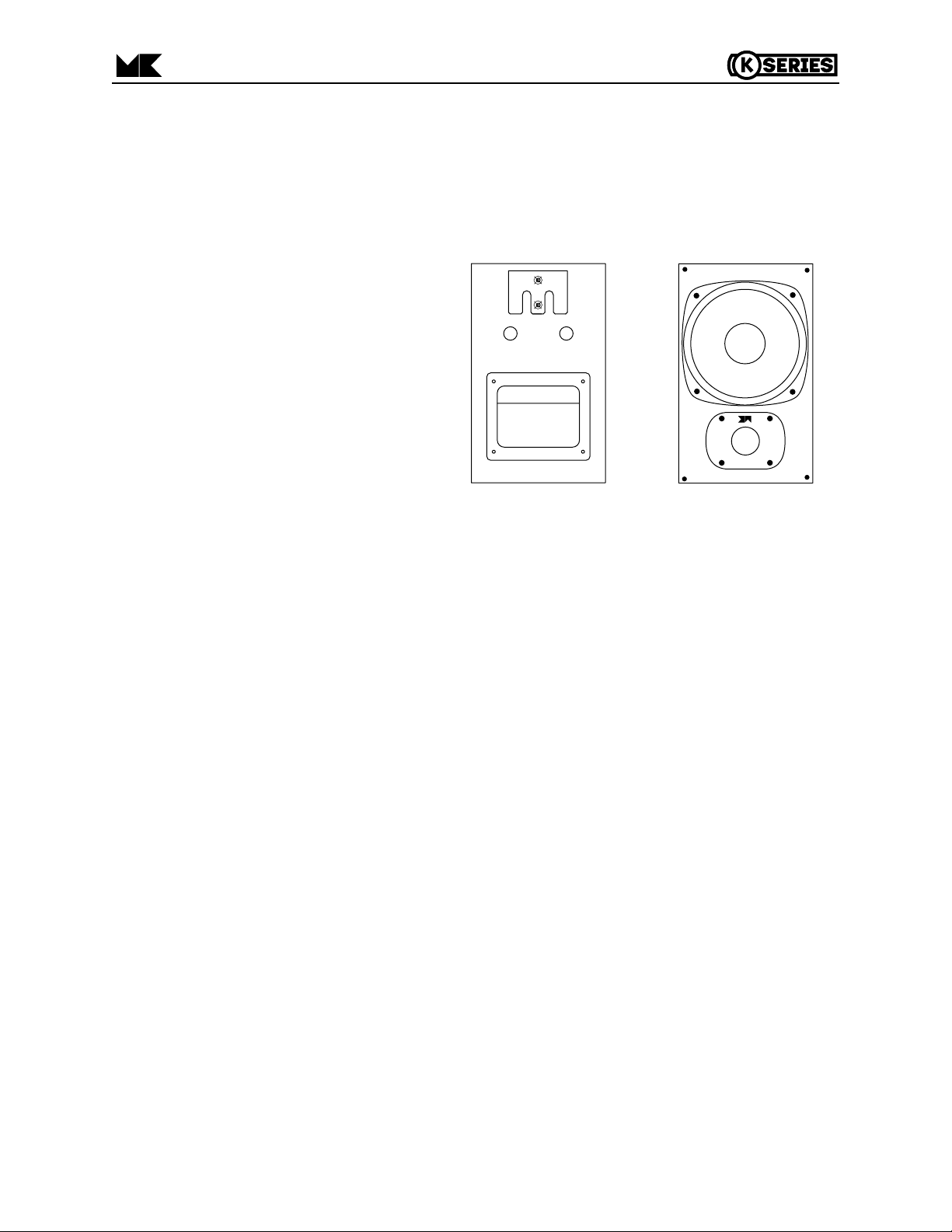
Attach the brackets to the speaker using the enclosed 3/4" wood screws. Use the pilot holes at the top center of
the back baffle of the cabinet. Either of the matching brackets can be attached to the speaker. The bracket that
attaches to the speaker must point down, and the bracket that attaches to the wall must point up. In both cases, the
face with the printing must face out.
Then determine where you will locate your
speakers. See Section 5 for guidelines on where
to locate the speakers. Then, using the template
sheet enclosed, mark holes on the wall where the
brackets will be permanently mounted. Ideally,
one set of these holes should go into a wall stud,
to give you the greatest strength.
First, locate the center of the stud. Tape the
four corners of the template sheet to the wall in
the location you have selected, using a carpenter's level to make sure the line marked "LEVEL
TEMPLATE TO THIS LINE" is lev el. The template
sheet has locations marked for the two mounting
holes needed to attach the wall bracket to the
wall.
Once you are absolutely certain that you
have the correct location, you are ready to drill the
pilot holes. Go ahead and drill right through the
paper template into the wall. Re-check your
measurements (especially making sure the holes
will be level) at least once before drilling.
WARNING: IT IS POSSIBLE THAT
ELECTRICAL WIRING MAY BE LOCATED
BEHIND THE WALL IN THE LOCA TION
THAT YOU HAVE SELECTED. BE
EXTREMELY CAREFUL ANY TIME
YOU DRILL INTO A WALL.
If you are mounting the bracket to a wall stud, drill two 3/32" holes per bracket. Remember that the wallboard
material is 1/2" or 5/8" inches thick, and you will drill through this before meeting the stud. If you are mounting the
bracket to drywall with the plastic anchors, drill two 1/8" pilot holes per bracket, insert the plastic wall anchors into the
1/8" pilot holes and drive the anchor into place using a Philips screwdriver until they are flush with the wall. Once all
holes have been drilled, remove the template from the wall.
Once the holes are drilled, place one bracket against the wall, making sure that the "tongue" (the portion that will
engage the bracket on the speaker cabinet) is facing away from the wall and pointing up. Using the two #6 - 1 3/4"
wood screws provided, fasten this bracket to the wall. BE VERY CAREFUL. DO NOT FORCE THE PLASTIC
ANCHORS THROUGH THE WALL OR OVERTIGHTEN THE SCREWS.
That's it! All that is left for you to do is attach the speaker wire to the input terminals (Section 4), and, from the
top, gently slide the speaker into place against the wall.
4. SPEAKER HOOK-UP
Please follow these instructions carefully, to avoid any possible damage to the speakers or your amplifier, and to
get the best possible sound.
The sound quality of your speakers can be affected by the type of speaker wire that you use to connect them.
While it is possible to use speaker wire as thin as 22 gauge to hook your speak ers up , we recommend using the largest
diameter wire that you can. This means a minimum of 18 gauge wire. Over 10 feet, you should use 16 gauge, and
for more than 30 feet, we recommend using 14 gauge or heavier. The smaller the number, the thicker the wire.
(A) Position the bracket on the speaker as pictured
when the speaker is to be located above the listeners’
ear level.
(B) Proper orientation of the front of the speaker when
it’s located above the listeners’ ear level. Notice the
tweeter is located towards the bottom of the baffle.
A
B
REAR
FRONT
4
K-SERIES SATELLITE SPEAKER
FIGURE 1
-
+
There are a very wide variety of premium speaker cables available from a number of specialist manufacturers.
We do not endorse any specific brand of premium cable, but we do recommend using as high quality a cable as fits
your budget. Using better quality cables will improve the sound of your Satellites.
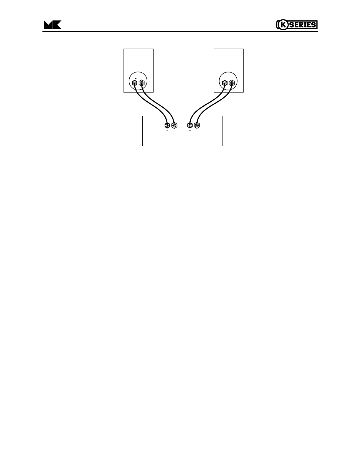
HOOKUP
For each speaker, connect the Positive (+) lead from your amplifier or receiver to the RED (+) INPUT terminal
and connect the Negative (-) lead from your amplifier or receiver to the BLACK (-) INPUT terminal. See Figure 2.
5. OPTIMIZING SPEAKER PLACEMENT
The sound quality produced by your speakers can be enhanced by careful attention to their placement. While we
understand that you may not redesign your room to accommodate your speakers, coming as close as possible to the
ideal placement will give you much better sound.
The left, right and center channel speakers can be oriented either horizontally or vertically. All speakers can be
angled with the optional ST-BT5 wall bracket (Section 13, page 14).
Three factors are important in getting the best sound. They are:
A. Height (or angle).
B. Location away from room walls or reflecting surfaces.
C. Separation between Left and Right speakers.
A. HEIGHT (OR ANGLE)
Your M&K speakers will always deliver sound superior to conventional speakers, regardless of where you locate
them. However, because they are designed for very fast and accurate transient response, they achieve even better
sound quality, and the flattest frequency response when properly oriented relative to your ear.
Ideally, the tweeters should be at the same height from the floor as your ears, when you are sitting in your main
listening position.
If you have the speakers mounted above or below this height, they sound their best when you angle the
speakers so that the tweeters are aimed at your ears when you are in the main listening position.
NOTE:When the speaker is mounted above the listeners’heads, make certain that the tweeter on the front
baffle is at the bottom.
FIGURE 2
5
K-SERIES SATELLITE SPEAKER
+
SATELLITE SPEAKERS
+
RIGHT LEFT
AMPLIFIER OR RECEIVER
+
+
 Loading...