

Page 1
BE-65 Inwall Bass Extender Installation Instructions
TABLE OF CONTENTS
Page 1...........Component Overview
Page 2...........Connecting Wires to Speakers
Page 3...........Remote Hookup
Page 4...........Installation Method
Page 5...........Acoustic Frame
Page 6...........Mounting Speaker in Wall
Page 7...........Mounting Continued
Page 8...........Pre-Construction Installation
Page 9...........Removing Speaker
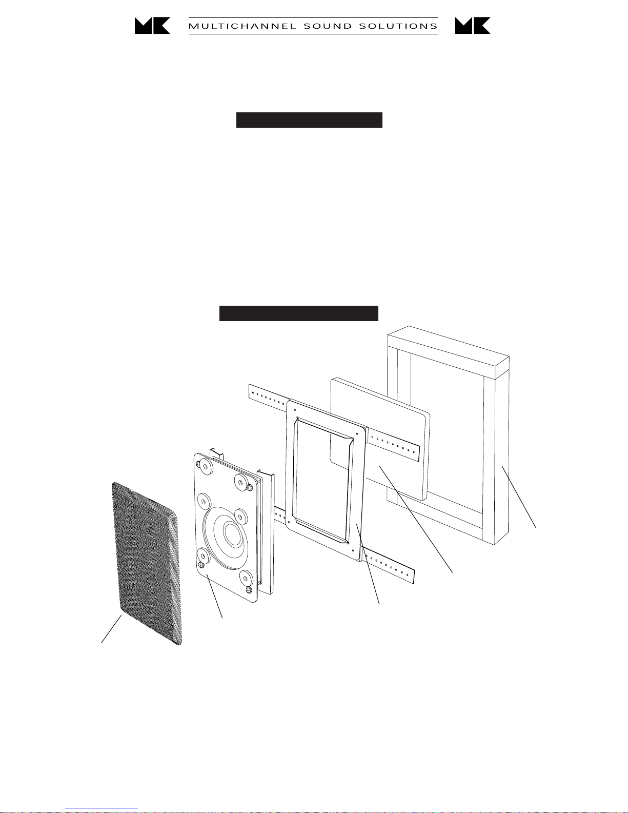
COMPONENT OVERVIEW
Inwall Speaker Assembly
Speaker Grille
THESE ARE THE MAJOR COMPONENTS OF YOUR NEW SPEAKER SYSTEM
Foam
Foam Dampening Pad
Pre-Construction Assembly
(Optional: order from your dealer as part number SPRE-95)
(1)
Page 2

Standard Hookup
The BE-65 must be connected between your amplifier and your SW-85 or SW-95 speaker. There are four wiring
diagrams below. Follow the diagram labeled with the tonal balance you have selected for your SW-85 or SW-95
speaker. For more information, see your SW-85/SW-95 instructions.
Hookup
For each channel, run one pair of wires from the amplifier to each BE-65. Attach the wires to BE-65’s "Normal
Input" (the right hand pair of terminals on the BE-65).
Make sure that you connect wires between the Red (+) terminal on the amplifier and the Red (+) terminal on the
BE-65, and between the Black (-) terminal on the amplifier and the Black (-) terminal on the BE-65.
Then run another pair of wires from the terminal strip at the top of the BE-65 circuit board up to that channel’s
SW-85 or SW-95’s input terminals. Attach the wires to the right hand pair of terminals on the BE-65 (the Red
terminal labeled Equalized; and the Black terminal labeled Rolloff). Use the terminals on the SW-85/SW-95 that
will give you the desired tonal balance.
See your SW-85/SW-95 instructions for more information on their available tonal balances.
RED EQUALIZED
Wiring to operate your
SW-95/SW-85 in
Bass Rolloff, EQ Mode.
BLACK NORMAL -
RED NORMAL +
BLACK BASS ROLLOFF
SATELLITE XOVER BOARD
Wiring to operate your
SW-95/SW-85 in
BLACK NORMAL -
RED NORMAL +
Normal Bass, EQ Mode.
RED EQUALIZED
BLACK BASS ROLLOFF
SATELLITE XOVER BOARD
Wiring to operate your
SW-95/SW-85 in
Normal Bass, Hi Eff Mode
BLACK NORMAL -
RED NORMAL +
REMOTE INPUT NORMAL INPUT
+ -
- +
AMPLIFIER
BLACK NORMAL -
RED NORMAL +
BLACK NORMAL -
RED NORMAL +
+ -
SPEAKER WIRE
RED EQUALIZED
BLACK BASS ROLLOFF
RED EQUALIZED
BLACK BASS ROLLOFF
SATELLITE XOVER BOARD
SPEAKER WIRE
RED EQUALIZED
BLACK BASS ROLLOFF
SW-BE65 XOVER BOARD
SW-BE65 XOVER BOARD
Wiring to operate your
SW-95/SW-85 in
Bass Rolloff, Hi Eff Mode
BLACK NORMAL -
RED NORMAL +
REMOTE INPUT NORMAL INPUT
+ -
- +
AMPLIFIER
BLACK NORMAL -
RED NORMAL +
BLACK NORMAL -
RED NORMAL +
+ -
RED EQUALIZED
BLACK BASS ROLLOFF
RED EQUALIZED
BLACK BASS ROLLOFF
RED EQUALIZED
BLACK BASS ROLLOFF
SPEAKER WIRE
SPEAKER WIRE
SW-BE65 XOVER BOARD
SATELLITE XOVER BOARD
SW-BE65 XOVER BOARD
REMOTE INPUT NORMAL INPUT
+ -
+ -
- +
AMPLIFIER
(2)
REMOTE INPUT NORMAL INPUT
+ -
+ -
- +
AMPLIFIER
Page 3
RED EQUALIZED
BLACK BASS ROLLOFF
BLACK NORMAL -
RED NORMAL +
SATELLITE XOVER BOARD
SPEAKER WIRE
BE65 XOVER BOARD
AMPLIFIER
RED EQUALIZED
BLACK BASS ROLLOFF
BLACK NORMAL -
RED NORMAL +
REMOTE INPUT NORMAL INPUT
+ -
+ -
- +
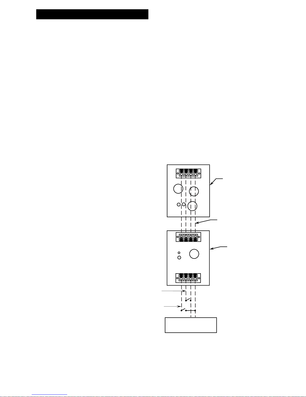
Optional Remote Hookup and Usage
(3)
SWITCH TO THIS CONNECTION
FOR SW-85/SW-95 "NORMAL"
MODE
SWITCH TO THIS CONNECTION
FOR SW-85/SW-95 "HIGH EFFICIENCY"
MODE
BE-65 HOOKUP WITH
OPTIONAL REMOTE SWITCHER
Allows the user to select
SW-85/SW-95 Tonal Characteristic.
(Requires 2 sets of speaker wires)
If you have a remote amplifier switcher, you can switch between tonal balances on your SW-85 or SW-95
speakers. See your SW-85 or SW-95 manual for details on wiring and the effect the use of the terminals
has on the speakers' sound.
When using a BE-65, you must connect two pairs of wires between the BE-65 and the SW-85/SW-95.
See the diagram below for details. If you have any questions about connecting your BE-65, please
contact your M&K dealer or the factory at (310) 204-2854.
Page 4
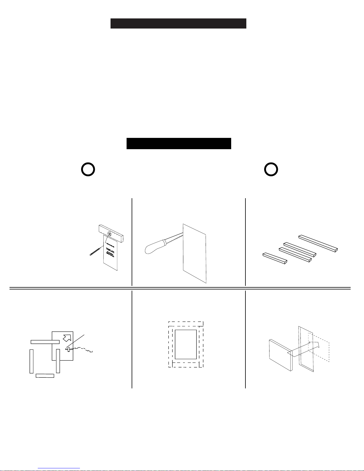
DETERMINE INSTALLATION METHOD
If you are installing your new speaker into existing walls, please see the section on post
construction installation below.
If you are installing your speakers into walls that are new construction, use the Pre-Construction
Bracket Instructions that are included with your Pre-Construction Bracket Kit SPRE95; also see
page 7.
Post Construction Installation
IMPORTANT! - MAKE SURE WALL ELECTRICITY IS
! !
TURNED OFF BEFORE STARTING INSTALLATION
1. Mark wall with template, using a stud finder
to maintain a 2" distance from any stud. Make
sure that you are clear of any crossbraces in
the wall structure.
FOR STANDARD INSTALLATION
DRYWALL THICKNESS CANNOT
EXCEED 1.25 INCHES.
FOR THICKER WALLS CALL
M&K SOUND.
For best performance, the BE-65
should be located as close to the floor and
corner of the room as possible. In most
situations, the cut-out should be 4
1/4
" above the floor.
4. Tape speaker wire to the back wall so the
end is within the opening as shown.
5. Place the first section of the foam strip and
insert the corner through the wall opening.
speaker
wire
2. Cut opening precisely with drywall
saw, drywall router, etc. Sand edges
and clean debris from installation area.
6. Continue to insert the remaining foam
strips into the wall opening until the foam
frame is created. (See pg. 5)
3. BE-65 Model includes 4 foam pieces
to be placed in the wall space around
the speaker.
Be careful when bending and handling
the foam so that you do not rip it.
8. Mount the adhesive backed foam
pad in the wall behind the woofer.
7. Make sure that the frame is centered
within the opening.
(4)
Note: Do not put any other acoustic
filler within the wall opening as it can
interfere with speaker mounting.
Page 5
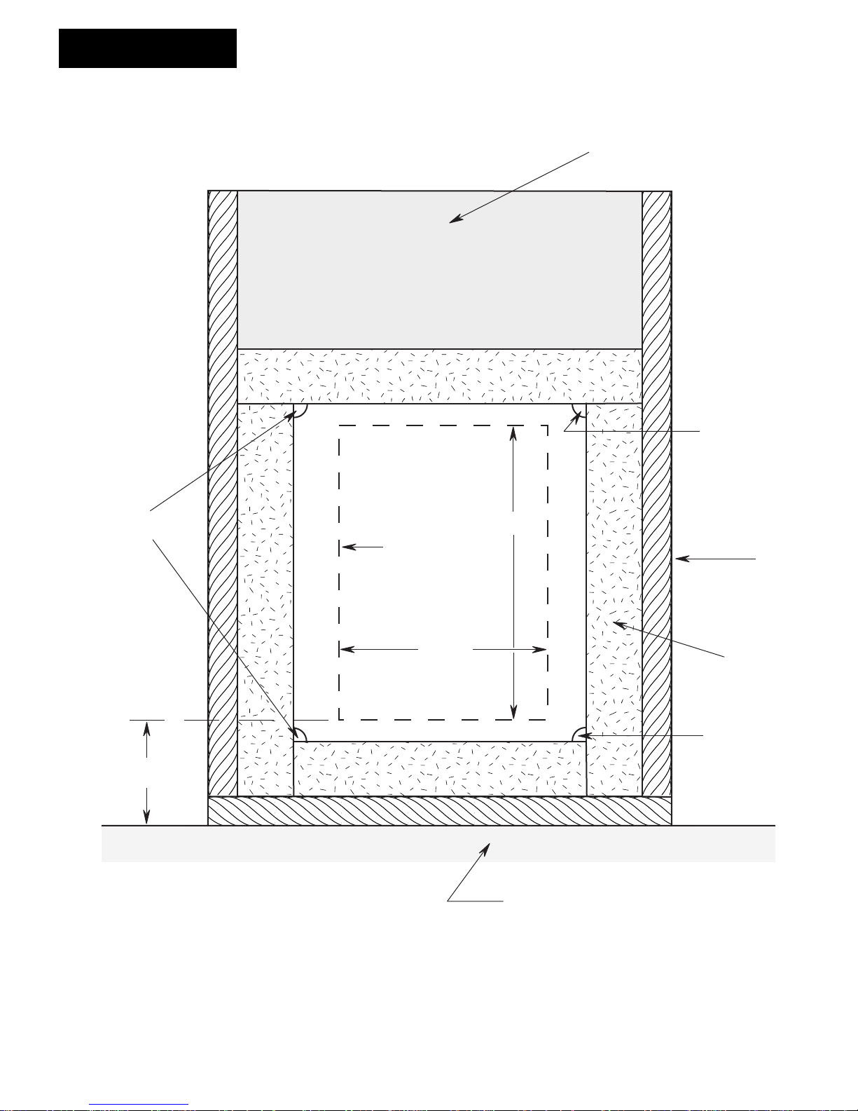
Acoustic Frame
Vanfill
Apply sealant
Apply sealant
4 1/4"
Cut out
7
7/16"
10
3/4"
Wall Stud
Foam
Apply sealant
Floor
Apply silicon based sealant to the foam frame joints.
It is very important to form an airtight enclosure.
(5)
Page 6
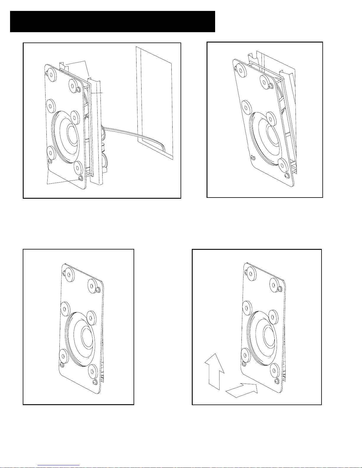
Mounting Your New Speaker in the Wall
mounting arms
elastic cord
mounting screws
(4 total)
9. Remove packing material and grille from speaker.
Do not remove the elastic cord! Make sure that the
mounting screws are flush with the front baffle as shown.
10. Angle the speaker toward the wall and
slip the bottom portion of the mounting arms
into the wall opening.
11. Tip the unit vertically and pass the top
edge of the mounting arms through the
wall opening, allowing the unit to rest on
the bottom mounting screws.
12. Raise the unit and press it toward the wall
until it rests on the metal flanges and is flush with
the wall.
(6)
Page 7
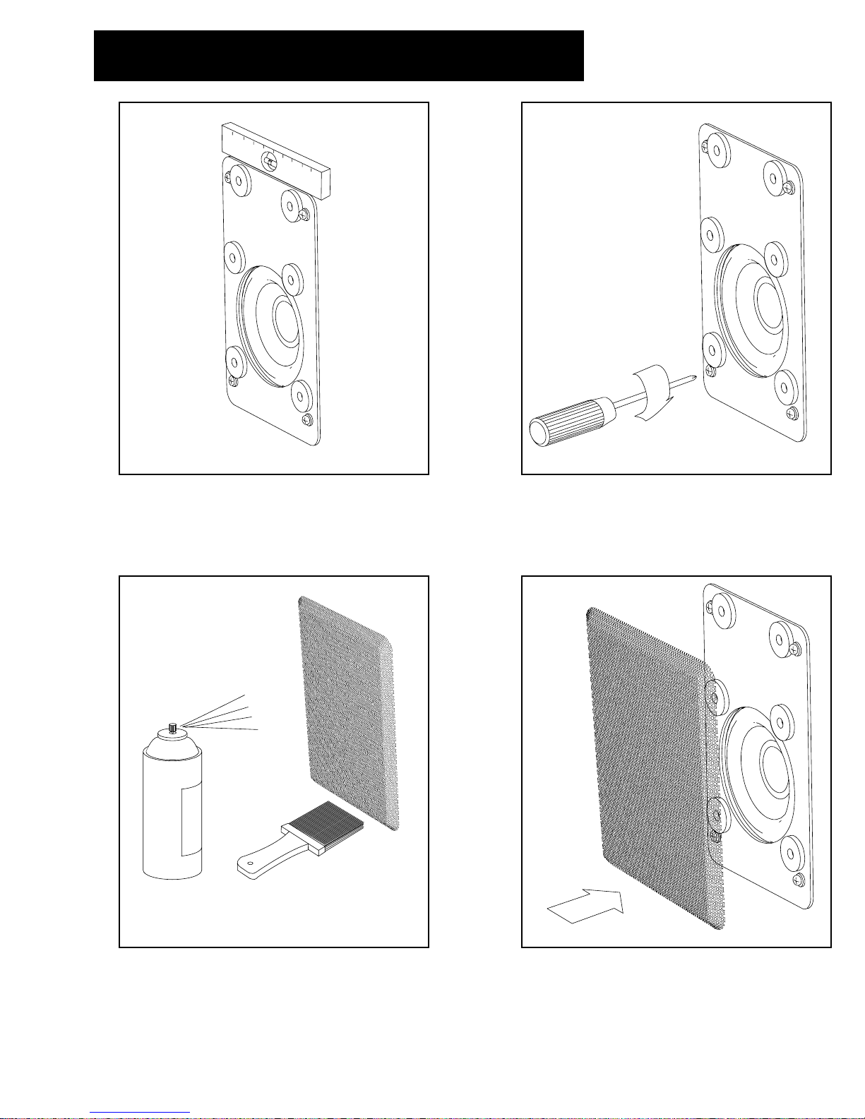
Mounting continued
13. Make sure that the baffle is level by checking
with a leveling device.
14. Tighten all mounting screws sequentially
to light resistance. Continue to tighten screws
to an even torque that will secure the baffle
to the wall.
15. The grille can be painted with Latex paint to
match the wall color if desired. Make sure that
the paint is thin enough and applied carefully so
that it does not clog the openings on the grille.
16. Attach the grille. Make sure that the grille is
securely mounted on magnets by tapping
on it's surface. Remove the grille and
reposition magnets if necessary.
(7)
Page 8
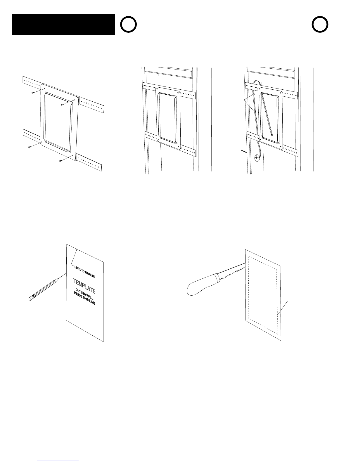
Pre-Construction Installation
Note: Detailed Pre-Construction instructions
are included with the Pre-Construction
Bracket kit SPRE95. The following instructions
are intended as an overview only.
! !
IMPORTANT! - MAKE SURE WALL ELECTRICITY IS
TURNED OFF BEFORE STARTING INSTALLATION !
staples
1. Attach the mounting strips to
the pre-construction bracket with
the included sheet metal screws.
2. Attach the bracket assembly
to the wall studs with screws or
nails (not included).
3. Run the speaker wire to the location
of the bracket. Secure the wire to one
of the studs using staples or U nails.
Make sure that the wire is clear of the
opening or it may be damaged when
the drywall is cut.
rough cut
4. Measure and mark the drywall with
the template and attach the drywall
to the stud wall.
5. Rough cut the drywall opening to the inside
of the marked line making sure that you are
cutting inside the pre-construction bracket
opening. Continue to cut the opening using
the bracket flange as a guide. Slightly angle
the cut to the outside so that you can pull
the bracket flange through the drywall opening.
(8)
Page 9
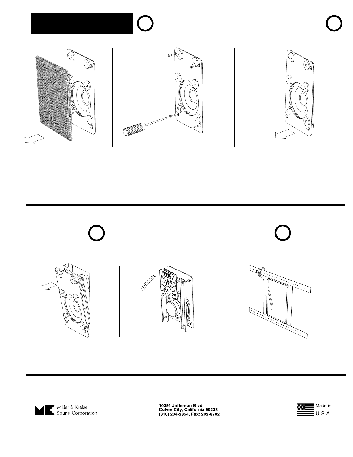
Removing the Speaker
IMPORTANT! - MAKE SURE WALL ELECTRICITY IS
! !
TURNED OFF BEFORE REMOVING THE SPEAKER !
2
1. Remove the speaker grille.
2. While holding baffle, loosen screws
sequentially until two inches of screw is
exposed, or screw stops. If using a power
screwdriver, make sure that it is on a low
torque setting to avoid stripping.
3. Push the screws in until they are
flush with the front of the baffle.
4. Pull bottom of speaker slightly forward
until bottom screws rest on the drywall.
IMPORTANT! - BE SURE THAT YOU SECURE THE
LOOSE SPEAKER WIRES TO THE BRACKET OR
!
THE STUD OR THEY WILL BE LOST IN THE WALL!
!
5. Pull top of speaker out
of the wall opening.
6. Disconnect wires
from crossover.
(9)
7. Attach loose wires to stud or bracket
 Loading...