

MKS Spectra Vision 2000-P User Manual

SP102006.103
March 2013
Vision 2000-P
Manual
MKS Instruments UK Ltd
V2000-P Hardware Manual – SP102006.103 March 2013
1

As part of our continuous product improvement policy, we are always pleased to receive your comments and
suggestions about how we should develop our product range. We believe that the manual is an important part of
the product and would welcome your feedback particularly relating to any omissions or inaccuracies you may
discover.
This equipment is manufactured by:
MKS Instruments UK Ltd. – Spectra Products
3 – 4 Cowley Way
Crewe
Cheshire
CW1 6AG
United Kingdom
Tel: +44 (0)1270 250150
You can obtain UK support for this product from the following location:
MKS Instruments UK Ltd. – Spectra Products
3 – 4 Cowley Way
Crewe
Cheshire
CW1 6AG
United Kingdom
Tel: +44 (0)1270 250150
In the USA:
MKS Instruments, Spectra™ Products
70 Rio Robles Drive
San Jose
CA 95134
Toll Free: 800-428-9401
Tel: 408-750-0300
Or to find a local agent, please visit:
http://www.mksinst.com/service/servicehome.aspx
MKS Products provided subject to the US Export Regulations.
Diversion or transfer contrary to U.S. law is prohibited.
Windows is a registered trademark of the Microsoft Corporation and is fully recognised.
Swagelok is a registered trademark of the Swagelok Company and is fully recognised.
MKS Instruments UK Ltd
V2000-P Hardware Manual – SP102006.103 March 2013
2

MKS Instruments UK Ltd
V2000-P Hardware Manual – SP102006.103 March 2013
3

Additional Installation Maintenance and Operating Instructions
WARNING-DANGEROUS VOLTAGES EXIST INSIDE THE
EQUIPMENT
In order to comply with European regulations, the following procedures must be followed:
Installation
The installation procedures given in the operating and technical manuals must be followed, in addition to these
instructions:
The mains power cable must conform to local regulations and must have a protective earth (PE)
conductor securely connected to the power plug protective earth contact.
Only cables supplied with the equipment may be used for interconnections. If extension cables are
required to obtain a greater separation between control unit and RF head, or if longer serial
communications cables are required, they must be supplied by MKS Instruments UK Ltd.
Cables attached to all other ancillary signal and control ports must have a length of less than 3 metres. If
greater length is required, MKS Instruments UK Ltd must be contacted for technical guidance on
possible EMC and safety issues.
The vacuum system on which the analyser/RF head is mounted must be earthed, to a protective earth,
preferably to the same protective earth as the control unit.
Operation
The equipment is not authorised for use as a critical component in a life support or safety critical system without
the express written approval of MKS Instruments UK Ltd.
All instructions given in the operating manual must be followed.
Adjustments are strictly limited to those accessible from the control panel and computer keyboard and only when
running software supplied by MKS Instruments UK Ltd.
Maintenance
Maintenance functions must only be carried out by competent persons.
During the warranty period, faulty equipment must be returned to MKS Instruments UK Ltd., unless special
arrangements are made.
There are no user replaceable parts in the electronic equipment. Certain components are EMC and safety critical
and must not be substituted. Replacement parts are available from MKS Instruments UK Ltd.
Equipment enclosures embody certain special fastening and bonding devices that affect EMC and safety
performance. These must be correctly re-fitted after servicing.
MKS Instruments UK Ltd
V2000-P Hardware Manual – SP102006.103 March 2013
4

Table of Contents
Additional Installation Maintenance and Operating Instructions .................................................................. 3
Installation .................................................................................................................... 4
Operation ................................................................................................................... 4
Maintenance .............................................................................................................. 4
Table of Contents ......................................................................................................... 5
Health & Safety ............................................................................................................ 6
Warning Symbols ....................................................................................................... 7
Fuses .......................................................................................................................... 7
Electrical Connections ................................................................................................ 7
Installation................................................................................................................... 8
Initial checks .............................................................................................................. 8
Dimensions ................................................................................................................ 9
System Components ................................................................................................ 10
Vacuum system installation ..................................................................................... 11
RGA vacuum chamber overview ...................................................................... 11
Main chamber installation ............................................................................... 12
Connecting the backing pump ......................................................................... 12
Heater jacket .................................................................................................... 12
Microvision 2 installation ................................................................................. 12
Electrical installation ................................................................................................ 13
Electrical specification ..................................................................................... 13
Equipment rack ................................................................................................ 13
Interconnecting cables ..................................................................................... 13
Mains power .................................................................................................... 13
RCV Connections .............................................................................................. 14
System Box Connections .................................................................................. 14
Connecting to the process tool (VacOK) .................................................................. 15
PC Connection .......................................................................................................... 15
Operation ................................................................................................................. 16
Overview .......................................................................................................... 16
Start up ............................................................................................................ 17
Leak checking ................................................................................................... 18
Heating and Baking .......................................................................................... 19
System shut down procedure .......................................................................... 20
Maintenance.............................................................................................................. 21
Operating pressure .......................................................................................... 21
Accessing the orifice disk ................................................................................. 21
Refitting the inlet flange .................................................................................. 21
Replacing the orifice ................................................................................................ 22
Orifice Disk Tools ............................................................................................. 22
Fitting the Tool Guide ...................................................................................... 23
Removing the Orifice Disk ................................................................................ 23
Fitting a new Orifice Disk ................................................................................. 24
Re-assembling the Inlet Flange ........................................................................ 25
Vision 2000-P electronics ................................................................................. 26
Diaphragm pump maintenance ....................................................................... 27
Turbo pump maintenance ............................................................................... 27
Mass spec maintenance ........................................................................................... 28
Removing the analyser ..................................................................................... 28
Re-fitting the analyser ...................................................................................... 28
Returning Your Equipment ...................................................................................... 29
Support Contact Numbers ............................................................................... 29
Health and safety clearance form .................................................................... 29
MKS Instruments UK Ltd
V2000-P Hardware Manual – SP102006.103 March 2013
5

Health & Safety
WARNING
This section of the manual contains important safety information.
Please read it carefully.
WARNING
WARNING boxes are used where failure to observe the instructions
could result in personal injury or death.
CAUTION
CAUTION boxes are used where failure to observe the instructions
could result in damage to the equipment or associated equipment.
Important safety information is highlighted by the use of WARNING and CAUTION boxes. The use of these
boxes is described below:
Instructions in CAUTION and WARNING boxes MUST be observed.
MKS Instruments accepts no liability for any injury or damage resulting from a failure to observe instructions in
CAUTION or WARNING boxes.
MKS Instruments UK Ltd
V2000-P Hardware Manual – SP102006.103 March 2013
6

Warning Symbols
Warning!
Danger of an electric shock.
Warning!
Danger of personal injury or damage to the unit. Refer
to manual for instruction
Warning!
Hot surface.
PE (Protective Earth)
All equipment external to the RVC must be earthed at
this point.
Various warning labels and symbols may be attached to the instrument their general use is explained below.
Fuses
The Vision 2000-P systems must be powered down and disconnected from the mains supply before changing
any fuses.
See the RVC2 User Manual for the fuse locations and values.
Electrical Connections
The Vision 2000-P must be powered down and isolated from the mains power supply before any electrical
connections are made.
On the rear panel of the Microvision2 there are no hazardous voltages on any of the ports (electrical connectors).
Connections must not be made that may place hazardous voltages or currents on these ports. MKS Instruments
must be consulted before any non-MKS Instruments cables or accessories are connected to these ports. Consult
the relevant manual for detailed descriptions of these connectors.
If you are unclear about any of the safety information contained in this section of the manual please contact your
local MKS Instruments facility before proceeding.
MKS Instruments UK Ltd
V2000-P Hardware Manual – SP102006.103 March 2013
7

Installation
CAUTION
There may be minor differences between one Vision 2000-P
system and another.
The Vision 2000-P is a self contained RGA system for sampling directly from PVD process chambers. It consists
of four main parts:
The RGA vacuum chamber that bolts directly on to the process chamber.
The equipment sub-rack housing an RVC2 Vacuum Controller
The interconnecting cables.
The operating PC.
The RGA vacuum chamber contains the quadrupole residual gas analyser with a differentially pumped PVD
source, a high conductance isolating valve, a turbomolecular pump, and the sampling orifice interface with
optional pressure reduction. This assembly is surrounded by an electrical heating jacket. A bracket fitted to the
turbo pump acts as a securing point for the cable trunking.
The backing pump is a dry diaphragm pump and a stainless steel foreline connects it to the turbo pump.
A 19inch sub rack houses the Remote Vacuum Controller (RVC2) and cables running between the sub rack and
the RGA vacuum chamber are fitted into trunking to give additional protection.
There are small differences between Vision 2000-P systems, these variations are usually due to the type of
process tool to which the Vision 2000-P is to be fitted, the type of process to be monitored and the pressure
regime from which the system will be sampling.
The design variations are purely to give the user the best possible system to meet the needs of the application.
This manual covers all variations of Vision 2000-P. The shipment report will detail your particular system and you
should refer to this when the manual gives details of options.
Initial checks
When you receive the equipment carefully check each item before removing the packaging to ensure that no
physical damage has occurred during shipment. Also check that all the boxes have been received by checking
against the packing slip.
If there has been obvious damage during shipment or if there are items listed on the packing slip as shipped
which have not arrived, immediately contact your local MKS Spectra facility or sales/service representative.
Carefully unpack the various parts of your Vision 2000-P system. Again, check for any signs of damage.
Find the shipment report and check for any missing items. Keep the shipment report safe, this is an important
document and you will need to refer to it later.
We suggest you keep the packaging material until the system is up and running as this seems to dramatically
reduce the chances of something needing to be returned!
Most insurance claims for shipment damage must be placed within 7 days from the date of delivery - in
WRITING. So, don’t delay Check It Out!
You are now ready to assembly the Vision 2000-P system.
MKS Instruments UK Ltd
V2000-P Hardware Manual – SP102006.103 March 2013
8
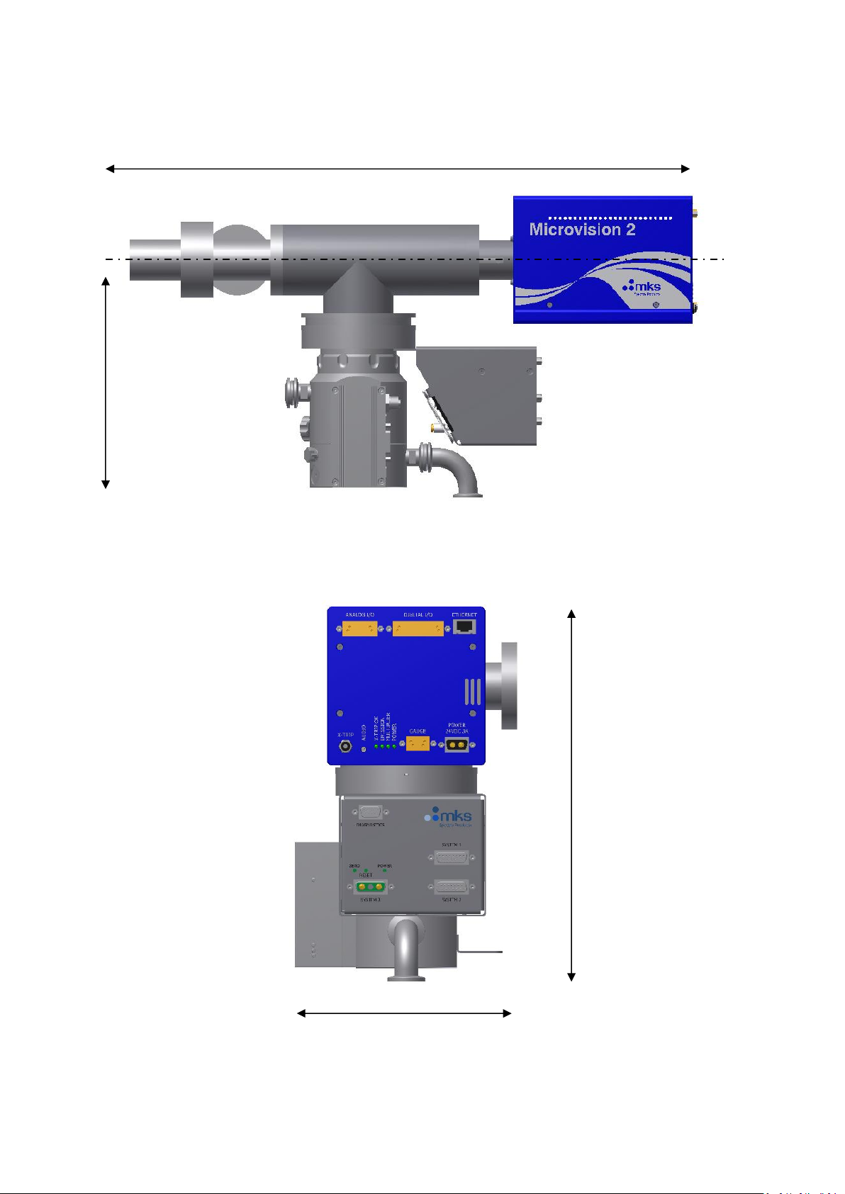
Dimensions
562mm
225mm
290mm
179mm
MKS Instruments UK Ltd
V2000-P Hardware Manual – SP102006.103 March 2013
9
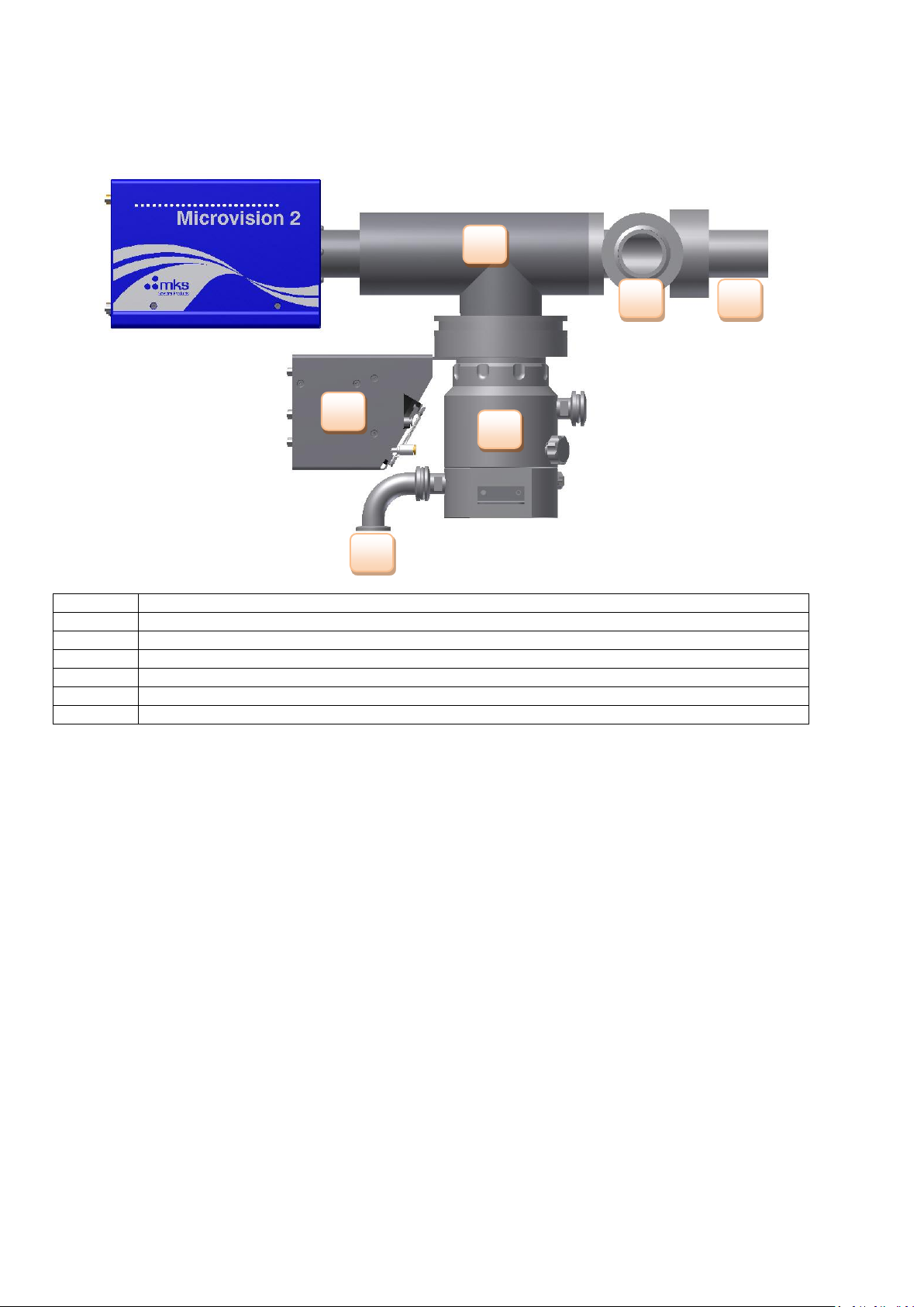
System Components
Item Ref
Description
1
RGA Chamber
2
Chamber Mounting Flange
3
Isolation Valve
4
System Interface Module (LM108)
5
Turbo Molecular Pump
6
Foreline Port
1 2 3
4
5
6
MKS Instruments UK Ltd
V2000-P Hardware Manual – SP102006.103 March 2013
10
 Loading...