

MKS nPC PCA0, nPC PC90, nPC PC99, nPC P99A Instruction Manual

TM
MKS Type πPC
Digital Pressure Controller
Instruction Manual
PCA & P99A
Ninety Industrial Way
Wilmington
MA 01887
Main: 978.284.4000
Fax: 978.284.4999
www.mksinst.com
1003195-001
Revision A, 3/08
Instruction Manual

WARRANTY
Type πPCTM Equipment
MKS Instruments, Inc. (MKS) warrants that for one year from the date of shipment the
equipment described above (the “equipment”) m anufactured by MKS shall be free from
defects in materials and workmanship and will correctly perform all date-related
operations, including without limitation accepting data entry, sequencing, sorting,
comparing, and reporting, regardless of the date the operation is performed or the date
involved in the operation, provided that, if the equipment exchanges data or is otherwise
used with equipment, software, or other products of others, such products of others
themselves correctly perform all date-related operations and store and transmit dates and
date-related data in a format compatible with MKS equipment. THIS WARRANTY IS
MKS’ SOLE WARRANTY CONCERNING DATE-RELATED OPERATIONS.
For the period commencing with the date of shipment of this equipment and ending one
year later, MKS will, at its option, either repair or replace any part which is defective in
materials or workmanship or with respect to the date-related operations warranty without
charge to the purchaser. The foregoing shall const itute the exclusive and sole remedy of
the purchaser for any breach by MKS of this warranty.
The purchaser, before returning any equipment covered by this warranty, which is
asserted to be defective by the purchaser, shall make specific written arrangements with
respect to the responsibility for shipping the equipment and handling any other inci dental
charges with the MKS sales representative or distributor from which the equipment was
purchased or, in the case of a direct purc hase from MKS, with the MKS home office in
Wilmington, Massachusetts, USA.
This warranty does not apply to any equipment which has not been installed and used in
accordance with the specifications recommended by MKS for the proper and normal use
of the equipment. MKS shall not be liable under any circumstances for indirect, special,
consequential, or incidental damages in connection with, or arising out of, the sale,
performance, or use of the equipment covered by this warranty.
MKS recommends that all MKS pressure and flow products be calibrated periodically
(typically every 6 to 12 months) to ensure accurate readings. When a product is returned
to MKS for this periodic re-c alibration it is considered normal preventative maintenance
not covered by any warranty.
THIS WARRANTY IS IN LIEU OF ALL OTHER RELEVANT WARRANTIES,
EXPRESSED OR IMPLIED, INCLUDING THE IMPLIED WARRANTY OF
MERCHANTABILITY AND THE IMPLIED WARRANTY OF FITNESS FOR A
PARTICULAR PURPOSE, AND ANY WARRANTY AGAINST INFRINGEMENT OF ANY
PATENT.
3-08 1003195-001

MKS Type πPC
1003195-001
Rev A, 3/08
TM
PCA & P99A
Digital Pressure Controller
Instruction Manual

Copyright © 2006 by MKS Instruments, Inc.
All rights reserved. No part of this work may be reproduced or transmitted in any form or by any means,
electronic or mechanical, including photocopying and recording, or by any information storage or retrieval
system, except as may be expressly permitted in writing by MKS Instruments, Inc.
Printed in the United States of America
®
Baratron
DeviceNet™ is a trademark of Open DeviceNet Vendor Association, Inc., Coral Springs, FL
Swagelok
Elgiloy
Inconel
and Mass-Flo® are registered trademarks of MKS Instruments, Inc., Andover, MA
®
and VCR® are registered trademarks of Swagelok Marketing Company, Solon, OH
®
is a registered trademark of Elgiloy Company.
®
and Incoloy® are registered trademarks of Inco Alloys International, Inc, Huntington, WV.
Protected under the following U. S. Patents: No. 5,461,913, 6,810,308, 7,000,465, or International Patents and
Patents pending.

Table of Contents
Table of Contents
List of Figures................................................................................................................................................... iii
List of Tables......................................................................................................................................................v
List of References............................................................................................................................................ vii
Pressure Transducer Safety Information ........................................................................................................1
Symbols Used in This Instruction Manual ....................................................................................................................1
Symbols Found on the Unit........................................................................................................................................... 1
Safety Procedures and Precautions................................................................................................................................ 1
Sicherheitshinweise für den Druckmeßumformer..........................................................................................3
In dieser Betriebsanleitung vorkommende Symbole.....................................................................................................3
Erklärung der am Gerät angebrachten Symbole............................................................................................................ 3
Sicherheitsvorschriften und Vorsichtsmaßnahmen .......................................................................................................3
Informations relatives à la sécurité concernant le transducteur de pression...............................................5
Symboles utilisés dans ce manuel d'utilisation.............................................................................................................. 5
Symboles figurant sur l'unité.........................................................................................................................................5
Mesures de sécurité et précautions................................................................................................................................ 5
Medidas de seguridad del transductor de presión..........................................................................................7
Símbolos usados en este manual de instrucciones......................................................................................................... 7
Símbolos hallados en la unidad..................................................................................................................................... 7
Procedimientos y precauciones de seguridad ................................................................................................................7
Chapter One: General Information ................................................................................................................9
Introduction ...................................................................................................................................................................9
How This Manual is Organized................................................................................................................................... 11
Customer Support........................................................................................................................................................ 12
Chapter Two: Installation and Configuration .............................................................................................13
Unpacking the πPC......................................................................................................................................................13
Product Location and Requirements............................................................................................................................14
Dimensions.................................................................................................................................................................. 15
Device Information (Labels, Display, C ommunication, Mounting, Leak Integrity).................................................... 22
Installation and Startup Procedure...............................................................................................................................27
Chapter Three: Ethernet Interface Setup and Configuration....................................................................31
Step 1: Install the Java™ Plugin (for single IP address) .............................................................................................31
Step 2: Setup Network for Communication Through Ethernet ...................................................................................32
Chapter Four: Embedded Web-Based GUI and Diagnostics.....................................................................41
Logging On To Your πPC........................................................................................................................................... 41
Monitor Mode..............................................................................................................................................................41
Setup Mode..................................................................................................................................................................46
Chapter Five: Overview .................................................................................................................................57
General Information ....................................................................................................................................................57
How the πPC Pressure Controller Works....................................................................................................................59
Tuning the πPC Pressure Controller............................................................................................................................61
i

Table of Contents
Operation of the πPC PC99 Model with Gases other than Nitrogen (Multi Gas)........................................................67
Versions of the πPC (Electrical Interface Related, i.e. Pinouts, cables, etc.) ..............................................................68
Interface Cables for Analog I/O ..................................................................................................................................71
Overview of the Analog πPC Operation......................................................................................................................73
Overview of πPC DeviceNet Digital Operation..........................................................................................................75
DeviceNet Protocol......................................................................................................................................................76
Overview of πPC RS-485 Digital Operation...............................................................................................................77
RS-485 Protocol ..........................................................................................................................................................77
Chapter Six: Maintenance............................................................................................................................. 79
General Information ....................................................................................................................................................79
Zero Adjustment..........................................................................................................................................................79
Chapter Seven: Troubleshooting .................................................................................................................. 85
Troubleshooting Chart.................................................................................................................................................85
Appendix A: Product Specifications for the PC90 Model ..........................................................................91
Physical Specifications................................................................................................................................................91
Performance Specifications .........................................................................................................................................91
Environmental Specifications......................................................................................................................................92
Mechanical Specifications..........................................................................................................................................92
Electrical Specifications .............................................................................................................................................92
Appendix B: Model Code Explanation for the PC90 Model ...................................................................... 95
Model Code Description..............................................................................................................................................95
Appendix C: Product Specifications for the PC99 Model ..........................................................................99
Physical Specifications................................................................................................................................................99
Performance Specifications .........................................................................................................................................99
Environmental Specifications....................................................................................................................................100
Mechanical Specifications........................................................................................................................................100
Electrical Specifications ...........................................................................................................................................101
Appendix D: Model Code Explanation for the PC99 Model....................................................................105
Model Code Description............................................................................................................................................105
Appendix E: Valve Orifice Selection ..........................................................................................................109
General Information ..................................................................................................................................................109
How to Verify the Orifice Selection..........................................................................................................................110
ii

List of Figures
List of Figures
Figure 1: 4-VCR Front View – DeviceNet .......................................................................................................15
Figure 2: 4-VCR Front View – 9-Pin D RS-485...............................................................................................16
Figure 3: 4-VCR Front View – 15-Pin D Analog.............................................................................................16
Figure 4: 4-VCR Left and Right Side Views – DeviceNet...............................................................................17
Figure 5: 4-VCR Left and Right Side Views – 9-Pin D RS-485 ......................................................................17
Figure 6: 4-VCR Left and Right Side Views – 15-Pin D Analog.....................................................................18
Figure 7: 4-VCR Top View (15-Pin D Analog Shown) ...................................................................................18
Figure 8: 4-VCR Bottom View.........................................................................................................................18
Figure 9: C or W Seal Front View – DeviceNet ...............................................................................................19
Figure 10: C or W Seal Front View – 9-Pin D RS-485 .....................................................................................19
Figure 11: C or W Seal Front View – 15-Pin D Analog....................................................................................20
Figure 12: C or W Seal Left and Right Views – DeviceNet..............................................................................20
Figure 13: C or W Seal Left and Right Side Views – 9-Pin D RS-485 .............................................................21
Figure 14: C or W Seal Left and Right Side Views – 15-Pin D Analog............................................................21
Figure 15: C and W Seal Top View (DeviceNet Shown) ..................................................................................21
Figure 16: C and W Seal Bottom View .............................................................................................................22
Figure 17: Labels for the πPC (PC99 and PC90)...............................................................................................22
Figure 18: Push Button Display Readouts .........................................................................................................23
Figure 19: Embedded GUI, Device Page in Monitor Mode (DeviceNet PC90 shown) ....................................42
Figure 20: Embedded GUI, Device Page in Monitor Mode (DeviceNet PC99 shown) ....................................42
Figure 21: Embedded GUI, Plot Page in Monitor Mode (PC90 shown) ...........................................................44
Figure 22: Embedded GUI, Diagnostics Page (PC99 shown) ...........................................................................45
Figure 23: Embedded GUI, Configuration Page in Monitor Mode (DeviceNet πPC shown)...........................46
Figure 24: Embedded GUI, Device Page in Setup Mode (DeviceNet PC90 shown) ........................................47
Figure 25: Embedded GUI, Device Page in Setup Mode (DeviceNet PC99 shown) ........................................48
Figure 26a: Embedded GUI, Multi Gas, Creating A New Gas Instance (PC99 only).......................................48
Figure 25b: Embedded GUI, Multi Range, Changing the Full Scale Flow Range (PC99 only) .......................49
Figure 27: Embedded GUI, Plot Page in Setup Mode (DeviceNet PC90 shown) .............................................50
Figure 28: Embedded GUI, Plot Page in Setup Mode (Analog)........................................................................50
Figure 29: Embedded GUI, Configuration Page in Setup Mode (DeviceNet PC99 shown) .............................51
Figure 30: Embedded GUI, Configuration Page in Setup Mode (Analog PC99 shown)...................................51
Figure 31: Embedded GUI, Optional PC Page in Setup Mode (Analog πPC Only) .........................................53
Figure 32: Embedded GUI, Plot Page with Enabled Optional Input (Analog PC99 Shown)............................54
Figure 33: Embedded GUI, DNet Settings Page in Setup Mode (PC99 shown) ...............................................55
Figure 34: πPC Controller in Downstream Control Position (PC90 or PC99)..................................................59
Figure 35: πPC Controller in Upstream Control Position (PC90 only).............................................................60
Figure 36: Effects of the Proportional Control ..................................................................................................61
Figure 37: Effects of the Integral Control..........................................................................................................62
Figure 38: Controller Response with Initial Kp and Ki term values..................................................................64
iii

List of Figures
Figure 39: Controller Response with New Kp and Ki term values ...................................................................65
Figure 40: Controller Response with New Kp and Ki term values ...................................................................66
Figure 41: DeviceNet Connector Pin Diagram.................................................................................................. 70
Figure 42: Orifice Selection Graph .................................................................................................................111
iv

List of Tables
List of Tables
Table 1: Definition of Symbols Found on the Unit.............................................................................................1
Tabelle 2: Bedeutung der am Gerät angebrachten Symbole...............................................................................3
Tableau 3: Définition des symboles sur l'unité ...................................................................................................5
Tabla 4: Definición de los símbolos hallados en la unidad.................................................................................7
Table 5: DeviceNet Network Status LED Indicators........................................................................................24
Table 6: RS-485 Module Status LED Indicators ..............................................................................................25
Table 7: Pinout, PC90 Model, 15 Pin Analog I/O ............................................................................................68
Table 8: Pinout, PC99 Model, 15 Pin Analog I/O ............................................................................................69
Table 9: Pinout, πPC, RS-485, 9 Pin Digital I/O..............................................................................................70
Table 10: DeviceNet Connector Pinout ............................................................................................................70
Table 11: Interface Cables ................................................................................................................................71
Table 12: Highest Pressures Suggested for Proper Zero Adjustment ...............................................................81
Table 13: Troubleshooting Chart......................................................................................................................85
Table 14: Valve Orifice Size...........................................................................................................................109
Table 15: Valve Orifice Index Number ..........................................................................................................110
v

List of Tables
This page intentionally left blank.
vi

List of References
List of References
The documents listed below are referenced throughout this manual.
[1] “DeviceNet Specification, Volume I: DeviceNet Communication Model and Protocol”, Open DeviceNet
Vendors Association, Inc. Release 2.0. ERRATA 4.0
[2] “DeviceNet Specification, Volume II: DeviceNet Profiles and Object Library”, Open DeviceNet
Vendors Association, Inc. Release 2.0. ERRATA 4.0
[3] “Sensor/Actuator Network Common Device Model”, SEMI Standards Document E54.1-0097.
[4] “Sensor/Actuator Network Communications Standard for DeviceNet”, SEMI Standards Draft Document
E54.4-0097.
[5] “Sensor/Actuator Network Specific Device Model for Mass Flow Devices”, SEMI Standards Draft
Document #2253C.
[6] “Sensor/Actuator Network Standard”, SEMI Standards Document E54-0097.
[7] SEMI Standards Document E52-95.
vii

List of References
This page intentionally left blank.
viii
Pressure Transducer Safety Information
r
Pressure Transducer Safety Information
Symbols Used in This Instruction Manual
Definitions of WARNING, CAUTION, and NOTE messages used throughout the manual.
Warning
Caution
The WARNING sign denotes a hazard to personnel. It calls attention to a
procedure, practice, condition, or the like, which, if not correctly performed o
adhered to, could result in injury to personnel.
The CAUTION sign denotes a hazard to equipment. It calls attention to an
operating procedure, practice, or the like, which, if not correctly performed or
adhered to, could result in damage to or destruction of all or part of the product.
Note
The NOTE sign denotes important information. It calls attention to a procedure, practice,
condition, or the like, which is essential to highlight.
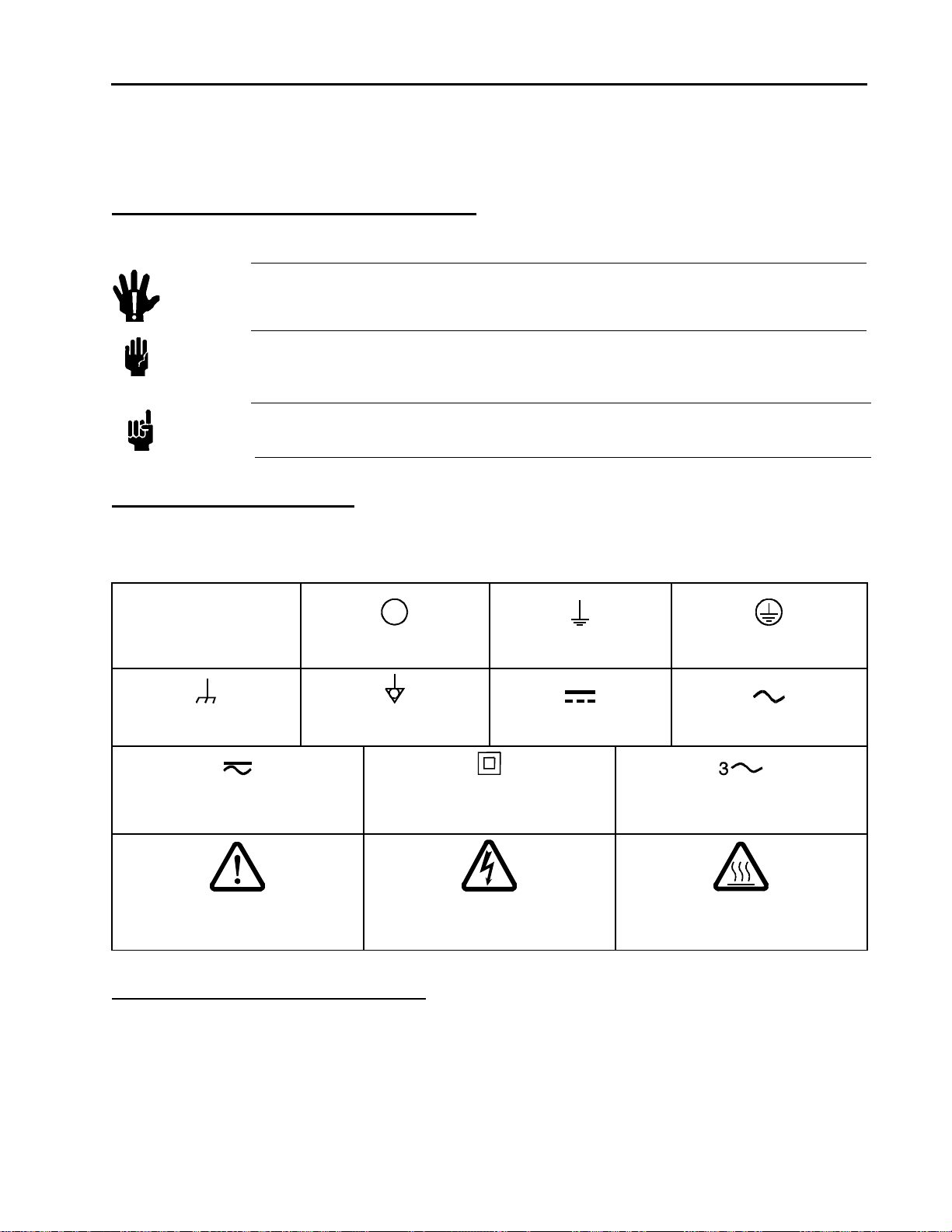
Symbols Found on the Unit
The following table describes symbols that may be found on the unit.
Table 1: Definition of Symbols Found on the Unit
|
On (Supply)
IEC 417, No. 5007
Frame or Chassis
IEC 417, No. 5020
Off (Supply)
IEC 417, No. 5008
Equipotentiality
IEC 417, No. 5021
Earth (ground)
IEC 417, No. 5017
Direct Current
IEC 417, No. 5031
Protective Earth (ground)
IEC 417, No. 5019
Alternating Current
IEC 417, No. 5032
Both Direct and Alternating Current
IEC 417, No. 5033-a
Caution (refer to accompanying
documents)
ISO 3864, No. B.3.1
Class II Equipment
IEC 417, No. 5172-a
Caution, Risk of Electric Shock
ISO 3864, No. B.3.6
Three Phase
Alternating Current
IEC 617-2, No. 020206
Caution, Hot Surface
IEC 417, No. 5041
Safety Procedures and Precautions
Observe the following general safety precautions during all phases of operation of this instrument.
Failure to comply with these precautions or with specific warnings elsewhere in thi s manual violates
safety standards of intended use of the instrument and may impair the protection provided by the
equipment. MKS Instruments, Inc. assumes no liability for the customer’s failure to comply with these
requirements.
1

Pressure Transducer Safety Information
DO NOT SUBSTITUTE PARTS OR MODIFY INSTRUMENT
Do not install substitute parts or perform any unauthorized modification to the instrument. Return the instrument to an
MKS Calibration and Service Center for service and repair to ensure that all safety features are maintained.
SERVICE BY QUALIFIED PERSONNEL ONLY
Operating personnel must not attempt component replacement and internal adjustments. Any service must be made by
qualified personnel only. Removing instrument covers voids the warranty for the device.
USE CAUTION WHEN OPERATING WITH HAZARDOUS MATERIALS
If hazardous materials are used, users must take responsibility to observe the proper safety precautions, completely purge
the instrument when necessary, and ensure that the material used is compatible with the wetted materials in this product,
including any sealing materials.
PURGE THE INSTRUMENT
After installing the unit, or before removing it from a system, purge the unit completely with a clean, dry gas to eliminate
all traces of the previously used flow material. Purge on install should involve pulling a vacuum on the system to
remove the previous gas (air), flooding with process gas.
USE PROPER PROCEDURES WHEN PURGING
This instrument must be purged under a ventilation hood, and gloves must be worn for protection. To purge this
instrument properly, it must be purged in both the horizontal base down and horizontal base up configurations as defined
in SEMI specification. Device has trapped volume in pressure sensor where gas which is lighter than air but still
hazardous can accumulate.
DO NOT OPERATE IN AN EXPLOSIVE ENVIRONMENT
To avoid explosion, do not operate this product in an explosive environment unless it has been specifically certified for
such operation.
USE PROPER FITTINGS AND TIGHTENING PROCEDURES
All instrument fittings must be consistent with instrument specifications, and compatible with the intended use of the
instrument. Assemble and tighten fittings according to manufacturer's directions.
CHECK FOR LEAK-TIGHT FITTINGS
Before proceeding to instrument setup, carefully check all plumbing connections to the instrument to ensure leak-tight
installation.
OPERATE AT SAFE INLET PRESSURES
Never operate at pressures higher than the rated maximum pressure (refer to the product specifications for the maximum
allowable pressure).
INSTALL A SUITABLE BURST DISC
When operating from a pressurized gas source, install a suitable burst disc in the vacuum system to prevent system
explosion should the system pressure rise.
KEEP THE UNIT FREE OF CONTAMINANTS
Do not allow contaminants to enter the unit before or during use. Contamination such as dust, dirt, lint, glass chips, and
metal chips may permanently damage the unit or contaminate the process.
ALLOW PROPER WARM UP TIME FOR TEMPERATURE-CONTROLLED UNITS
Temperature-controlled units will only meet specifications when sufficient time is allowed for the unit to meet, and
stabilize at, the designed operating temperature. Do not zero or calibrate the unit until the warm up is complete.
2
Sicherheitshinweise für den Druckmeßumformer
f
t
Sicherheitshinweise für den Druckmeßumformer
In dieser Betriebsanleitung vorkommende Symbole
Bedeutung der mit WARNUNG!, VORSICHT! und HINWEIS gekennzeichneten Absätze in dieser
Betriebsanleitung.
Warnung!
Vorsicht!
Das Symbol WARNUNG! weist auf eine Gefahr für das Bedienpersonal hin. Es
macht auf einen Arbeitsablauf, eine Arbeitsweise, einen Zustand oder eine
sonstige Gegebenheit aufmerksam, deren unsachgemäße Ausführung bzw.
ungenügende Berücksichtigung zu Verletzungen führen kann.
Das Symbol VORSICHT! weist auf eine Gefahr für das Gerät hin. Es macht au
einen Bedienungsablauf, eine Arbeitsweise oder eine sonstige Gegebenheit
aufmerksam, deren unsachgemäße Ausführung bzw. ungenügende
Berücksichtigung zu einer Beschädigung oder Zerstörung des Gerätes oder von
Teilen des Gerätes führen kann.
Hinweis
Das Symbol HINWEIS macht auf wichtige Informationen bezüglich eines
Arbeitsablaufs, einer Arbeitsweise, eines Zustands oder einer sonstige Gegebenhei
aufmerksam.
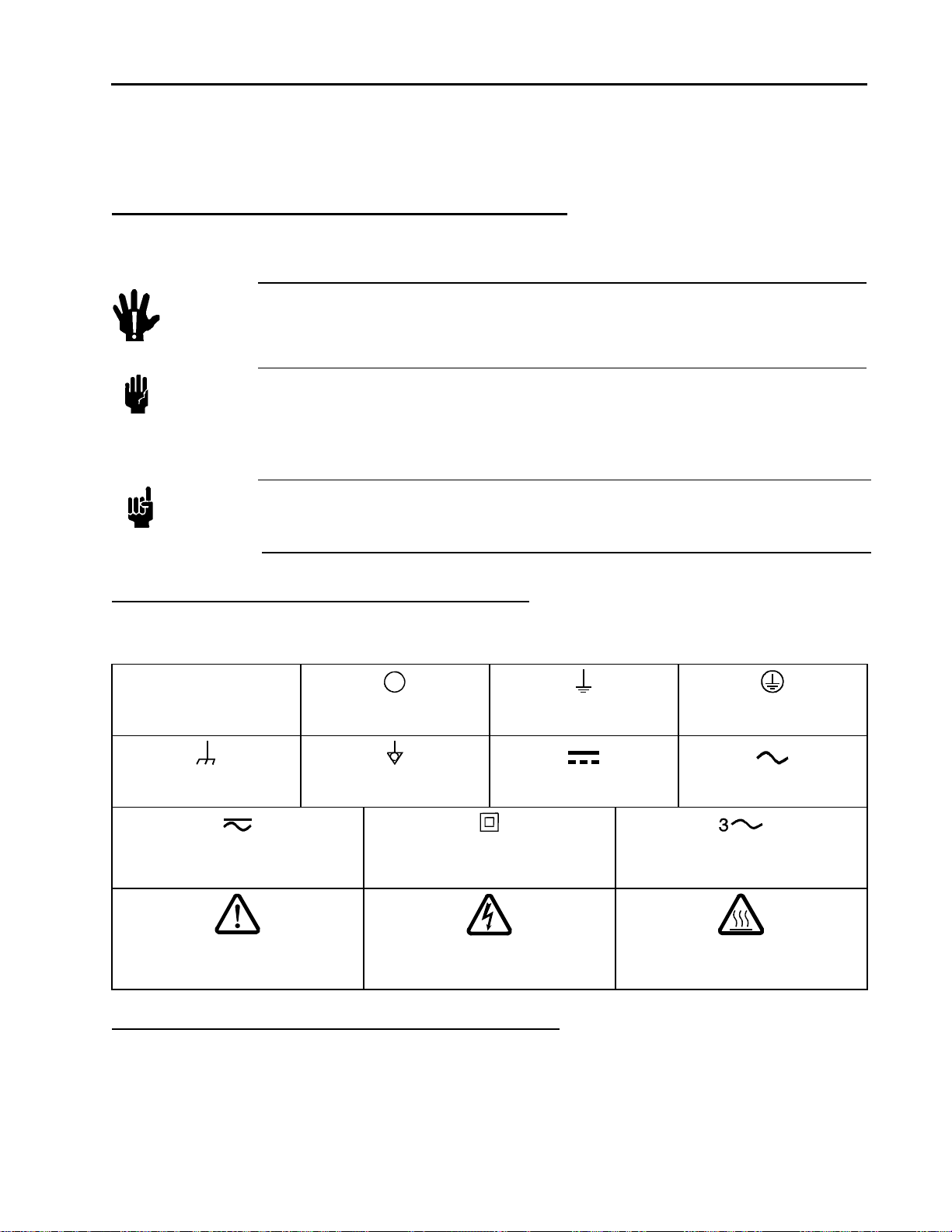
Erklärung der am Gerät angebrachten Symbole
Nachstehender Tabelle sind die Bedeutungen der Symbole zu entnehmen, die am Gerät angebracht sein können.
Tabelle 2: Bedeutung der am Gerät angebrachten Symbole
|
Ein (Energie)
IEC 417, No.5007
Aus (Energie)
IEC 417, No.5008
Erdanschluss
IEC 417, No.5017
Schutzleiteranschluss
IEC 417, No.5019
Masseanschluss
IEC 417, No.5020
Aquipotentialanschluss
IEC 417, No.5021
Gleichstrom
IEC 417, No.5031
Wechselstrom
IEC 417, No.5032
Gleich- oder Wechselstrom
IEC 417, No.5033-a
Durchgängige doppelte oder
verstärkte Isolierung
IEC 417, No.5172-a
Dreileiter-Wechselstrom (Drehstrom)
IEC 617-2, No.020206
Warnung vor einer Gefahrenstelle
(Achtung, Dokumentation beachten)
ISO 3864, No.B.3.1
Warnung vor gefährlicher
elektrischer Spannung
ISO 3864, No.B.3.6
Höhere Temperatur an leicht
zugänglichen Teilen
IEC 417, No.5041
Sicherheitsvorschriften und Vorsichtsmaßnahmen
Folgende allgemeine Sicherheitsvorschriften sind während allen Betriebsphasen dieses Gerätes zu
befolgen. Eine Missachtung der Sicherheitsvorschriften und sonstiger Warnhinweise in dieser
Betriebsanleitung verletzt die für dieses Gerät und seine Bedienung geltenden Sicherheitsstandards,
und kann die Schutzvorrichtungen an diesem Gerät wirkungslos machen. MKS Instruments, Inc.
haftet nicht für Missachtung dieser Sicherheitsvorschriften seitens des Kunden.
3

Sicherheitshinweise für den Druckmeßumformer
Niemals Teile austauschen oder Änderungen am Gerät vornehmen!
Ersetzen Sie keine Teile mit baugleichen oder ähnlichen Teilen, und nehmen Sie keine eigenmächtigen Änderungen am
Gerät vor. Schicken Sie das Gerät zwecks Wartung und Reparatur an den MKS-Kalibrierungs- und -Kundendienst ein.
Nur so wird sichergestellt, dass alle Schutzvorrichtungen voll funktionsfähig bleiben.
Wartung nur durch qualifizierte Fachleute!
Das Auswechseln von Komponenten und das Vornehmen von internen Einstellungen darf nur von qualifizierten
Fachleuten durchgeführt werden, niemals vom Bedienpersonal. Bei Entfernung von Geräteabdeckungen erlischt die
Garantie.
Vorsicht beim Arbeiten mit gefährlichen Stoffen!
Wenn gefährliche Stoffe verwendet werden, muß der Bediener die entsprechenden Sicherheitsvorschriften genauestens
einhalten, das Gerät, falls erforderlich, vollständig spülen, sowie sicherstellen, daß der Gefahrstoff die im Gerät
verwendeten medienberührenden Materialien, insbesondere Dichtungen, nicht angreift.
Spülen des Gerätes mit Gas!
Nach dem Installieren oder vor dem Ausbau aus einem System muß das Gerät unter Einsatz eines reinen Trockengases
vollständig gespült werden, um alle Rückstände des Vorgängermediums zu entfernen. Für die Spülung bei der
Installierung wird ein Vakuum an das System angelegt, um das (die) vorherige Gas (Luft) zu entfernen und das System
mit Prozessgas zu füllen.
Anweisungen zum Spülen des Gerätes
Das Gerät darf nur unter einer Ablufthaube gespült werden. Schutzhandschuhe sind zu tragen. Um eine korrekte
Spülung des Gerätes vorzunehmen, müssen Sie dieses in den beiden Konfigurationen horizontale Standfläche nach
unten und horizontale Standfläche nach oben entsprechend den SEMI-Spezifikationen spülen. Im Druckfühler des
Gerätes befindet sich ein Einschlussvolumen, in dem sich Gase, die leichter als Luft, aber dennoch gefährlich sind,
ansammeln können.
Gerät nicht zusammen mit explosiven Stoffen, Gasen oder Dämpfen benutzen!
Um der Gefahr einer Explosion vorzubeugen, darf dieses Gerät niemals zusammen mit (oder in der Nähe von)
explosiven Stoffen aller Art eingesetzt werden, sofern es nicht ausdrücklich für diesen Zweck zugelassen ist.
Anweisungen zum Installieren der Armaturen!
Alle Anschlußstücke und Armaturenteile müssen mit der Gerätespezifikation übereinstimmen, und mit dem geplanten
Einsatz des Gerätes kompatibel sein. Der Einbau, insbesondere das Anziehen und Abdichten, muß gemäß den
Anweisungen des Herstellers vorgenommen werden.
Verbindungen auf Undichtigkeiten prüfen!
Vor der Installierung des Gerätes, überprüfen Sie sorgfältig alle Geräteanschlüsse an Rohrleitungen auf undichte Stellen.
Gerät nur unter zulässigen Anschlußdrücken betreiben!
Betreiben Sie das Gerät niemals unter Drücken, die den maximal zulässigen Druck (siehe Produktspezifikationen)
übersteigen.
Geeignete Berstscheibe installieren!
Wenn mit einer unter Druck stehenden Gasquelle gearbeitet wird, sollte eine geeignete Berstscheibe in das
Vakuumsystem installiert werden, um eine Explosionsgefahr aufgrund von steigendem Systemdruck zu vermeiden.
Verunreinigungen im Gerät vermeiden!
Stellen Sie sicher, daß Verunreinigungen jeglicher Art weder vor dem Einsatz noch während des Betriebs in das
Instrumenteninnere gelangen können. Staub- und Schmutzpartikel, Glassplitter oder Metallspäne können das Gerät
dauerhaft beschädigen oder Prozeß und Meßwerte verfälschen.
Bei Geräten mit Temperaturkontrolle korrekte Anwärmzeit einhalten!
Temperaturkontrollierte Geräte arbeiten nur dann gemäß ihrer Spezifikation, wenn genügend Zeit zum Erreichen und
Stabilisieren der Betriebstemperatur eingeräumt wird. Kalibrierungen und Nulleinstellungen sollten daher nur nach
Abschluß des Anwärmvorgangs durchgeführt werden.
4
Informations relatives à la sécurité concernant le transducteur de pression
r
Informations relatives à la sécurité concernant le transducteur de
pression
Symboles utilisés dans ce manuel d'utilisation
Définitions des indications AVERTISSEMENT, MISE EN GARDE, et REMARQUE utilisées dans ce
manuel.
Avertissement
Attention
Un AVERTISSEMENT signale un danger pour le personnel. Elle attire
l'attention sur une procédure, une pratique, une condition, ou toute autre
situation présentant un risque de blessures pour le personnel, en cas
d'exécution incorrecte ou de non-respect des consignes.
Une MISE EN GARDE signale un danger pour l'appareil. Elle attire
l'attention sur une procédure d’emploi, une pratique, ou toute autre situation,
présentant un risque de dégât ou de destruction partielle ou totale du produit,
en cas d'exécution incorrecte ou de non-respect des consignes.
Remarque
Une REMARQUE signale une information importante. Elle attire l'attention su
une procédure, une pratique, une condition, ou toute autre situation, présentant un
intérêt particulier.
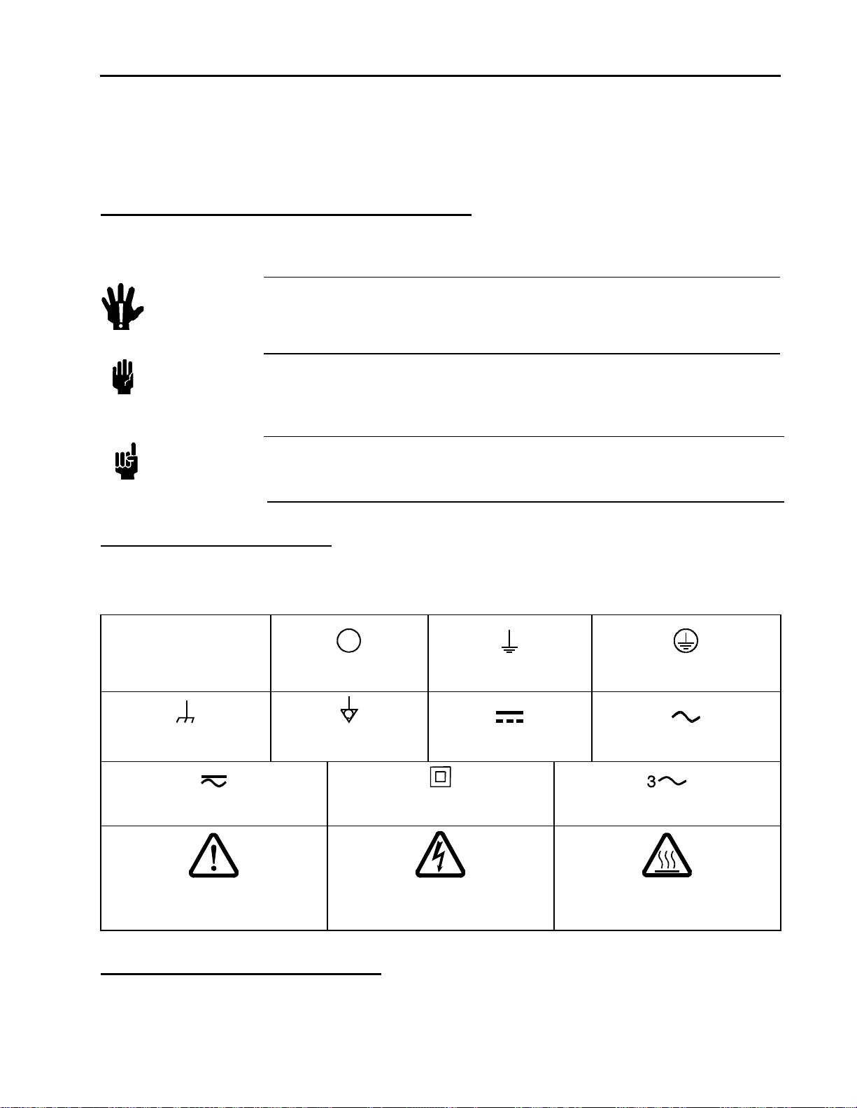
Symboles figurant sur l'unité
Le tableau suivant décrit les symboles pouvant apparaître sur l'unité.
Tableau 3: Définition des symboles sur l'unité
|
Marche (sous tension)
IEC 417, No.5007
Arrêt (hors tension)
IEC 417, No.5008
Terre (masse)
IEC 417, No.5017
Borne de protection (masse)
IEC 417, No.5019
Masse
IEC 417, No.5020
Courant continu et alternatif
IEC 417, No.5033-a
Mise en garde : se reporter
à la documentation
ISO 3864, No.B.3.1
Équipotentialité
IEC 417, No.5021
Courant continu
IEC 417, No.5031
Matériel de classe II
IEC 417, No.5172-a
Mise en garde : risque de
choc électrique
ISO 3864, No.B.3.6
Courant alternatif triphasé
Mise en garde : surface brûlante
Courant alternatif
IEC 417, No.5032
IEC 617-2, No.020206
IEC 417, No.5041
Mesures de sécurité et précautions
Observer les précautions générales de sécurité suivantes pendant toutes les phases du fonctionnement
de cet appareil. Le non-respect de ces précautions ou des avertissements du manuel constitue une
5

Informations relatives à la sécurité concernant le transducteur de pression
violation des normes de sécurité relatives à l'utilisation de l'appareil et peut compromettre la protection
assurée par l'appareil. MKS Instruments, Inc. dénie toute responsabilité en cas de non-respect des
consignes par les clients.
NE PAS SUBSTITUER DE PIÈCES NI MODIFIER L'APPAREIL
Ne pas susbstituer des pièces ni effectuer des modifications non autorisées sur l'appareil. Renvoyer l'appareil à un centre
de réparation et de calibrage MKS pour toute intervention ou réparation afin de garantir l'intégrité des dispositifs de
sécurité.
FAIRE RÉPARER UNIQUEMENT PAR DU PERSONNEL QUALIFIÉ
Le personnel d'exploitation ne doit pas tenter de remplacer des composants ou d’effectuer des réglages internes. Toute
intervention ne doit être effectuée que par du personnel qualifié. Le retrait des couvercles de l’appareil annule la garantie
du dispositif.
FAIRE PREUVE DE PRUDENCE EN CAS D'UTILISATION AVEC DES MATIÈRES DANGEREUSES
Si des matières dangereuses sont utilisées, l'utilisateur doit prendre des précaution appropriées, purger complètement
l'appareil lorsque cela est nécessaire et s’assurer que les produits utilisés sont compatibles avec les composants
humidifiés de cet appareil, y compris les matériaux d'étanchéité.
PURGER L'APPAREIL
Après l'installation de l'unité, ou avant son retrait d'un système, purger l'unité complètement avec un gaz propre et sec
afin d'éliminer toute trace du produit de débit usagé. La purge après l’installation devrait consister en une mise sous vide
du système afin d’éliminer le gaz précédent (air), pour que puisse s’écouler à la place le gaz utilisé.
UTILISER LES PROCÉDURES APPROPRIÉES POUR LA PURGE
Cet appareil doit être purgé sous une hotte de ventilation. Il faut porter des gants de protection. Pour purger correctement
l’appareil, ce dernier doit être purgé tant dans les configurations à base inférieure qu’à base supérieure, tel que le stipule
la spécification SEMI. Un certain volume peut être emprisonné dans le capteur de pression de l’appareil où du gaz, plus
léger que l’air mais quand même dangereux, peut s’accumuler.
NE PAS FAIRE FONCTIONNER DANS UN ENVIRONNEMENT EXPLOSIF
Pour éviter toute explosion, ne pas utiliser cet appareil dans un environnement explosif, sauf en cas d'homologation
spécifique pour un tel usage.
UTILISER LES BONS RACCORDS ET PROCÉDURES DE SERRAGE
Tous les raccords de l'appareil doivent être conformes à ses spécifications et compatibles avec l'usage prévu de l'appareil.
Assembler et serrer les raccords conformément aux directives du fabricant.
VÉRIFIER L'ÉTANCHÉITÉ DES RACCORDS
Avant de procéder au montage de l’appareil, vérifier avec soin tous les raccordements à l’appareil afin de garantir
l'étanchéité de l'installation.
UTILISER À DES PRESSIONS D'ADMISSION SÛRES
Ne jamais faire fonctionner l’appareil à des pressions supérieures à la pression nominale maximale (se reporter aux
spécifications de l'unité pour la pression maximale permise).
INSTALLER UN DISQUE D'ÉCHAPPEMENT ADAPTÉ
Lors du fonctionnement avec une source de gaz sous pression, installer un disque de rupture adapté dans le système à
vide, afin d'éviter l’explosion du système en cas d'augmentation de la pression.
GARDER L'UNITÉ LIBRE DE TOUT CONTAMINANT
Ne pas laisser des contaminants pénétrer dans l'unité avant ou pendant l'utilisation. Les contaminants tels que la
poussière, la saleté, les peluches, les petits éclats dde verre et de métal peuvent endommager l'unité d'une manière
permanente ou contaminer le processus.
RESPECT DU TEMPS D'ÉCHAUFFEMENT APPROPRIÉ POUR LES UNITÉS Á TEMPÉRATURE CONTRÔLÉE
Les unités à température contrôlée n’atteignent leurs spécifications que lorsqu’on leur laisse suffisamment de temps pour
atteindre d'une manière stable leur température de fonctionnement. Ne pas remettre à zéro ou calibrer l'unité tant que
l'échauffement n'est pas terminé.
6
Medidas de seguridad del transductor de presión
Medidas de seguridad del transductor de presión
Símbolos usados en este manual de instrucciones
Definiciones de los mensajes de advertencia, precaución y de las notas usados en el manual.
Advertencia
Precaución
El símbolo de advertencia indica la posibilidad de que se produzcan daños
personales. Pone de relieve un procedimiento, práctica, estado, etc. que en caso
de no realizarse o cumplirse correctam ente puede causar da ños personal es.
El símbolo de precaución indica la posibilidad de producir daños al equipo.
Pone de relieve un procedimiento operativo, práctica, etc. que en caso de no
realizarse o cumplirse correctamente puede causar daños o la destrucción total
o parcial del equipo.
Nota
El símbolo de notas indica información de importancia. Este símbolo pone de relieve
un procedimiento, práctica o condición cuyo conocimiento es esencial destacar.
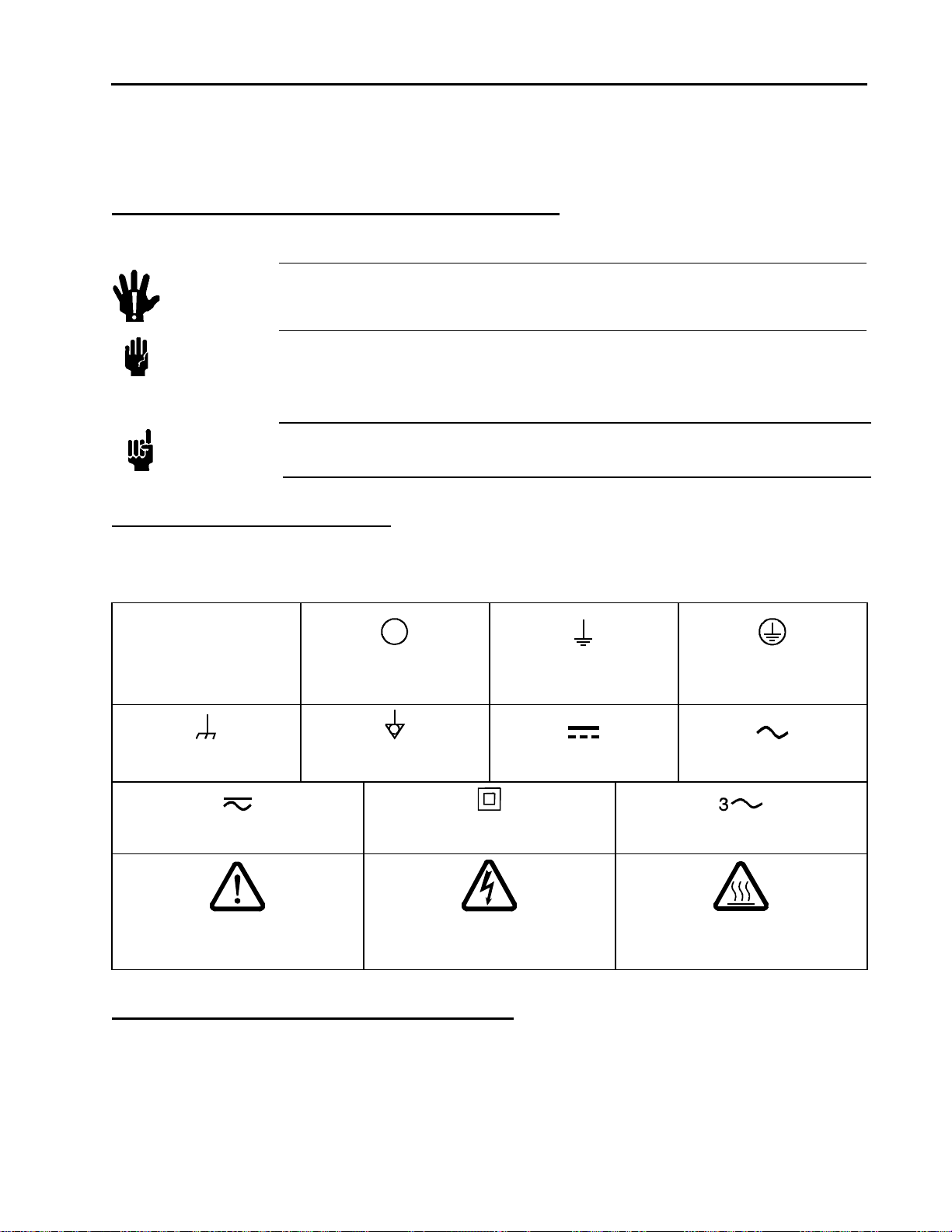
Símbolos hallados en la unidad
La tabla siguiente contiene los símbolos que puede hallar en la unidad.
Tabla 4: Definición de los símbolos hallados en la unidad
|
Encendido
(alimentación eléctrica)
IEC 417, N° 5007
(alimentación eléctrica)
IEC 417, N° 5008
Apagado
Puesta a tierra
IEC 417, N° 5017
Protección a tierra
IEC 417, N° 5019
Caja o chasis
IEC 417, N° 5020
Equipotencialidad
IEC 417, N° 5021
Corriente continua y alterna
IEC 417, N° 5033-a
Precaución. Consulte los documentos
adjuntos
ISO 3864, N° B.3.1
Corriente continua
IEC 417, N° 5031
Equipo de clase II
IEC 417, N° 5172-a
Precaución.
Riesgo de descarga eléctrica
ISO 3864, N° B.3.6
Corriente alterna trifásica
IEC 617-2, N° 020206
Precaución. Superficie caliente
Corriente alterna
IEC 417, N° 5032
IEC 417, N° 5041
Procedimientos y precauciones de seguridad
Las medidas generales de seguridad descritas a continuación deben observarse durante todas las etapas
de funcionamiento del instrumento. La fMFC de cumplimiento de dichas medidas de seguridad o de las
advertencias específicas a las que se hace referencia en otras partes de este manual, constituye una
violación de las normas de seguridad establecidas para el uso previsto del instrumento y podría anular
7

Medidas de seguridad del transductor de presión
la protección proporcionada por el equipo. Si el cliente no cumple dichas precauciones y advertencias,
MKS Instruments, Inc. no asume responsabilidad legal alguna.
NO UTILICE PIEZAS NO ORIGINALES O MODIFIQUE EL INSTRUMENTO
No instale piezas que no sean originales ni modifique el instrumento sin autorización. Para asegurar el correcto
funcionamiento de todos los dispositivos de seguridad, envíe el instrumento al Centro de servicio y calibración de MKS
toda vez que sea necesario repararlo o efectuar tareas de mantenimiento.
LAS REPARACIONES DEBEN SER EFECTUADAS ÚNICAMENTE POR TÉCNICOS AUTORIZADOS
Los operarios no deben intentar reemplazar los componentes o realizar tareas de ajuste en el interior del instrumento. Las
tareas de mantenimiento o reparación deben ser realizadas únicamente por personal autorizado. Si se retiran las tapas del
instrumento, quedará anulada la garantía del dispositivo.
TENGA CUIDADO CUANDO TRABAJE CON MATERIALES TÓXICOS
Cuando se utilicen materiales tóxicos, es responsabilidad de los operarios tomar las medidas de seguridad
correspondientes, purgar totalmente el instrumento cuando sea necesario y comprobar que el material utilizado sea
compatible con los materiales humedecidos del instrumento e inclusive, con todos los materiales de sellado.
PURGUE EL INSTRUMENTO
Una vez instalada la unidad o antes de retirarla del sistema, purgue completamente la unidad con gas limpio y seco para
eliminar todo resto de la sustancia líquida empleada anteriormente. El purgado de la instalación supondrá la creación del
vacío en el sistema para eliminar el gas (aire) previo, inundándolo con gas procesado.
USE PROCEDIMIENTOS ADECUADOS PARA REALIZAR LA PURGA
El instrumento debe purgarse debajo de una campana de ventilación y deben utilizarse guantes protectores. Para purgar
adecuadamente este instrumento, se debe purgar con las configuraciones de base horizontal hacia abajo y de base
horizontal hacia arriba, según se define en la especificación SEMI. El dispositivo tiene un volumen atrapado en el sensor
de presión, donde se puede acumular el gas que es más ligero que el aire, pero aún así peligroso.
NO HAGA FUNCIONAR EL INSTRUMENTO EN AMBIENTES CON RIESGO DE EXPLOSIÓN
Para evitar que se produzcan explosiones, no haga funcionar este instrumento en un ambiente con riesgo de explosiones,
excepto cuando el mismo haya sido certificado específicamente para tal uso.
USE ACCESORIOS ADECUADOS Y REALICE CORRECTAMENTE LOS PROCEDIMIENTOS DE AJUSTE
Todos los accesorios del instrumento deben cumplir las especificaciones del mismo y ser compatibles con el uso que se
debe dar al instrumento. Arme y ajuste los accesorios de acuerdo con las instrucciones del fabricante.
COMPRUEBE QUE LAS CONEXIONES SEAN A PRUEBA DE FUGAS
Antes de poner en marcha el sistema, inspeccione cuidadosamente las conexiones de tubos con el instrumento para
comprobar que hayan sido instaladas a prueba de fugas.
HAGA FUNCIONAR EL INSTRUMENTO CON PRESIONES DE ENTRADA SEGURAS
No haga funcionar nunca el instrumento con presiones superiores a la máxima presión nominal (en las especificaciones
del instrumento hallará la presión máxima permitida).
INSTALE UNA CÁPSULA DE SEGURIDAD ADECUADA
Cuando el instrumento funcione con una fuente de gas presurizado, instale una cápsula de seguridad adecuada en el
sistema de vacío para evitar que se produzcan explosiones cuando suba la presión del sistema.
MANTENGA LA UNIDAD LIBRE DE CONTAMINANTES
No permita el ingreso de contaminantes en la unidad antes o durante su uso. Los productos contaminantes tales como
polvo, suciedad, pelusa, lascas de vidrio o virutas de metal pueden dañar irreparablemente la unidad o contaminar el
proceso.
CALIENTE ADECUADAMENTE LAS UNIDADES CONTROLADAS POR MEDIO DE TEMPERATURA
Las unidades controladas por medio de temperatura funcionarán de acuerdo con las especificaciones sólo cuando se las
caliente durante el tiempo suficiente para permitir que lleguen y se estabilicen a la temperatura de operación indicada.
No calibre la unidad y no la ponga en cero hasta que finalice el procedimiento de calentamiento.
8

Chapter One: General Information Introduction
Chapter One: General Information
Introduction
MKS Instruments π series digital active pressure controllers (πPC) represent state-of-the-art technology
meeting the advanced process requirements of next generation toolsets. This unique device integrates MKS
Baratron® technology with a normally-closed or normally-open proportioning control valve, (optional)
integrated flow meter, and closed-loop control electronics through an innovative, real-time feedback control
system.
The πPCs include an integrated multifunctional local display, Ethernet connectivity, and an embedded, webbased user interface that offers E-diagnostics. The device is available in either standard 1.125” C-seal and Wseal surface mount or ¼” VCR™ process connections.
Design Features
Increases Throughput and Performance
♦ Integral Baratron® capacitance manometer technology provides accuracy, reliability and rangeability
from 2% to 100% full scale.
♦ Available with Full Scale pressure ranges as low as 100 Torr for use in low-pressure processes.
♦ Available as an upstream system backpressure or downstream controller.
♦ Increases tool uptime through reduction of “No Problem Found” πPC replacements.
♦ Includes embedded diagnostics software that allows users to check πPC functionality without
removing the device.
♦ E-diagnostics through embedded Ethernet interface.
♦ Programmable high and low limit alarm and warnings for process limit control.
Reduce Overall Costs
♦ Reduces overall system cost while saving valuable rack space through minimized footprint.
♦ Reduce inventory through multi-gas, multi-range availability for units with optional integrated flow
meter.
Easy to Integrate and Operate
♦ Straightforward configuration and diagnostics through Ethernet interface
Uses HTML 2.0 compatible web browser – no special software required.
Includes remote πPC application.
♦ Easy viewing of device configuration, full-scale pressure, (optional) full-scale flow rate and gas type,
and Ethernet IP address with big LED display.
9

Introduction Chapter One: General Information
Model Name( Part Number ) PC90 (PCA0) PC99 (P99A)
Absolute Pressure Yes Yes
Control Direction Upstream and Downstream Downstream Only
Integrated Flow Meter No Yes
MG(Multi Gas) Flow N/A Yes
MR(Multi Range) Flow N/A Yes
The design of the
πPC PC99 incorporates an advanced flow sensor and an optimized bypass. The latest
generation two-element sensing circuit provides accurate, repeatable flow measurement performance even in
low flow ranges (as low as 10sccm full-scale range). A low temperature effect from ambient temperature
change and a low attitude sensitivity effect are also ensured. Attitude sensitivity is completely accounted for
with advanced attitude circuitry. The optimized sensor/bypass arrangement minimizes the flow splitting error
when gases other than the calibration gas are used; dramatically improving measurement accuracy.
Digital Features
The DeviceNet interface ensures interoperability in any DeviceNet pressure control application. In addition,
the true digital calibration and valve control electronics, coupled with default 11 point pressure calibration,
provide for high pressure accuracy over a wide range of setpoints and fast response to even low setpoints.
Reliability
To provide excellent reliability, the design contains a low mechanical and electronic components count and
has successfully passed the following test:
STRIFE, including temperature cycling and vibration (sine and random tests)
And with a metal braided, shielded cable, properly grounded at both ends:
EMC Directive 89/336/EEC for CE Mark compliance
Cleanliness Features
πPCs use only metal for all external seals. The metal seals eliminate gas permeation and ensure
The
extremely low external leakage under pressure or vacuum conditions relative to atmosphere. The internal
valve control plug is Teflon or sapphire, which are pure, chemically stable, and not prone to out-gassing or
particle generation. The
πPCs mechanical design incorporates minimal wetted surface area assuring rapid dry-
down. Its construction minimizes trapped volume enhancing product safety and eliminating troublesome
virtual leaks. To further enhance its cleanliness, all internal surfaces are precision machined and
electropolished to a 5Ra surface finish. The instrument is assembled and double-packaged in a Class 100
clean room environment.
10

Chapter One: General Information How This Manual is Organized
How This Manual is Organized
Before installing the device in a system and/or operating it, carefully read and familiarize yourself with
all precautionary notes in the Pressure Transducer Device Safety Information section at the front of this
manual. In addition, observe and obey all
manual.
Chapter One: General Information, (this chapter) introduces the product and describes the organization of
this manual.
Chapter Two: Installation and Configuration explains the environmental requirements and describes how to
mount the instrument in your system.
Chapter Three: Ethernet Interface Setup and Configuration explains how to prepare your computer network
to talk to a πPC using the Ethernet interface. It also explains how to use the web-base browser interface to
setup, configure and run diagnostics on your πPC.
Chapter Four: Embedded Web-Based GUI and Diagnostics takes a detailed look at the Embedded WebBased Graphical User Interface (GUI) and its features, specifically E-Diagnostics.
Chapter Five: Overview provides a brief description of the instrument and its functionality, describes how to
use the instrument, explains all the functions and features and also provides instruction on tuning the device.
WARNING and CAUTION notes provided throughout the
Chapter Six: Maintenance lists any maintenance required to keep the instrument in good working condition.
Chapter Seven: Troubleshooting provides a reference should the instrument appear to malfunction.
Appendix A: Product Specifications for the PC90 Model lists the specifications of the instrument.
Appendix B: Model Code Explanation for the PC90 Model describes the PC90 model code.
Appendix C: Product Specifications for the PC99 Model lists the specifications of the instrument.
Appendix D: Model Code Explanation for the PC99 Model describes the PC99 model code.
Appendix E: Valve Orifice Selection describes how to select the correct orifice for the πPC.
11

Customer Support Chapter One: General Information
Customer Support
Standard maintenance and repair services are available through all of the regional MKS Calibration and
Service Centers.
If any difficulties arise in the use of your device, or to obtain information about companion products MKS
offers, contact any authorized MKS Calibration and Service Center. If it is necessary to return the instrument
to MKS, then two actions must be completed before shipping: (1) a RMA (Return Material Authorization)
number must be obtained and (2) a Health and Safety Form must be completed and included with the
instrument.
Warning
All returns to MKS Instruments must be purged so it is free of harmful, corrosive,
radioactive, or toxic materials.
To purge this instrument properly, it must be purged in both the horizontal base
down and horizontal base up configurations as defined in SEMI specification. The
device has trapped volume in the pressure sensor where gas lighter than air but
still HAZARDOUS can accumulate.
Obtaining a RMA number
RMA (Return Material Authorization) numbers expedite handling and ensure proper servicing of your
instrument.
RMA numbers can be obtained by contacting the MKS Calibration and Service Center or through the MKS
website at:
http://www.mksinst.com/service/servicehowtoorder.aspx.
Note
Returned instruments will not be accepted without a valid RMA number displayed on the
shipping container.
Health and Safety form
A returned instrument will not be examined without a signed Health and Safety form indicating that the unit is
free of harmful materials.
The Health and Safety form can be obtained on the last page of this manual or through the MKS website at:
http://www.mksinst.com/service/servicehowtoorder.aspx.
Note
Returned instruments will not be examined without a signed certificate indicating the
instruments are free of harmful materials.
Please refer to the inside of the back cover of this manual for a list of MKS Calibration and Service Centers.
12

Chapter Two: Installation and Configuration
Unpacking the πPC
Chapter Two: Installation and Configuration
Unpacking the πPC
MKS has carefully packaged your device so that it will reach you in perfect operating order. Upon receiving
the unit, however, you should check for defects, cracks, broken connectors, etc., to be certain that damage has
not occurred during shipment.
Note
Do not discard any packing materials until you have completed your inspection and are sure the
unit arrived safely.
If you find any damage, notify your carrier and MKS immediately. If it is necessary to return the unit to
MKS, please refer to the Customer Support section of Chapter 1 on page 12 for instructions on obtaining a
RMA (Return Material Authorization) number and details on the Health and Safety form that is required with
every return.
Opening the Package
Each device is assembled, leak tested with helium, and calibrated in a cleanroom environment. The
instrument is double-packaged in this environment to ensure maintenance of its particle free condition during
shipment. It is very important to remove the packaging according to good clean room practices. To maintain
at least a minimal level of clean room standards, follow the instructions below:
1. Remove all cardboard and packaging materials. Discard before entering the garmenting room.
2. Remove the outer plastic shipping container in an ante room (garmenting room) or transfer box. Do not
allow this container to enter the clean room.
3. Remove the inner bag in the clean room.
4. Inspect for any damage.
5. Pass the original calibration sheet(s) to the appropriate personnel at your company.
6. For surface mount πPCs, remove the Ethernet kit and adapter cable (RS-485 and Analog only) from the
inner container and DO NOT take into clean room.
Caution
Only qualified individuals should perform the installation and any user configuration.
Individuals must comply with all necessary ESD handling precautions while installing
the instrument. Proper handling is essential when working with all highly sensitive
precision electronic instruments.
Unpacking Checklist
Standard Equipment:
πPC
πPC Instruction Manual (this book)
Ethernet Kit (Surface Mount πPCs only)
Adapter cables for 9 pin RS-485 and 15 pin analog devices (Surface Mount πPCs only)
13

Product Location and Requirements Chapter Two: Installation and Configuration
Pressure calibration sheet (Type PC90 & PC99)
Flow calibration sheet (Type PC99 only)
Optional Equipment:
RS-485 Connector Accessory
Interface cables
Product Location and Requirements
Ventilation requirements include sufficient air circulation with 0.25” on each side of the device to allow
convection cooling of internally generated valve heat.
Ambient operating temperature range: 10° to 50° C (50° to 122° F)
Power requirement:
1. Analog & RS-485: +15.0 to +24.0 VDC @ 350mA max
2. DeviceNet: +11.0 to +25.0 VDC [320 mA maximum current @ 11 VDC
146 mA @ 24 VDC nominal]
Storage temperature range: -20° to 80° C (-4° and 176° F)
Mount the πPC in an upright position if possible for easy viewing of the display during configuration,
although any mounting orientation is satisfactory during normal operation. The local display can be
rotated 270° so that it can be easily read in any orientation.
Install a separate positive shutoff valve if your system cannot tolerate any leakage through the πPC. The
internal proportional control valve is not a positive shutoff valve so some leakage across the valve may
occur.
Warning
Install the πPC in a “flowing” system where gas is continually added and evacuated. Do not use the
Your corporate policy on handling toxic or hazardous gases supersedes the
instructions in this manual. Comply with your corporate policy. MKS assumes no
liability for the safe handling of such materials.
controller in a “dead-ended” system (a system which cannot remove excess mass). The πPC can not vent
excess mass to the atmosphere.
Verify that your pressure system can withstand pressure equal to the full scale range of the transducer.
Your pressure system may be exposed to the full scale pressure since the πPC controller will control over
the entire full scale range of the transducer. As a precaution, you may choose to install a safety valve in
your system to vent excess pressure.
Take care not to expose the transducer to pressures above its full scale range. Pressures exceeding twice
the full scale pressure may cause zero-drift or damage the transducer. Pressures exceeding the full scale
range can cause loss of calibration and NIST traceability.
For a PC99 Only, the control valve inside the PC99 is rated for a maximum gas inlet pressure of 150 psig.
Ensure that the inlet pressure is consistent with the differential pressure limit of the pressure transducer.
Caution
Exposing the pressure transducer to pressures exceeding twice the full scale pressure
for extended periods of time may cause zero drift or damage the pressure transducer.
Sub-atmospheric sensors must not be exposed to pressures greater than one
atmosphere.
14

Chapter Two: Installation and Configuration Dimensions
t
Warm up time and zeroing:
1. πPC and Pressure sensor warm up
: After installation and power up, allow the πPC to warm
up for a minimum of 30 minutes while under vacuum. This will require opening the device’s
process control valve. Refer to the Opening & Closing the
π
PC’s Process Control Valve
section of Chapter 6 on page 82 for instructions on opening the valve.
2. Zeroing: After the warm up is complete, the πPC needs to be zeroed. Refer to the Zero
Adjustment section of Chapter 6 on page 79 for more on the zeroing procedure.
Use high purity gas filters in line upstream of the device to prevent contamination of precision flow
orifices and proper bypass operation (for PC99).
For additional information on the PC90 refer to Appendix A, Product Specifications for the PC90 Model,
on page 91.
For additional information on the PC99 refer to Appendix C, Product Specifications for the PC99 Model,
on page 99.
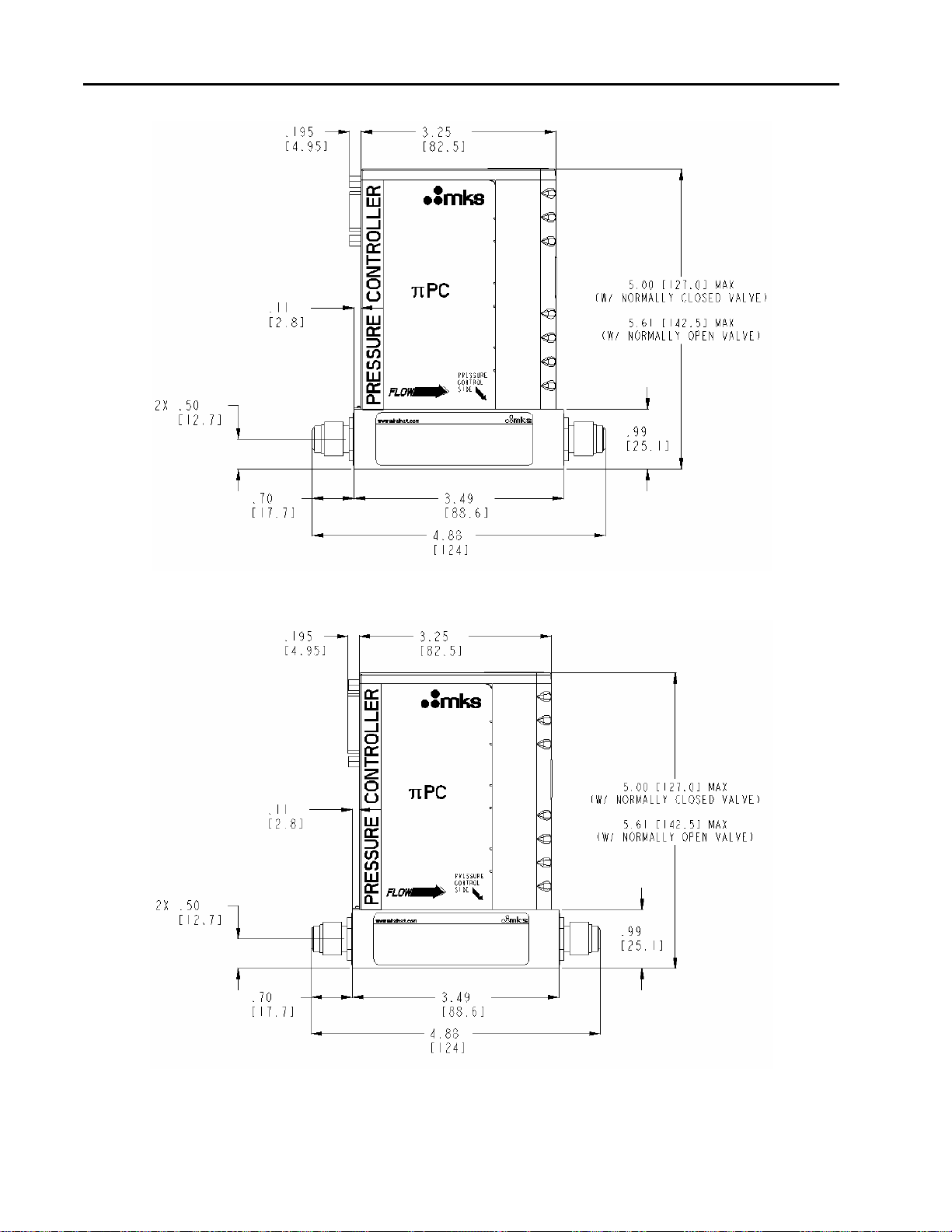
Dimensions
Refer to the applicable drawings, which follow.
Note
Height dimensions are given for a πPC with a Normally Closed (N.C.) valve and a πPC with a
Normally Open (N.O.) valve. To determine if the πPC has a Normally Open valve view the
back side of the device. Directly above the pinout information you will see the tex
“NORMALLY OPEN VALVE”.
Figure 1: 4-VCR Front View – DeviceNet
15
Dimensions Chapter Two: Installation and Configuration
Figure 2: 4-VCR Front View – 9-Pin D RS-485
Figure 3: 4-VCR Front View – 15-Pin D Analog
16
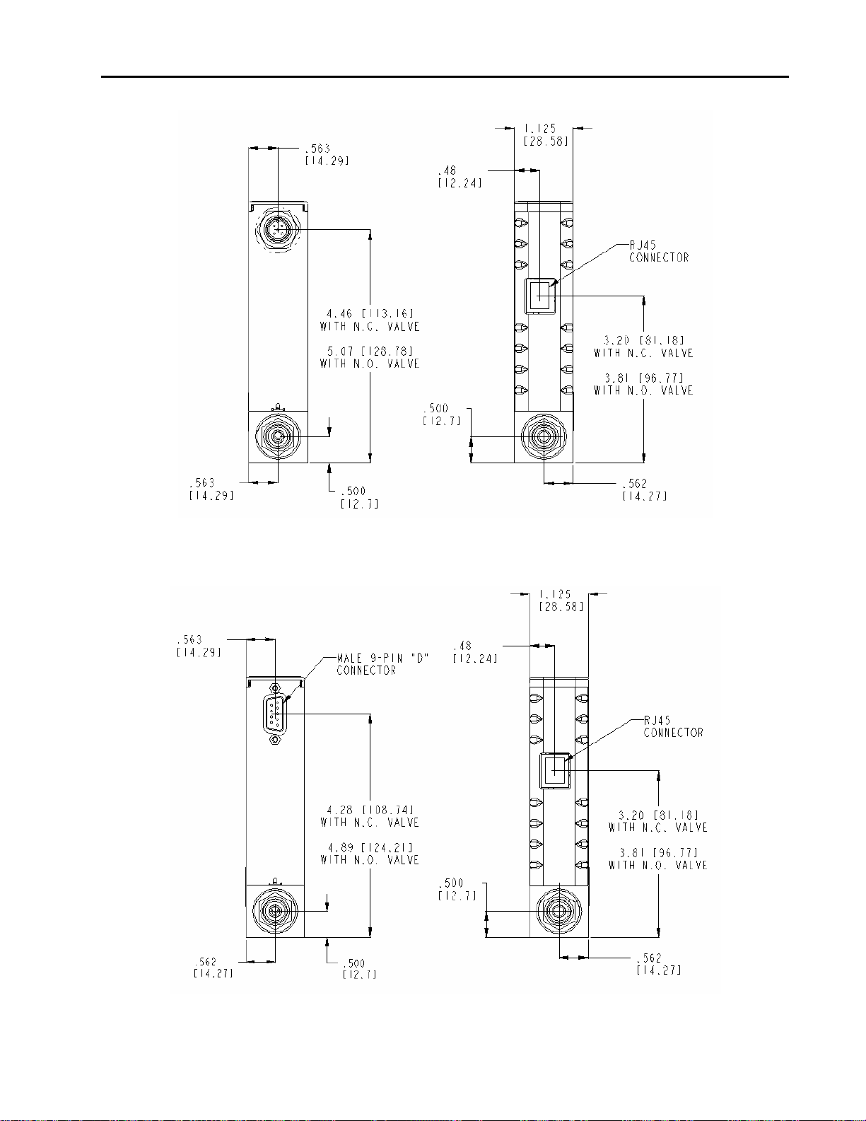
Chapter Two: Installation and Configuration Dimensions
Figure 4: 4-VCR Left and Right Side Views – DeviceNet
Figure 5: 4-VCR Left and Right Side Views – 9-Pin D RS-485
17

Dimensions Chapter Two: Installation and Configuration
Figure 6: 4-VCR Left and Right Side Views – 15-Pin D Analog
Figure 7: 4-VCR Top View (15-Pin D Analog Shown)
Figure 8: 4-VCR Bottom View
18
 Loading...