

MKS Micro-Baratron 870B, Micro-Baratron 872B Instruction Manual

MKS Type 870B/872B
123655-P1
Rev A, 4/99
Instruction Manual
Micro-Baratron
®
Absolute Pressure Transducer
Six S hatt uck Road
Andover, MA 01810-2449
(800) 227-8766 or (978) 975-2350
Fax: (978) 975-0093
E-mai l: mks@mk sinst.com
Web site: http://www.mksinst.com

WARRANTY
Type 870B/872B Equipment
MKS Instruments, Inc. (
above (the “equipment”) manufactured by
correc tly perf orm al l d ate-relat ed operati ons , i nc lu ding wit ho ut li m it a ti on a cc e pting data entry, sequenci ng, s or t in g,
compa rin g, and rep ortin g, re gar dles s of t he dat e th e ope rat ion is perfo rm ed or th e dat e inv olv ed in t he ope rat ion,
provi ded that, if the equi pment exc hange s data or i s otherw ise us ed with equipm ent, sof twar e, or othe r produ cts
of othe rs, suc h pro duct s of othe rs th ems elves corr ectl y perfo rm al l date- rela ted op era tions and sto re a nd tr ans mit
dates and date-re lated data in a format comp atible with
WARRANTY CONCERNING DATE-RELATED OPERATIONS.
For the pe riod co mmenc ing with the date of shipmen t of this equi pment and endi ng two yea rs later ,
its op tion, eit her rep air or r eplac e any pa rt whic h is d efectiv e in m aterials or workm anship or wit h respe ct to t he
date-r e la te d operat io ns war ranty wi th out charge t o t h e p ur c ha s er. The fore go in g s ha ll constit ute the exc lu s iv e and
sole remedy of the purchaser for any breach by
The pu rc haser, before ret ur n in g an y equipm e nt c overed by this war ran t y , w h ic h is as s e r te d to be de fec tive by th e
purch ase r, sh al l make spec if ic wri tt en ar rang eme nts wit h re spect to the r espo nsi bility fo r s hipp ing the equ ip ment
and handling any other incidental charges with the
equipment was purchased or, in the case of a direct purchase from
Massac huse tts , USA.
This warranty does not apply to any equipment which has not been installed and used in accordance with the
specifications recommended by
under any circumstances for indirect, special, consequential, or incidental damages in connection with, or arising
out of, the sale, performance, or use of the equipment covered by this warranty.
MKS
recommends that all
mont hs) to ensu re accurat e readings. When a product is re turned t o
considered norma l preventative maintenance not covered by any warranty.
MKS
) warrant s that for two years from the date of shipment the equipm ent describe d
MKS
shal l be fre e from def ec ts i n mat eri als and work man shi p an d w ill
MKS
equipment. THIS WARRANTY IS
MKS
of this warranty.
MKS
sales representative or distributor from which the
MKS
, with the
MKS
for th e proper and nor mal use of the eq uipment.
MKS
pressure and fl ow products be calibrated periodi cally (typically every 6 to 12
MKS
MKS
home offic e in Andov er,
MKS
for this periodic re-calibrati on it is
MKS’
shall not be liable
MKS
SOLE
will, at
THIS WARRANTY IS IN LIEU OF ALL OTHER RELEVANT WARRANTIES, EXPRESSED OR IMPLIED,
INCLUDING THE IMPLIED WARRANTY OF MERCHANTABILITY AND THE IMPLIED WARRANTY OF FITNESS
FOR A PARTICULAR PURPOSE, AND ANY WARRANTY AGAINST INFRINGEMENT OF ANY PATENT.
11-98 123655-P1
SPECIAL NOTICE
This warranty is void if the product is installed using single or double metal ferrule compression
type vacuum fittings, shown below. These fittings are commonly tightened incorrectly, causing
damage to the pressure sensor.
Single Ferru le
Doub le Ferrule

MKS Type 870B/872B
123655-P1
Rev B, 06/01
Micro-Baratron
®
Absolute Pressure Transducer

Copyright © 2001 by MKS Instruments, Inc.
All rights reserved. No part of this work may be reproduced or transmitted in any form or
by any means, electronic or mechanical, including photocopying and recording, or by any
information storage or retrieval system, except as may be expressly permitted in writing by
MKS Instruments, Inc.
Printed in the United States of America
Baratron is a registered trademark of MKS Instruments, Inc., Andover, MA
Bendix is a registered trademark of Amphenol Corp., Bendix Connector Operations., Sidney,
NY
Inconel and Incoloy are registered trademarks of Inco Alloys International, Huntington, WV
Swagelok and VCR are registered trademarks of Swagelok Marketing Co., Solon, OH

Table of Contents
Table of Contents
Pressure Transducer Safety Information.............................................................................. 2
Symbols Used in This Instruction Manual................................................................. 2
Symbols Found on the Unit...................................................................................... 3
Safety Procedures and Precautions ..........................................................................4
Sicherheitshinweise für den Druckmeßumformer ..................................................................6
In dieser Betriebsanleitung vorkommende Symbole ................................................... 6
Erklärung der am Gerät angebrachten Symbole ........................................................ 7
Sicherheitsvorschriften und Vorsichtsmaßnahmen..................................................... 8
Informations relatives à la sécurité pour le transducteur de pression....................................... 10
Symboles utilisés dans ce manuel d'utilisation ............................................................10
Symboles apparaissant sur l'unité ............................................................................. 11
Mesures de sécurité et précautions .......................................................................... 12
Medidas de seguridad del transductor de presión................................................................... 14
Símbolos usados en este manual de instrucciones ......................................................14
Símbolos hallados en la unidad .................................................................................15
Procedimientos y precauciones de seguridad............................................................ 16
Chapter One: General Information...................................................................................... 19
Introduction............................................................................................................ 19
How This Manual is Organized................................................................................ 20
Customer Support ...................................................................................................20
Chapter Two: Installation ................................................................................................... 21
How To Unpack the Type 870/872 Unit................................................................... 21
Ultraclean Units ......................................................................................... 21
Unpacking Checklist................................................................................... 22
Product Location and Requirements......................................................................... 22
Operating Temperature ...............................................................................22
Power Requirements .................................................................................. 22
iii

Table of Contents
Interface Cables .....................................................................................................23
Setup..................................................................................................................... 25
Electrical Information.............................................................................................. 30
Connectors............................................................................................................. 33
Generic Shielded Cables.............................................................................. 24
Dimensions ................................................................................................ 25
Mounting Instructions ..................................................................................29
Welded Connections ................................................................................... 29
Mechanical Connections ............................................................................. 29
Voltage Unit ...............................................................................................30
Current Unit............................................................................................... 31
Flying Leads ...............................................................................................34
Bendix Connectors ..................................................................................... 35
Type “D” Connectors................................................................................. 36
Startup................................................................................................................... 38
Chapter Three: Overview................................................................................................... 39
General Information ................................................................................................39
Sensor ................................................................................................................... 39
Signal Conditioner ...................................................................................................39
Labels.................................................................................................................... 40
Serial Number Label................................................................................... 40
Information Label....................................................................................... 40
Bendix Connector Warning Label................................................................ 41
Chapter Four: Operation..................................................................................................... 43
How To Adjust the Zero .........................................................................................43
Chapter Five: Maintenance and Troubleshooting.................................................................. 45
General Information ................................................................................................45
Maintenance .......................................................................................................... 45
Zero Adjustment......................................................................................... 45
Troubleshooting...................................................................................................... 46
Appendix A: Product Specifications .................................................................................... 49
iv

Table of Contents
Performance Specifications..................................................................................... 49
Electrical Specifications .......................................................................................... 49
Physical Specifications............................................................................................ 50
Environmental Specifications ................................................................................... 51
Appendix B: Model Code Explanation................................................................................. 53
Model Code ........................................................................................................... 53
Index................................................................................................................................. 57
v


List of Figures
List of Figures
Figure 1: Dimensions of the Type 870 Transducer................................................................ 25
Figure 2: Dimensions of Additional Fittings for the Type 870 Transducer............................... 26
Figure 3: Dimensions of the Type 872 Transducer................................................................ 27
Figure 4: Dimensions of Additional Fittings for the Type 872 Transducer............................... 28
Figure 5: Electrical Scheme for a Voltage Unit .................................................................... 30
Figure 6: Line Resistance Equation ..................................................................................... 31
Figure 7: Total Resistance in Line ....................................................................................... 31
Figure 8: Electrical Scheme for a Current (4 to 20 mA) Unit .................................................32
Figure 9: Flying Leads........................................................................................................ 34
Figure 10: Bendix Connector .............................................................................................. 35
Figure 11: 9-Pin Standard Type “D” Connector ................................................................... 36
Figure 12: 15-Pin High Density Type “D” Connector ........................................................... 37
Figure 13: Serial Number Label ..........................................................................................40
Figure 14: Information Label............................................................................................... 40
Figure 15: Bendix Connector Warning Label........................................................................ 41
vii


Pressure Transducer Safety Information Symbols Used in This Instruction Manual
List of Tables
Table 1: Definition of Symbols Found on the Unit.....................................................................3
Tabelle 2: Bedeutung der am Gerät angebrachten Symbole.......................................................7
Tableau 3: Définition des symboles apparaissant sur l'unité ..................................................... 11
Tabla 4: Definición de los símbolos hallados en la unidad......................................................... 15
Table 5: Power Requirements............................................................................................... 22
Table 6: Interface Cables..................................................................................................... 24
Table 7: Connector Options .................................................................................................. 33
Table 8: Flying Lead Pinout (Model Code F).......................................................................... 34
Table 9: Flying Lead Pinout (Model Code L) ......................................................................... 34
Table 10: Bendix Connector Pinout (Model Code D) .............................................................. 35
Table 11: Bendix Connector Pinout (Model Code H) .............................................................. 36
Table 12: 9-Pin Standard Type “D” Connector Pinout............................................................ 36
Table 13: 15-Pin High Density Type “D” Connector Pinout.................................................... 37
Table 14: Highest Pressures Suggested for Proper Zero Adjustment....................................... 44
Table 15: Troubleshooting Chart ........................................................................................... 47
1
Symbols Used in This Instruction Manual Pressure Transducer Safety Information
Pressure Transducer Safety Information
Symbols Used in This Instruction Manual
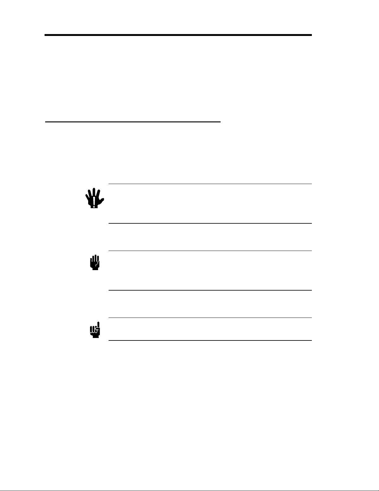
Definitions of WARNING, CAUTION, and NOTE messages used throughout the manual.
Warning
The WARNING sign denotes a hazard to personnel. It calls
attention to a procedure, practice, condition, or the like,
which, if not correctly performed or adhered to, could result
in injury to personnel.
Caution The CAUTION sign denotes a hazard to equipment. It calls
attention to an operating procedure, practice, or the like, which, if
not correctly performed or adhered to, could result in damage to or
destruction of all or part of the product.
Note
The NOTE sign denotes important information. It calls attention to a
procedure, practice, condition, or the like, which is essential to highlight.
2
Pressure Transducer Safety Information Symbols Found on the Unit
IEC 417, No.5019
Alternating current
IEC 417, No.5032
Both direct and
alternating current
IEC 417, No.5033-a
Three phase
alternating current
IEC 617-2 No.020206
Caution, refer to
accompanying
documents
ISO 3864, No.B.3.1
Caution, risk of
electric shock
ISO 3864, No.B.3.6
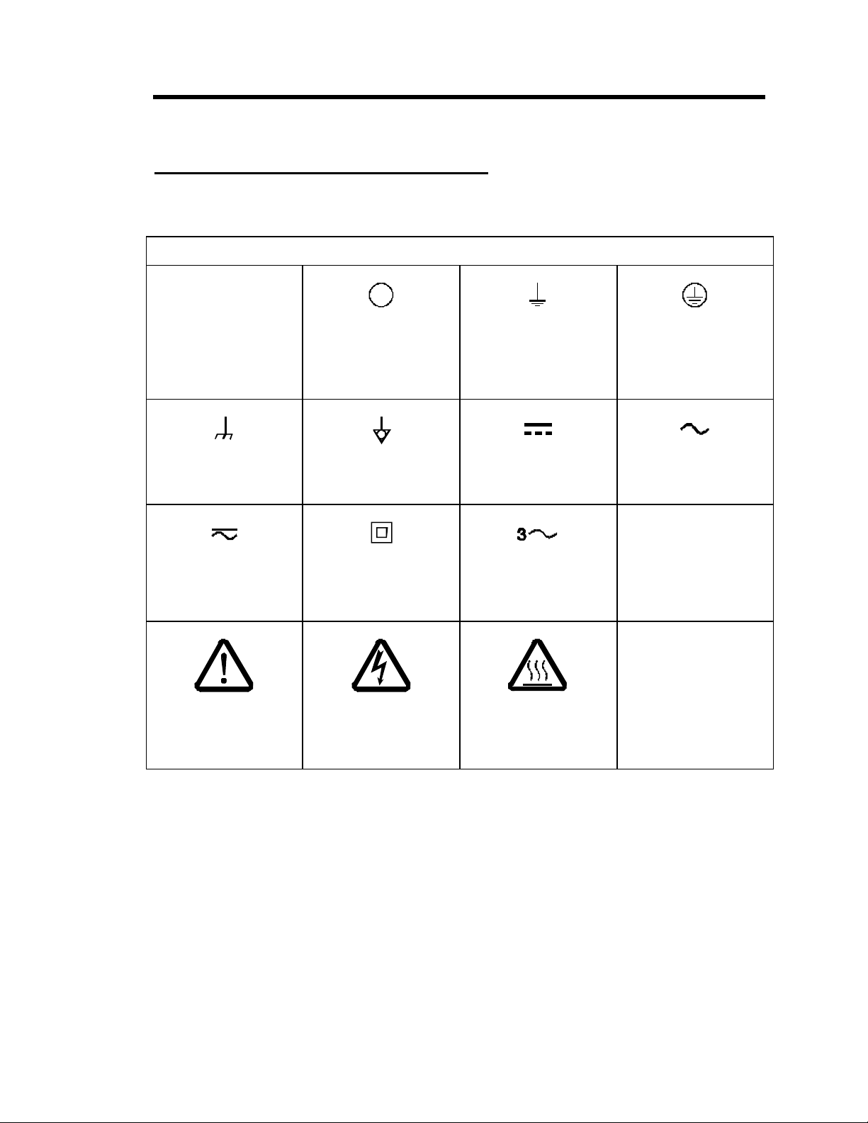
Symbols Found on the Unit
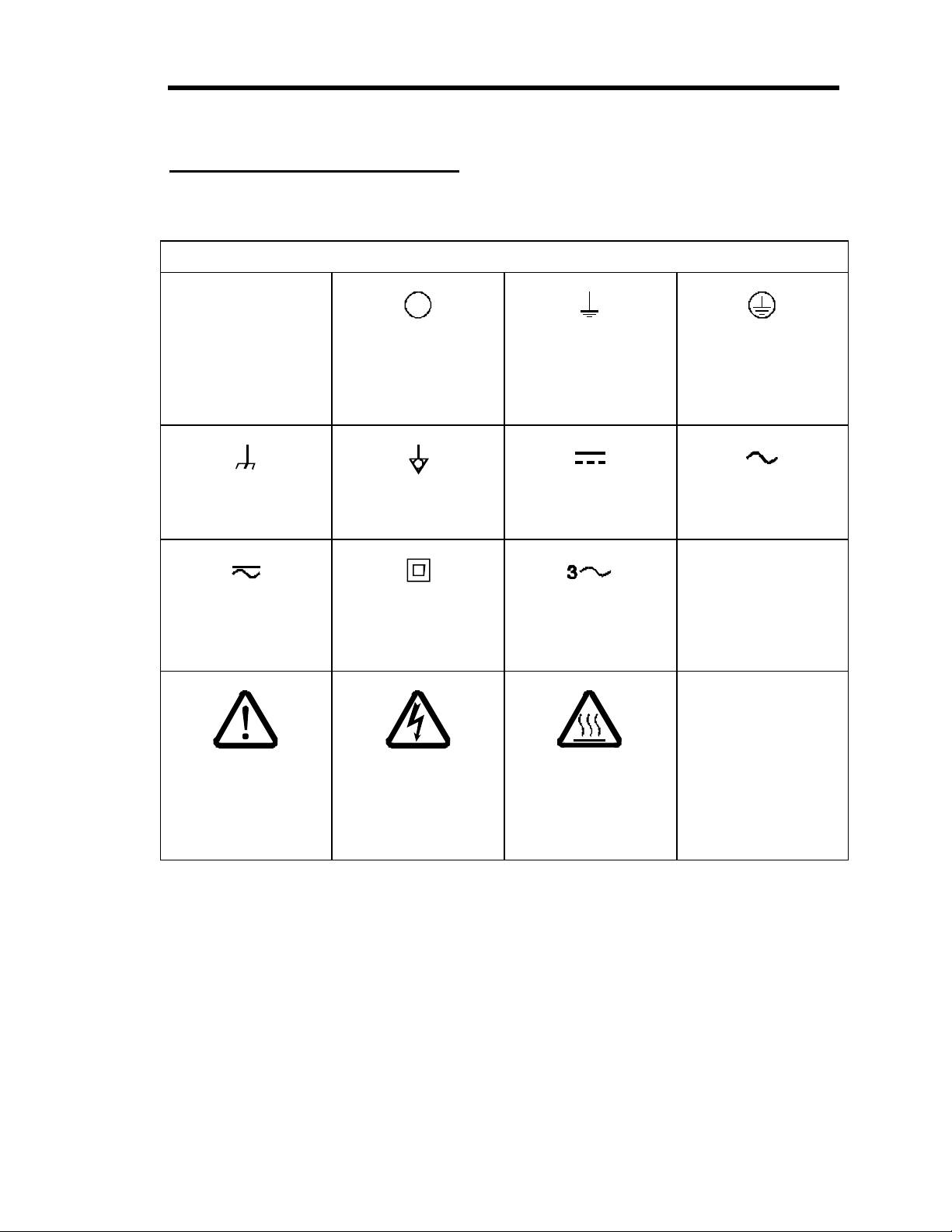
The following table describes symbols that may be found on the unit.
Definition of Symbols Found on the Unit
|
Protective earth
On (Supply)
IEC 417, No.5007
Off (Supply)
IEC 417, No.5008
Earth (ground)
IEC 417, No.5017
(ground)
Frame or chassis
IEC 417, No.5020
Equipotentiality
IEC 417, No.5021
Class ll equipment
IEC 417, No.5172-a
Direct current
IEC 417, No.5031
Caution, hot surface
IEC 417, No.5041
Table 1: Definition of Symbols Found on the Unit
3

Safety Procedures and Precautions Pressure Transducer Safety Information
Safety Procedures and Precautions
Observe the following general safety precautions during all phases of operation of this
instrument. Failure to comply with these precautions or with specific warnings elsewhere in
this manual violates safety standards of intended use of the instrument and may impair the
protection provided by the equipment. MKS Instruments, Inc. assumes no liability for the
customer’s failure to comply with these requirements.
DO NOT SUBSTITUTE PARTS OR MODIFY INSTRUMENT
Do not install substitute parts or perform any unauthorized modification to the instrument. Return
the instrument to an MKS Calibration and Service Center for service and repair to ensure that all
safety features are maintained.
SERVICE BY QUALIFIED PERSONNEL ONLY
Operating personnel must not attempt component replacement and internal adjustments. Any
service must be made by qualified service personnel only.
USE CAUTION WHEN OPERATING WITH HAZARDOUS MATERIALS
If hazardous materials are used, users must take responsibility to observe the proper safety
precautions, completely purge the instrument when necessary, and ensure that the material used is
compatible with the materials in this product, including any sealing materials.
PURGE THE INSTRUMENT
After installing the unit, or before removing it from a system, purge the unit completely with a
clean, dry gas to eliminate all traces of the previously used flow material.
USE PROPER PROCEDURES WHEN PURGING
This instrument must be purged under a ventilation hood, and gloves must be worn for protection.
DO NOT OPERATE IN AN EXPLOSIVE ENVIRONMENT
To avoid explosion, do not operate this product in an explosive environment unless it has been
specifically certified for such operation.
USE PROPER FITTINGS AND TIGHTENING PROCEDURES
All instrument fittings must be consistent with instrument specifications, and compatible with the
intended use of the instrument. Assemble and tighten fittings according to manufacturer’s
directions.
4

Pressure Transducer Safety Information Safety Procedures and Precautions
CHECK FOR LEAK-TIGHT FITTINGS
Carefully check all vacuum component connections to ensure leak-tight installation.
OPERATE AT SAFE INLET PRESSURES
Never operate at pressures higher than the rated maximum pressure (refer to the product
specifications for the maximum allowable pressure).
INSTALL A SUITABLE BURST DISC
When operating from a pressurized gas source, install a suitable burst disc in the vacuum system
to prevent system explosion should the system pressure rise.
KEEP THE UNIT FREE OF CONTAMINANTS
Do not allow contaminants to enter the unit before or during use. Contamination such as dust, dirt,
lint, glass chips, and metal chips may permanently damage the unit or contaminate the process.
ALLOW PROPER WARM UP TIME FOR TEMPERATURE-CONTROLLED UNITS
Temperature-controlled units will only meet specifications when sufficient time is allowed for the
unit to meet, and stabilize at, the designed operating temperature. Do not zero or calibrate the unit
until the warm up is complete.
5
In dieser Betriebsanleitung vorkommende Symbole Sicherheitshinweise für den Druckmeßumformer
Sicherheitshinweise für den Druckmeßumformer
In dieser Betriebsanleitung vorkommende Symbole
Bedeutung der mit WARNUNG!, VORSICHT! und HINWEIS gekennzeichneten Absätze in
dieser Betriebsanleitung.
Warnung!
Das Symbol WARNUNG! weist auf eine Gefahr für das
Bedienpersonal hin. Es macht auf einen Arbeitsablauf, eine
Arbeitsweise, einen Zustand oder eine sonstige Gegebenheit
aufmerksam, deren unsachgemäße Ausführung bzw.
ungenügende Berücksichtigung zu Verletzungen führen
kann.
Vorsicht! Das Symbol VORSICHT! weist auf eine Gefahr für das Gerät hin.
Es macht auf einen Bedienungsablauf, eine Arbeitsweise oder eine
sonstige Gegebenheit aufmerksam, deren unsachgemäße
Ausführung bzw. ungenügende Berücksichtigung zu einer
Beschädigung oder Zerstörung des Gerätes oder von Teilen des
Gerätes führen kann.
Hinweis
Das Symbol HINWEIS macht auf wichtige Informationen bezüglich eines
Arbeitsablaufs, einer Arbeitsweise, eines Zustands oder einer sonstige
Gegebenheit aufmerksam.
6
Sicherheitshinweise für den Druckmeßumformer Erklärung der am Gerät angebrachten Symbole
Erklärung der am Gerät angebrachten Symbole
Nachstehender Tabelle sind die Bedeutungen der Symbole zu entnehmen, die am Gerät
angebracht sein können.
Bedeutung der am Gerät angebrachten Symbole
|
Ein (Energie)
IEC 417, No.5007
Masseanschluß
IEC 417, No.5020
Gleich- oder
Wechselstrom
IEC 417, No.5033-a
Warnung vor einer
Gefahrenstelle
(Achtung, Dokumen-
tation beachten)
ISO 3864, No.B.3.1
Aus (Energie)
IEC 417, No.5008
Aquipotential-anschluß
IEC 417, No.5021 Gleichstrom
Durchgängige doppelte
oder verstärkte
Isolierung
IEC 417, No.5172-a
Warnung vor
gefährlicher
elektrischer Spannung
ISO 3864, No.B.3.6
Erdanschluß
IEC 417, No.5017
IEC 417, No.5031
Dreileiter-
Wechselstrom
(Drehstrom)
IEC 617-2, No.020206
Höhere Temperatur an
leicht
zugänglichen Teilen
IEC 417, No.5041
Schutzleiteranschluß
IEC 417, No.5019
Wechselstrom
IEC 417, No.5032
Tabelle 2: Bedeutung der am Gerät angebrachten Symbole
7

Sicherheitsvorschriften und Vorsichtsmaßnahmen Sicherheitshinweise für den Druckmeßumformer
Sicherheitsvorschriften und Vorsichtsmaßnahmen
Folgende allgemeine Sicherheitsvorschriften sind während allen Betriebsphasen dieses
Gerätes zu befolgen. Eine Mißachtung der Sicherheitsvorschriften und sonstiger
Warnhinweise in dieser Betriebsanleitung verletzt die für dieses Gerät und seine Bedienung
geltenden Sicherheitsstandards, und kann die Schutzvorrichtungen an diesem Gerät
wirkungslos machen. MKS Instruments, Inc. haftet nicht für Mißachtung dieser
Sicherheitsvorschriften seitens des Kunden.
Niemals Teile austauschen oder Änderungen am Gerät vornehmen!
Ersetzen Sie keine Teile mit baugleichen oder ähnlichen Teilen, und nehmen Sie keine
eigenmächtigen Änderungen am Gerät vor. Schicken Sie das Gerät zwecks Wartung und
Reparatur an den MKS-Kalibrierungs- und -Kundendienst ein. Nur so wird sichergestellt, daß alle
Schutzvorrichtungen voll funktionsfähig bleiben.
Wartung nur durch qualifizierte Fachleute!
Das Auswechseln von Komponenten und das Vornehmen von internen Einstellungen darf nur von
qualifizierten Fachleuten durchgeführt werden, niemals vom Bedienpersonal.
Vorsicht beim Arbeiten mit gefährlichen Stoffen!
Wenn gefährliche Stoffe verwendet werden, muß der Bediener die entsprechenden
Sicherheitsvorschriften genauestens einhalten, das Gerät, falls erforderlich, vollständig spülen,
sowie sicherstellen, daß der Gefahrstoff die am Gerät verwendeten Materialien, insbesondere
Dichtungen, nicht angreift.
Spülen des Gerätes mit Gas!
Nach dem Installieren oder vor dem Ausbau aus einem System muß das Gerät unter Einsatz eines
reinen Trockengases vollständig gespült werden, um alle Rückstände des Vorgängermediums zu
entfernen.
Anweisungen zum Spülen des Gerätes
Das Gerät darf nur unter einer Ablufthaube gespült werden. Schutzhandschuhe sind zu tragen.
Gerät nicht zusammen mit explosiven Stoffen, Gasen oder Dämpfen benutzen!
Um der Gefahr einer Explosion vorzubeugen, darf dieses Gerät niemals zusammen mit (oder in
der Nähe von) explosiven Stoffen aller Art eingesetzt werden, sofern es nicht ausdrücklich für
diesen Zweck zugelassen ist.
8

Sicherheitshinweise für den Druckmeßumformer Sicherheitsvorschriften und Vorsichtsmaßnahmen
Anweisungen zum Installieren der Armaturen!
Alle Anschlußstücke und Armaturenteile müssen mit der Gerätespezifikation übereinstimmen, und
mit dem geplanten Einsatz des Gerätes kompatibel sein. Der Einbau, insbesondere das Anziehen
und Abdichten, muß gemäß den Anweisungen des Herstellers vorgenommen werden.
Verbindungen auf Undichtigkeiten prüfen!
Überprüfen Sie sorgfältig alle Verbindungen der Vakuumkomponenten auf undichte Stellen.
Gerät nur unter zulässigen Anschlußdrücken betreiben!
Betreiben Sie das Gerät niemals unter Drücken, die den maximal zulässigen Druck (siehe
Produktspezifikationen) übersteigen.
Geeignete Berstscheibe installieren!
Wenn mit einer unter Druck stehenden Gasquelle gearbeitet wird, sollte eine geeignete
Berstscheibe in das Vakuumsystem installiert werden, um eine Explosionsgefahr aufgrund von
steigendem Systemdruck zu vermeiden.
Verunreinigungen im Gerät vermeiden!
Stellen Sie sicher, daß Verunreinigungen jeglicher Art weder vor dem Einsatz noch während des
Betriebs in das Instrumenteninnere gelangen können. Staub- und Schmutzpartikel, Glassplitter
oder Metallspäne können das Gerät dauerhaft beschädigen oder Prozeß und Meßwerte
verfälschen.
Bei Geräten mit Temperaturkontrolle korrekte Anwärmzeit einhalten!
Temperaturkontrollierte Geräte arbeiten nur dann gemäß ihrer Spezifikation, wenn genügend Zeit
zum Erreichen und Stabilisieren der Betriebstemperatur eingeräumt wird. Kalibrierungen und
Nulleinstellungen sollten daher nur nach Abschluß des Anwärmvorgangs durchgeführt werden.
9

Symboles utilisés dans ce manuel d'utilisation Informations relatives à la sécurité pour le
transducteur de pression
Informations relatives à la sécurité pour le transducteur
de pression
Symboles utilisés dans ce manuel d'utilisation
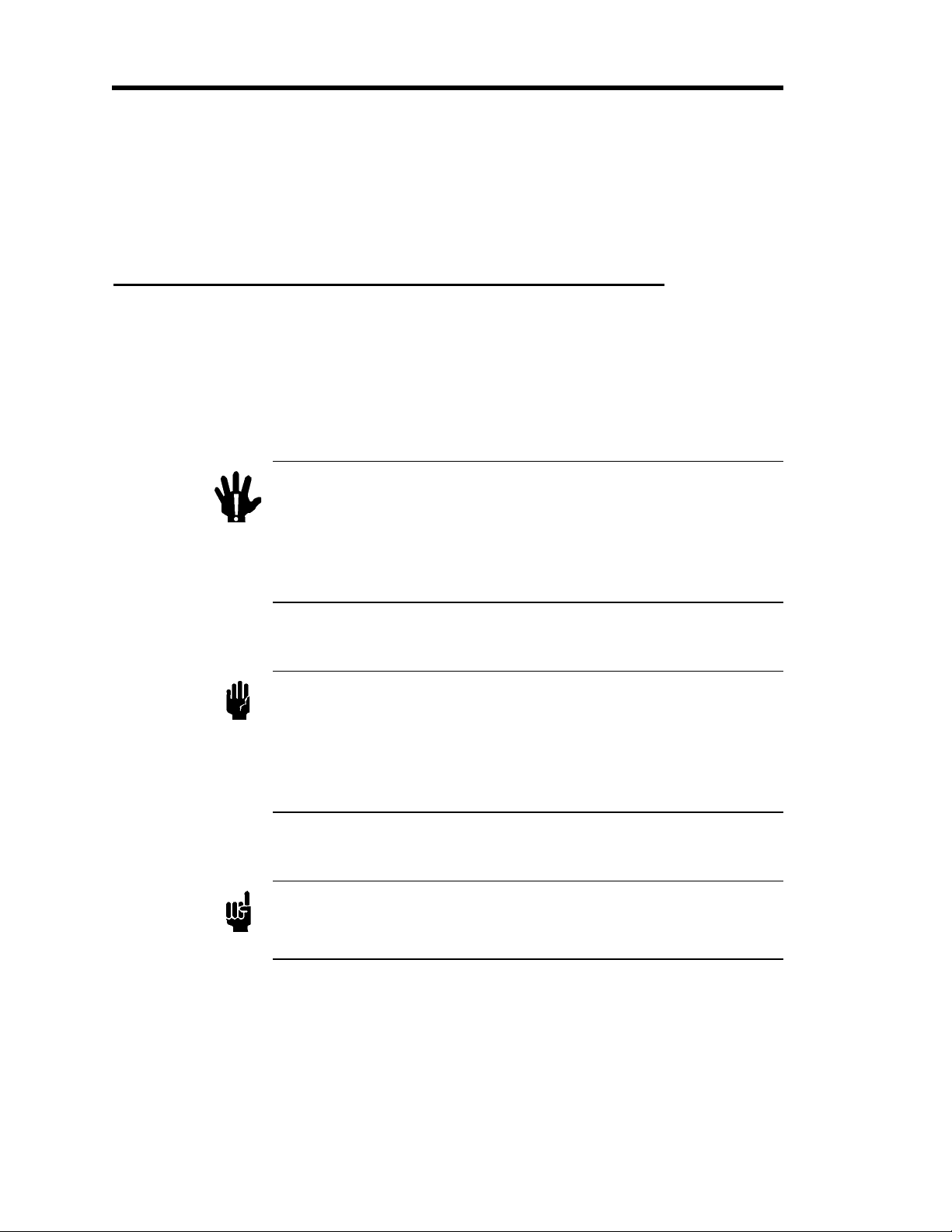
Définitions des indications AVERTISSEMENT, ATTENTION, et REMARQUE utilisées dans ce
manuel.
Avertissement
Attention L'indication ATTENTION signale un danger pour l'appareil.
Remarque
L'indication AVERTISSEMENT signale un danger pour le
personnel. Elle attire l'attention sur une procédure, une
pratique, une condition, ou toute autre situation
présentant un risque d'accident pour le personnel, en
cas d'exécution incorrecte ou de non respect des
consignes.
Elle attire l'attention sur une procédure d'exploitation, une
pratique, ou toute autre situation, présentant un risque
d'endommagement ou de destruction d'une partie ou de la
totalité de l'appareil, en cas d'exécution incorrecte ou de non
respect des consignes.
L'indication REMARQUE signale une information importante. Elle
attire l'attention sur une procédure, une pratique, une condition, ou
toute autre situation, présentant un intérêt particulier.
10
Informations relatives à la sécurité pour le
transducteur de pression
Symboles apparaissant sur l'unité
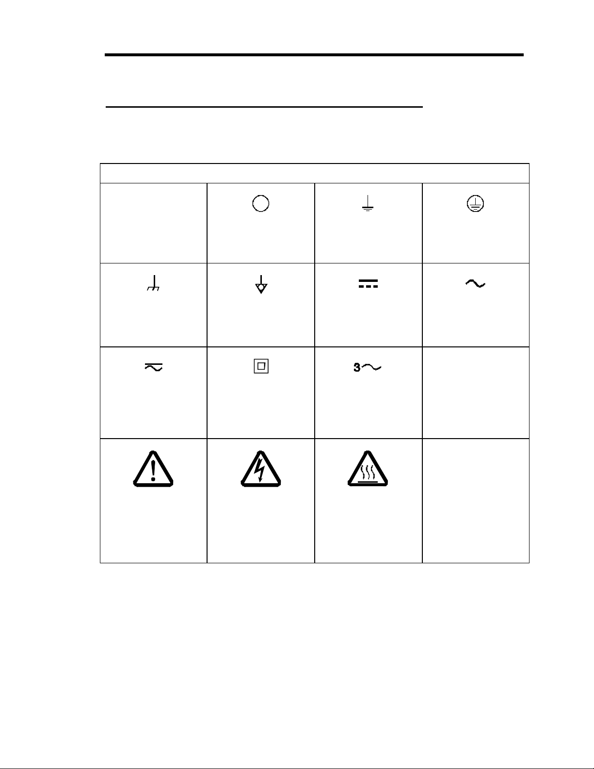
Le tableau suivant décrit les symboles pouvant apparaître sur l'unité.
Définition des symboles apparaissant sur l'unité
|
Symboles apparaissant sur l'unité
Marche
(sous tension)
IEC 417, No.5007
Masse
IEC 417, No.5020
Courant continu et
alternatif
IEC 417, No.5033-a
Attention : se reporter
à la documentation
ISO 3864, No.B.3.1
Arrêt (hors tension)
IEC 417, No.5008
Equipotentialité
IEC 417, No.5021
Matériel de classe II
IEC 417, No.5172-a
Attention : risque de
choc électrique
ISO 3864, No.B.3.6
Terre (masse)
IEC 417, No.5017
Courant continu
IEC 417, No.5031
Courant alternatif
triphasé
IEC 617-2, No.020206
Attention : surface
brûlante
IEC 417, No.5041
Terre de protection
(masse)
IEC 417, No.5019
Courant alternatif
IEC 417, No.5032
Tableau 3: Définition des symboles apparaissant sur l'unité
11
 Loading...