

MKS Mass-Flo 1179A, Mass-Flo 179A, Mass-Flo 2179A Instruction Manual

MKS Type 1179A and 2179A
116527-P1
Rev E, 3/99
Instruction Manual
Mass-Flo® Controller
and
Type 179A Mass-Flo Meter
Six S hatt uck Road
Andover, MA 01810-2449
(800) 227-8766 or (978) 975-2350
Fax: (978) 975-0093
E-mai l: mk s@mksinst.com
Web site: http://www.mksinst.com

WARRANTY
Type 1179A/2179A/179A Equipment
MKS Instruments, Inc. (
equip ment d escrib ed above ( the “equ ipment ”) manu fact ured by
defects in materials and workmanship and will correctly perform all date-related
operations, including without limitation accepting data entry, sequencing, sorting,
compa ring, a nd repor ting, r egardl ess of t he date t he oper ation i s perfo rmed or t he date
invo lved in the ope rat ion, prov ide d that , if th e equip ment exc hange s data or is ot herw ise
used with equipment, software, or other products of others, such products of others
them selves co r r ectly perform all date - related opera tions and store a nd trans mit date s a nd
date-relate d data in a format compatible with
MKS’
SOLE WARRANTY CONCERNING DATE-RELATED OPERATIONS.
For th e per io d comme nc ing w ith the da te of shi pmen t of t hi s equ ip ment an d end in g th ree
years later,
mate rial s or workm anshi p or wit h resp ect to th e date- rela ted op erat ions wa rrant y with out
charg e t o th e pur cha s er. T he fore go in g sh al l co ns tit ut e t he exc lu si ve a nd s ol e reme dy of
the purcha ser for any bre ach by
The purchaser, before returning any equipment covered by this warranty, which is
ass ert ed t o be de fect i ve b y t he pu rch ase r, s ha ll mak e s peci f ic w ri tte n arr ang eme nts w ith
respe c t to t he re s pons ib il ity fo r sh ip pi ng t he eq ui pmen t an d ha nd li ng a ny ot her inc id en ta l
charges with the
purch ased or, in the ca se of a di rect pur chase f rom
Andover, M assachuse tts, USA.
This wa r ran ty d oes not app ly to a ny eq ui pme nt wh ic h h as not be en i nst all ed an d us ed in
acc ord anc e wit h th e s peci fi cat io ns rec omme nd ed by
of the equipment.
consequential, or incidental damages in connection with, or arising out of, the sale,
performance, or use of the equipment covered by this warranty.
MKS
MKS
) warra nt s t hat f or thre e y ear s f rom t he d ate of shi pm ent the
MKS
shall be f ree fro m
MKS
equipment. THIS WARRANTY IS
will, at its opti on, ei th er repa ir o r repl ace any part whi ch is defec tiv e in
MKS
of this warranty.
MKS
sales rep rese ntati ve o r di strib utor from whic h th e eq uipmen t was
MKS
, with the
MKS
for the prop er and no rmal us e
MKS
shall no t be liabl e under any circums tances for indi rect, special ,
MKS
home of fice in
MKS
recommends that all
(ty pi c ally every 6 to 12 months ) to ensur e accurate read i ngs. Wh en a product is returned
MKS
to
for th is peri odic re -cali brati on it is consi dered normal preven tative mainte nance
not covered by any warr anty.
THIS WARRANTY IS IN LIEU OF ALL OTHER RELEVANT WARRANTIES,
EXPRESSED OR IMPLIED, INCLUDING THE IMPLIED WARRANTY OF
MERCHANTABILITY AND THE IMPLIED WARRANTY OF FITNESS FOR A
PARTICULAR PURPOSE, AND ANY WARRANTY AGAI NST INFRINGEMENT OF ANY
PATENT.
MKS
pressure and flow products be calibrated periodically
11-98 116527-P1

MKS Type 1179A and 2179A
Mass-Flo® Controller
116527-P1
Rev E, 3/99
and
Type 179A Mass-Flo Meter

Copyright © 1999 by MKS Instruments, Inc.
All rights reserved. No part of this work may be reproduced or transmitted in any form or by
any means, electronic or mechanical, including photocopying and recording, or by any
informa t i o n s t o r a g e or r et r ieval system, except as may be exp r es s l y per m itted in writing by MKS
Instruments, Inc.
Printed in the United States of America
Mass-Flo
Swagelok
®
is a registered trademark of MKS Instruments, Inc., Andover, MA
®
, VCR®, and VCO® are registered t rad em ark s o f Swagelok Marketing Com p an y,
Solon, OH
®
Kalrez
and Viton® are registered trademarks of DuPont Dow Elastomers Inc., Wilmington,
DE
NUPRO
Kel-F
®
is a registered trademark of Crawford Fitting Company, Solon, OH
®
is a regist ered trademark of 3M, Minneapo l i s , MN
DeviceNet is a trademark of Open DeviceNet Vendor Association, Inc., Coral Springs, FL
Protected by U.S. Patent 5,461,913; foreign patents pending

Table of Contents
Table of Contents
Mass Flow Controller Safety Information............................................................................... 1
Symbols Used in This Instruction Manual..................................................................1
Symbols Found on the Unit ....................................................................................... 2
Safety Pr oced u res an d Precautions ............................................................................. 3
Sicherheitshinweise für den Massenflußregler........................................................................5
In dieser Betriebsanleitung vorkommende Symbole................................................... 5
Erklärung der am Gerät angebrachten Symbole.......................................................... 6
Sicherheitsvorschriften und Vorsichtsmaßnahmen......................................................7
Information s rel at i v es à la sécurité pour le contrôleur de débit de masse................................. 9
Symboles utilisés dans ce manuel d'utilisation........................................................... 9
Symboles apparaissant sur l'unité............................................................................... 10
Mesures de sécurité et précautions............................................................................. 11
Medidas de seguridad del controlador de flujo de masa .......................................................... 13
Símbolos usados en este manual de instrucciones.......................................................13
Símbolos hallados en la unidad.................................................................................. 14
Procedimientos y precauciones d e s eg u ri d ad .............................................................. 15
Chapter One: General Information......................................................................................... 17
Introduction............................................................................................................... 17
Design Features............................................................................................. 17
Reliability..................................................................................................... 18
Cleanliness Features...................................................................................... 18
How This Manual is Organized.................................................................................. 19
Customer Support...................................................................................................... 20
Chapter Two: Installation......................................................................................................21
How To Unpack the Type 1179 Series Unit............................................................... 21
Opening the Package..................................................................................... 21
Unpacking Checklist .................................................................................................. 22
Environmental Requirements..................................................................................... 23
iii

Table of Contents
Interface Cables..........................................................................................................24
Generic Shielded Cable Description...............................................................25
Setup..........................................................................................................................26
Dimensions.................................................................................................... 27
Gas Line Connections ................................................................................................29
Standard Fittings............................................................................................29
Optional Fittings............................................................................................29
Mounting a Type 1179 MFC......................................................................................29
Mounting a Type 2179 MFC......................................................................................30
Chapter Three: Overview.......................................................................................................31
Type 2179 MFC with a Positive Shutoff Valve..........................................................31
Electrical Connections................................................................................................31
9-Pin Type “D” Connector.............................................................................32
P.C. Edge Card Connector............................................................................. 33
15-Pin Type “D” Connector...........................................................................34
The Gas Correction Factor (GCF)...............................................................................35
How To Calculate the GCF for Pure Gases....................................................35
How To Calculate the GCF for Gas Mixtures.................................................36
How To Read Mass Flow at a Different Reference Temperature....................37
Labels ........................................................................................................................ 38
Control Valve (MFC only).........................................................................................38
Chapter Four: Operation........................................................................................................39
How To Start Up the MFC/MFM...............................................................................39
How To Zero the Flow Controller..............................................................................40
How To Adjust the Controller Gain (MFC only)........................................................41
How To Override the Valve (MFC only)....................................................................42
Priority of the Commands..............................................................................42
How To Use the Optional Input (MFC only)..............................................................43
Chapter Five: Theory of Operation......................................................................................... 45
General Information...................................................................................................45
Flow Path................................................................................................................... 45
Measurement Technique.............................................................................................45
iv

Table of Contents
Control Circuitry ....................................................................................................... 46
Chapter Six: Maintenance...................................................................................................... 47
General...................................................................................................................... 47
Zero Adjustment........................................................................................................ 47
Repair........................................................................................................................ 48
Chapter Seven: Troubleshooting............................................................................................ 49
Troubleshooting Chart............................................................................................... 49
How To Adjust the Valve Preload (MFC only).......................................................... 50
Appendix A: Product Specifications...................................................................................... 57
Performance Specifications........................................................................................ 57
Environmental Specifications.....................................................................................58
Electrical Specifications............................................................................................. 58
Physical Specifications.............................................................................................. 59
Appendix B: Model Code Explanation.................................................................................. 61
Model Code............................................................................................................... 61
Appendix C: Gas Correction Factors ..................................................................................... 65
Common Gases..........................................................................................................65
Appendix D: MFC Sizing Guidelines.................................................................................... 69
General Information................................................................................................... 69
How To Determine the Flow Controller Range.......................................................... 70
How To Determine the Valve Configuration.............................................................. 71
Example........................................................................................................ 73
Appendix E: Positive Shutoff Valve Information ................................................................... 75
How To Operate the Positive Shutoff Valve............................................................... 75
Index...................................................................................................................................... 77
v

Table of Contents
vi

List of Figures and Tables
List of Figures and Tables
Figures
Figure 1: Outline Dimensions of the Type 1179 MFC and Type 179 MFM........................... 27
Figure 2: Side View of the Type 1179 MFC and Type 179 MFM.......................................... 28
Figure 3: Outline Dimensions of the Type 2179 MFC (with optional mounting plate)........... 28
Figure 4: Mounting Dimensions of the 1179 Flow Controller................................................ 29
Figure 5: Mounting Dimensions of the Base Aluminum Plate ............................................... 30
Figure 6: Mounting Dimensions of the Type 2179 Flow Controller....................................... 30
Figure 7: Serial Number Label .............................................................................................. 38
Figure 8: Location of the Retaining Screws........................................................................... 51
Figure 9: Location of the Lock Nut and Centershaft .............................................................. 52
Figure 10: Location of the R85 Potentiometer on the PC Board............................................. 55
Figure 11: Connecting the Type 2179 MFC to a Solenoid Valve........................................... 76
Tables
Table 1: Definition of Symbols Found on the Unit.....................................................................2
Tabelle 2: Bedeutung der am Gerät angebrachten Symbole.........................................................6
Tableau 3: Définition des symboles apparaissant sur l'unité......................................................10
Tabla 4: Definición de los símbolos hallados en la unidad........................................................14
Table 5: MKS Cables............................................................................................................... 24
Table 6: 9-Pin Type “D” Connector Pinout...............................................................................32
Table 7: 20-Pin Edge Card Connector Pinout ...........................................................................33
Table 8: 15-Pin Type “D” Connector Pinout.............................................................................34
Table 9: Troubleshooting Chart................................................................................................ 49
Table 10: Maximum Valve Currents.........................................................................................54
Table 11: Valve Current Headroom..........................................................................................54
Table 12: Cv Pressure Factors..................................................................................................71
Table 13: Valve Configuration Selection Guide........................................................................72
Table 14: Suitable Two-Way Solenoid Valves..........................................................................75
vii

List of Figures and Tables
viii
Mass Flow Controller Safety Information Symbols Used in This Instruction Manual
Mass Flow Controller Safety Information
Symbols Used in This Instruction Manual
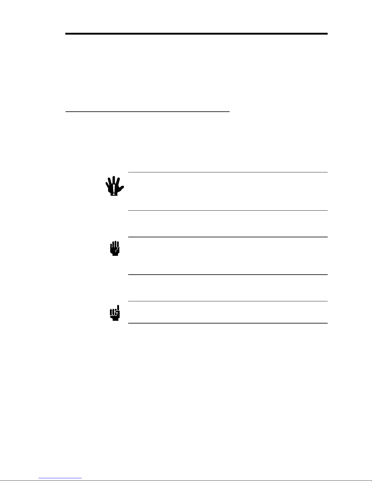
Definitions of WARNING, CAUTION, and NOTE messages used throughout the manual.
Warning
Caution
Note
The WARNING sign denote s a hazard to personnel. It call s
attention to a procedure, practice , condition, or the like,
which, if not correctly performed or adhered to, c ould result
in injury to personnel .
The CAUTION s i gn denotes a hazard to eq uipment. I t call s
attention to an operatin g p ro ced ure, practice, or the lik e, which, i f
not correctly performed or adhered to, cou l d result in damage to or
destruction of all or part of the product.
The NOTE sign denotes important information. It calls attention to a
procedure, practice, condition, or the like, which is essential to highlight.
1
Symbols Found on the Unit Mass Flow Controller Safety Information
g
g
g
g
g
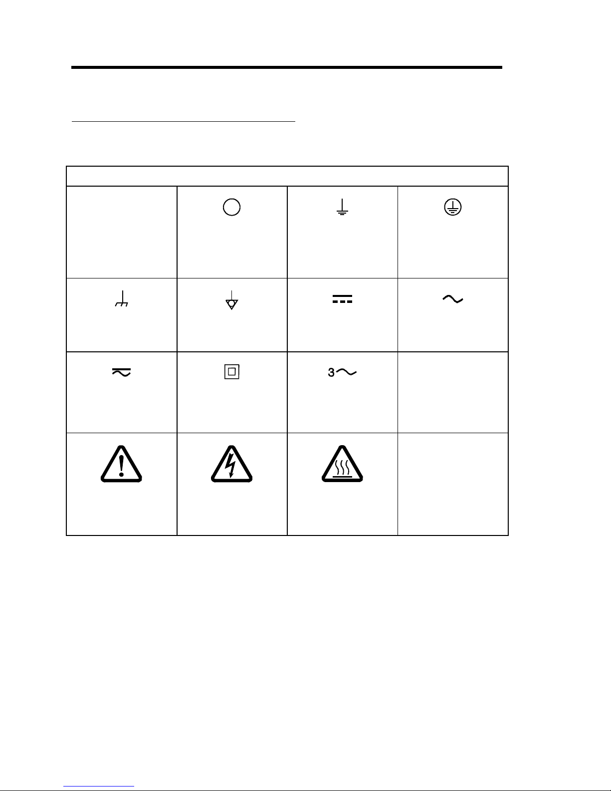
Symbols Found on the Unit
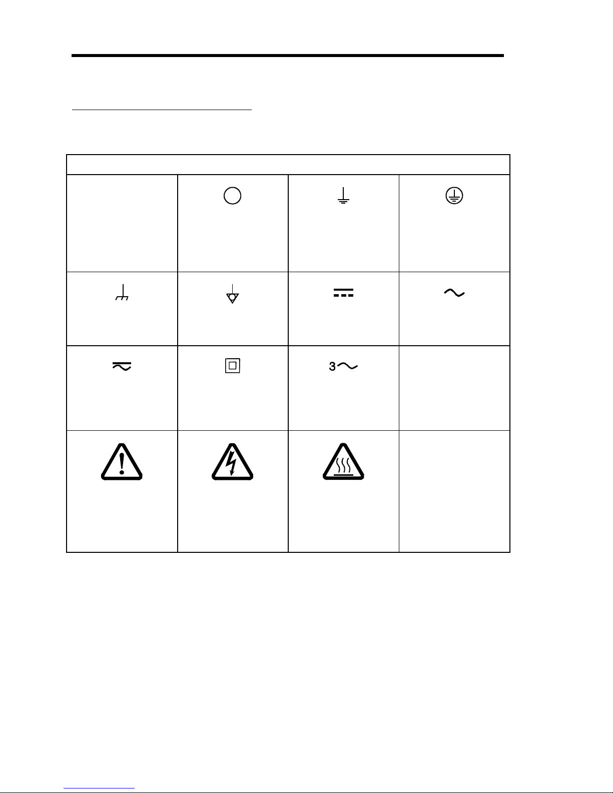
The following table describes symbols that may be found on the unit.
Definition of Symbols Found on the Unit
|
Protective earth
round)
On (Supply)
IEC 417, No.5007
Off (Supply)
IEC 417, No.5008
Earth (
IEC 417, No.5017
round)
(
IEC 417, No.5019
Frame or chassis
IEC 417, No.5020
Both direct and
alternatin
IEC 417, No.5033-a
Caution, refer to
accompanyin
ISO 3864, No.B.3.1
current
documents
Equipotentiality
IEC 417, No.5021
Class ll equipment
IEC 417, No.5172-a
Caution, risk of
electric shock
ISO 3864, No.B.3.6
Direct current
IEC 417, No.5031
Three phase
alternating current
IEC 617-2 No.020206
Caution, hot surface
IEC 417, No.5041
Table 1: Definition of Symbols Found on the Unit
Alternatin
IEC 417, No.5032
current
2

Mass Flow Controller Safety Information Safety Procedures and Precautions
Safety Procedures and Precautions
The foll o wi n g g en era l s a fety p reca utions mu s t be observed during a l l p hases of op era ti o n o f this
instrument. Failure to comply wi th these precauti o n s o r wi th specific warnings els ewhere in
this manual violates safety standards of intended use of the instrument and may impair the
protection provided by the equipment. MKS Instruments, Inc. assumes no liability for the
customer’s fai l ure to comply wi th these requirements.
DO NOT SUBSTITUTE PARTS OR MODIFY INSTRUMENT
Do not install substitute parts or perform any unauthorized modification to the instrument.
Return the instrument to an MKS Calibration and Service Center for service and repair to ensure
that all safety features are maintained.
SERVICE BY Q UAL IFI E D PE RS O NNE L O NL Y
Operating personnel must not at t empt com ponent replacem ent and i nt ernal adj us tm ent s. Any
service must be made by qualified service personnel only.
USE CAUTION WHE N O PE RAT I NG WIT H H AZ ARDOUS MATERIALS
If hazardous materials are used, obs erve t he proper s afety precauti ons , com p let ely purge t he
instrument when necessary, and ensure that the material used is compatible with the wetted
materials in this product, including any sealing materials.
PURGE THE INSTRUMENT
After installing the unit, or before removing it from a system, purge the unit completely with a
clean, dry gas to eliminate all traces of the previou s l y u s ed flow material.
USE PROPER PROCEDURE S WHEN PURGING
This instrument must be purged under a ventilation hood, and gloves must be worn for
protection.
DO NOT OPERAT E I N AN E XPL O S IVE ENVIRONMENT
To avoid explosion, do not operate this product in an explosive environment unless it has been
specificall y cert i f i ed fo r s u ch op erat i o n .
USE PROPER FIT T ING S AND T I G H T E NING PRO CE DURE S
All instrument fittings must be consistent with instrument specifications, and compatible with the
intended use of the instrument. Assemble and tighten fittings according t o m an u fact u rer’s
directions.
3

Safety Procedures and Precautions Mass Flow Controller Safety Information
CHECK FOR LEAK-TIGHT FITTINGS
Carefully check all vacuum component connections to ensure leak-tight installation.
OPERATE AT SAFE INLET PRESSURES
Never operate at pressures higher than the rated maximum pressure (refer to the product
specifications for the maximum allowable pressure).
INSTALL A SUITABLE BURST DISC
When operating from a pressurized gas source, install a suitable burst disc in the vacuum system
to prevent system explosion should the system pressure rise.
KEEP THE UNI T FRE E O F CO NT AMI NANT S
Do not allow contaminants to enter the unit before or during use. Contamination such as dust,
dirt, lint, glass chips, and metal chips may permanently damage the unit or contaminate the
process.
ALLOW THE UNIT TO WARM UP
If the unit is used to control dangerous gases, they should not be applied before the unit has
completely warmed up. Use a positive shutoff valve to ensure that no erroneous flow can occur
during warm up.
4
Sicherheitshinweise für den Massenflußregler In dieser Betriebsanleitung vorkommende Symbole
Sicherheitshinweise für den Massenfl ußregler
In dieser Betriebsanleitung vorkommende Symbole
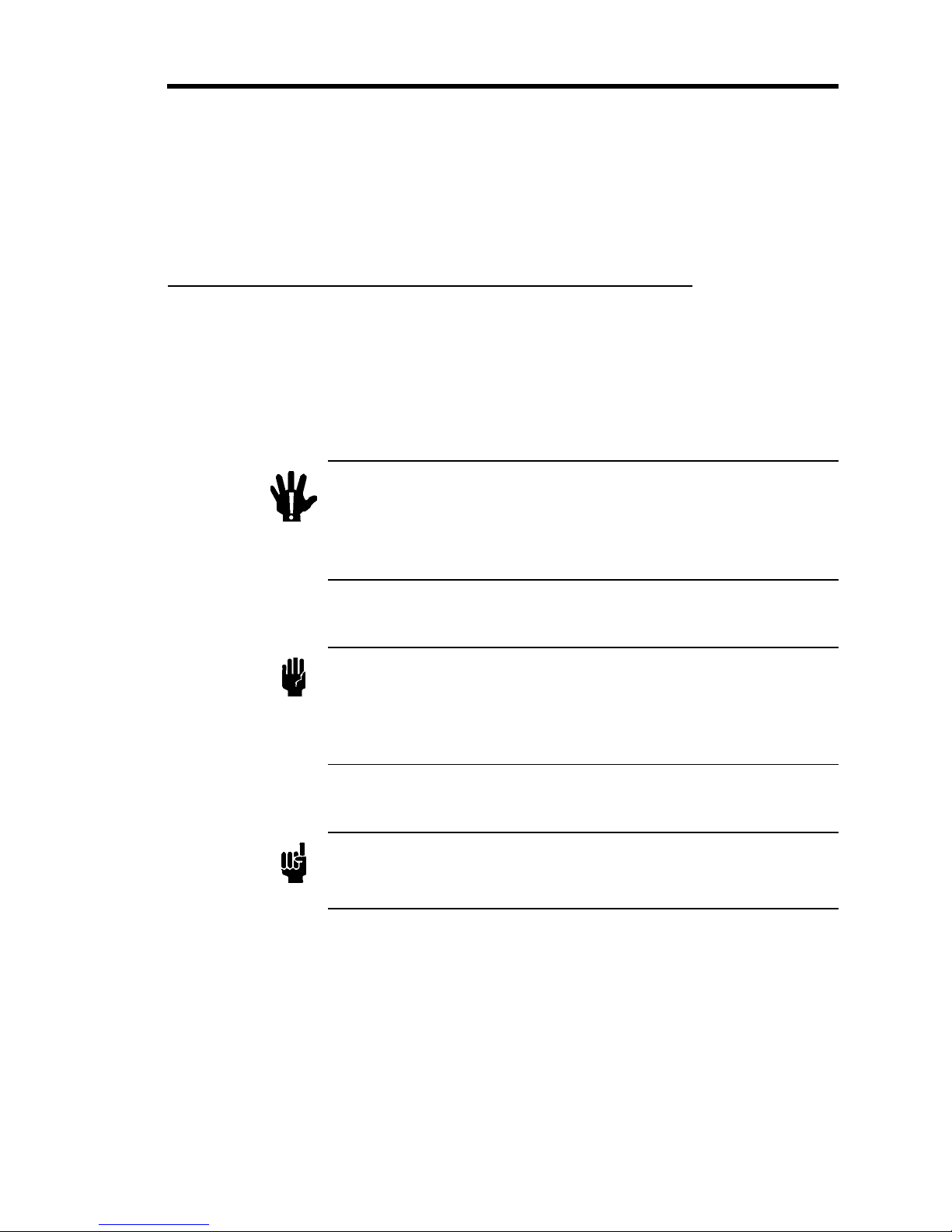
Bedeutung der mit WARNUNG!, VORSICHT! und HINWEIS gekennzeichneten Absätze in
dieser Betriebsanleitung.
Warnung!
Vorsicht!
Hinweis
Das Sym bol WARNUNG! weist a uf eine Gefahr für das
Bedienpersonal hin. Es macht auf einen Arbeitsa blauf, eine
Arbeitsweis e, einen Zustand oder eine sonstige Gegebenheit
aufmerksam, deren unsachgemäße Ausführung bzw.
ungenügende Berücksichtigung zu Verletzungen führen kann.
Das Symbol VORSICHT! weist auf ei n e G efah r für das Gerät hin. Es
macht auf einen Bedienungsablauf, eine Arbeitsweise oder eine
sonstig e G eg ebenheit au fmerksam, deren unsach g emäße Ausführung
bzw. ungenügende Berücksich tigung zu ei ner Beschädigung oder
Zerstörung des Gerätes oder von Teilen des Gerätes führen kann.
Das Symbol HINWEIS m acht auf wichtige Informationen bezüglich eines
Arbeitsablaufs, einer Arbeitsweise, eines Zustands oder einer sonstige
Gegebenheit aufmerksam.
5
Erklärung der am Gerät angebrac hte n Symbol e Sicherheitshinweise für den Massenflußregle
r
g
gäng
Erklärung der am Gerät angebrachten Symbole
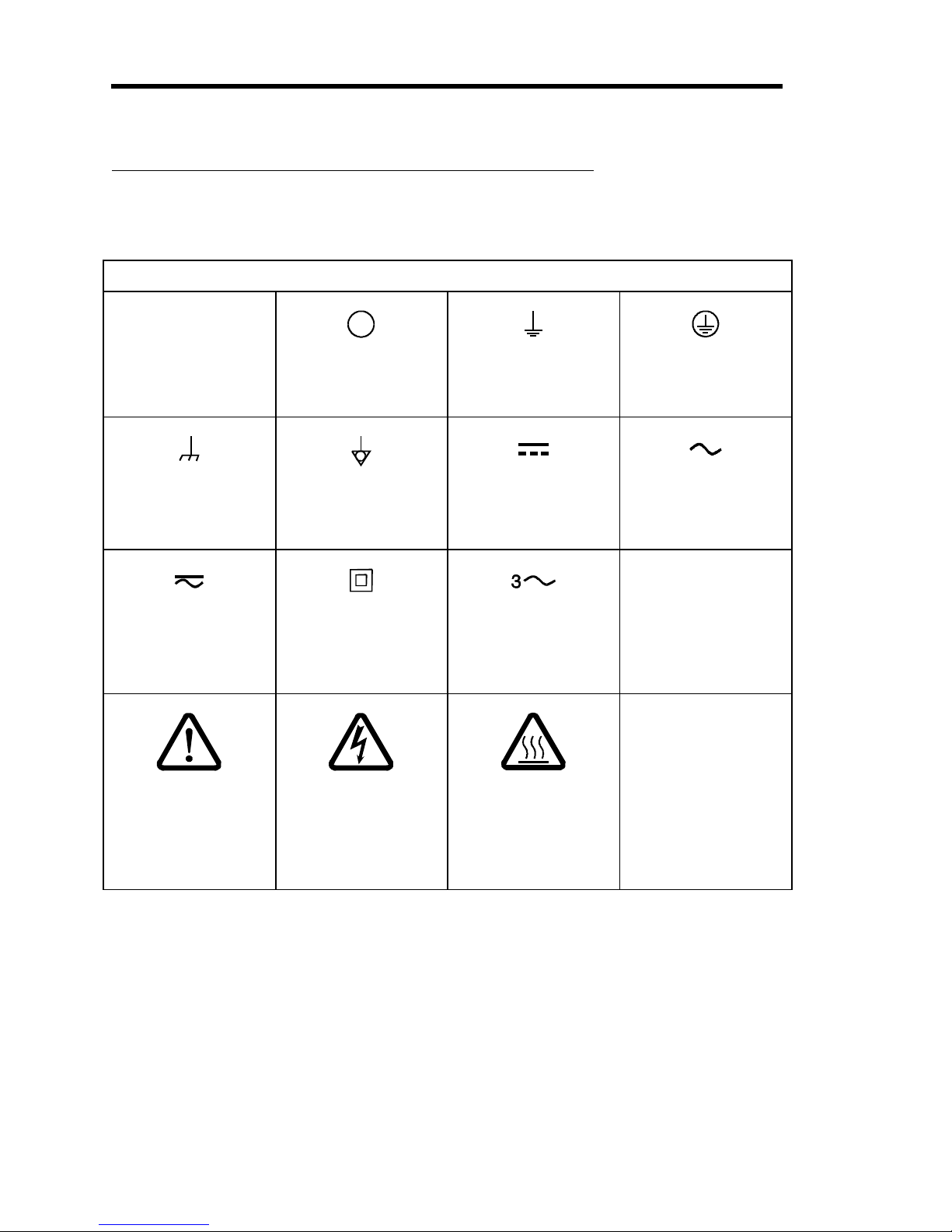
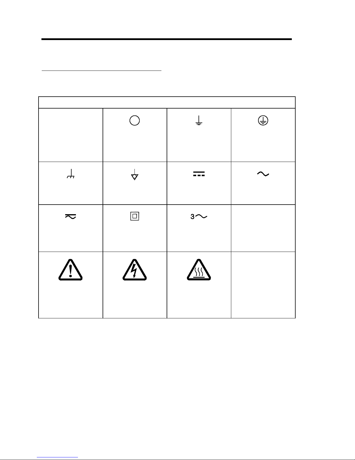
Nachstehender Tabelle sind die Bedeutungen der Symbole zu entnehmen, die am Gerät
angebracht sein können.
Bedeutung der am Gerät angebrachten Symbole
|
Ein (Energie)
IEC 417, No.5007
Mass eanschluß
IEC 417, No.5020
Gleich- oder
Wechselstrom
IEC 417, No.5033-a
Warnung vor einer
Gefahrenstelle
(Achtung, Dokumen-
tation beachten)
ISO 3864, No. B .3. 1
Aus (Energie)
IEC 417, No.5008
Aquipotential-
anschluß
IEC 417, No.5021
Durchgängige
doppelte oder
verstärkte Isolierung
IEC 417, No.5172-a
Warnung vor
gefährlicher
elektrischer Spannun
ISO 3864, No. B .3. 6
Erdanschluß
IEC 417, No.5017
Gleichstrom
IEC 417, No.5031
Dreileiter-
Wechselstrom
(Drehstrom)
IEC 617-2, No.020206
Höhere Temperatur
an leicht
zu
lichen Teilen
IEC 417, No.5041
Schutzleiteranschluß
IEC 417, No.5019
Wechselstrom
IEC 417, No.5032
Tabelle 2: Bedeutung der am Gerät angebrachten Symbole
6

Sicherheitshinweise für den Massenflußregl e r Sicherheitsvorschriften und Vorsichtsma ßnahmen
Sicherheitsvorschriften und Vorsichtsmaßnahmen
Folgende allgemeine Sicherheitsvorschriften sind während allen Betriebsphasen dieses Gerätes
zu befolg en. Ein e Mi ßachtung der Sicherheitsvorschriften und sonstiger Warnhinweise in
dieser Betri ebsanlei tung verletzt d i e f ür dieses Gerät und seine Bedienung geltenden
Sicherheitsstandards, und kann die Schutzvorrichtungen an diesem Gerät wirkungslos machen.
MKS Instruments, Inc. haftet nicht für Mißachtung dieser Sicherheitsvorschriften seitens des
Kunden.
Niemals Teile austauschen oder Änderungen am Gerät vornehmen!
Ersetzen Sie keine Teile mit baugleichen oder ähnlichen Teilen, und nehmen Sie keine
eigenmächtigen Änderungen am Gerät vor. Schicken Sie das Gerät zwecks Wartung und
Reparatur an den MKS-Kalibrierungs- und -Kundendienst ein. Nur so wird sichergestellt, daß
alle Schutzvorrichtungen voll funktionsfähig bleiben.
Wartung n ur durch qualifi zi erte F a ch leute!
Das Auswechseln von Komponenten und das Vornehmen von internen Einstellungen darf nur
von qualifizierten Fachleuten durchgeführt werden, niemals vom Bedienpersonal.
Vorsicht beim Arbeiten mit gefährlichen Stoffen!
Wenn gefährliche Stoffe verwendet werden, muß der Bediener die en t s p rech end en
Sicherheitsvorschriften genauestens einhalten, das Gerät, falls erforderlich, vollständig spülen,
sowie sich ers t el l en , d aß der Gefahrstoff die von ihm benetzten, am Gerät verwendeten
Materialien, insbesondere Dichtungen, nicht angreift.
Spülen des Gerätes mit Gas!
Nach dem Installieren oder vor dem Ausbau aus einem System muß das Gerät unter Einsatz ei n es
reinen Trockengases vollständig gespült werden, um alle Rückstände des Vorgängermediums zu
entfernen.
Anweisungen zum Spülen des Gerätes
Das Gerät darf nur unter einer Ablufthaube gespült werden. Schutzhandschuhe sind zu tragen.
Gerät nicht zusammen mit explosiven Stoffen, Gasen oder Dämpfen benutzen!
Um der Gefahr einer Explosion vorzubeugen, darf dieses Gerät niemals zusammen mit (oder in
der Nähe von) explosiven Stoffen aller Art eingesetzt werden, sofern es nicht ausdrücklich für
diesen Zweck zu g el as s en i s t .
7

Sicherheitsvorschriften und Vorsichtsma ßna hme n Sicherheitshinweise für den Massenflußregle
r
Anweisungen zum In s ta l l ieren der Armaturen!
Alle Anschlußstücke und Armaturenteile müssen mit der Gerätespezifikation übereinstimmen,
und mit dem geplanten Einsatz des Gerätes kompatibel sein. Der Einbau, insbesondere das
Anziehen und Abdichten, muß gemäß den Anweisungen des Herstellers vorgenommen werden.
Verbindungen auf Undichtigkeiten prüfen!
Überprüfen Sie sorgfältig alle Verbindungen der Vakuumkomponenten auf undichte Stellen.
Gerät nur unter zulässigen Anschlußdrücken betrei b en!
Betreiben Sie das Gerät niemals unter Drücken, die den max i m al zulässigen Druck (siehe
Produktspezifikationen) übersteigen.
Geeignete B ers ts cheibe in s ta l l ieren!
Wenn mit einer unter Druck stehenden Gasquelle gearbeitet wird, sollte eine geeignete
Berstscheibe in das Vakuumsystem installiert werden, um eine Explosionsgefahr aufgrund von
steigendem Systemdruck zu vermeiden.
Verunreinigungen im Gerät vermeiden!
Stellen Sie sicher, d aß Verunreinigungen jeglicher Art weder vor dem Einsatz noch während des
Betriebs in das Instrumenteninnere gelangen können. Staub- und Schmutzpartikel, Glassplitter
oder Metallspäne können das Gerät dauerhaft beschädigen oder Prozeß und Meßwerte
verfälschen.
Geräteeinheit auf Arbeitstemperatu r bringen!
Wird das Gerät zur Flußregelung gefährlicher Gase verwendet, so dürfen diese nur nach
Abschluß des Anwärmvorgangs zugeführt werden. Um das versehentliche Fließen von Gas
während der Aufheizperiode zu verhindern, sollte ein Absperrventil (normal geschlossen)
eingebaut werden.
8
Informations relative s à la sécurité pour le
contrôleur de débit de masse
Symboles utilisés dans ce manuel d'utilisation
Informations relatives à la sécurité pour le contrôleur de
débit de masse
Symboles utilisés dans ce manuel d'utilisation
Définitions des indications AVERTISSEMENT, ATTENTION, et REMARQUE utilisées dans
ce manuel.
Avertissement
Attention
Remarque
L'indication AVERTISSEMENT signale un danger pour le
personnel. El le attire l'attention sur une procédure, une
pratique, une condition, ou toute autre si tuation
présentant un risque d'accident pour le personnel, en
cas d'exécution incorrecte ou de non respect des
consignes.
L'indication ATTENTION signale un danger pour l'appareil.
Elle attire l'attention sur une procédure d'exploitation, une
pratique, ou toute autre situation, présentant un risque
d'endommagement ou de destruction d'une partie ou de la
totalité de l'apparei l , en cas d ' ex écution inco rrecte o u de non
respect des co nsignes .
L'indication REMARQUE signale une information importante. Elle
attire l'attention sur une procédure, une pratique, une condition, ou
toute autre situation, présentant un intérêt particulier.
9
Symboles apparaissant sur l'unité Informations relative s à la sécurité pour le
contrôleur de débit de masse
Symboles apparaissant sur l'unité
Le tableau suivant décrit les symboles pouvant apparaître sur l'unité.
Définition des symboles apparaissant sur l'unité
|
Marche
(sous tensi on)
IEC 417, No.5007
Masse
IEC 417, No.5020
Courant continu et
alternatif
IEC 417, No.5033-a
Attention : s e reporter
à la documentation
ISO 3864, No. B .3. 1
Arrêt (hors tension)
IEC 417, No.5008
Equipotentialité
IEC 417, No.5021
Matériel de classe II
IEC 417, No.5172-a
Attention : ri s que de
choc électrique
ISO 3864, No. B .3. 6
Terre (masse)
IEC 417, No.5017
Courant continu
IEC 417, No.5031
Courant alternatif
triphasé
IEC 617-2, No.020206
Attention : s urface
brûlante
IEC 417, No.5041
Terre de protection
(masse)
IEC 417, No.5019
Courant alternatif
IEC 417, No.5032
Tableau 3: Définition des symboles apparaissant sur l'unité
10

Informations relative s à la sécurité pour le
contrôleur de débit de masse
Mesures de sécurité et précautions
Mesures de sécurité et précautions
Prendre les précautions générales de sécurité suivantes pendant toutes les phases d'exploitation
de cet app a rei l . Le non res pect des ces p récautions ou des avertissements contenus dans ce
manuel constitue une violation des normes de sécurité relati v es à l'utilisation de l'appareil et
peut diminuer la protection fournie par l'appareil. MKS Instruments, Inc. n'assume aucune
responsabilité concernant le non respect des consignes p a r l es clients.
PAS DE SUBSTITUTION DE PIÈCES OU DE MODIFICATION DE L'APPAREIL
Ne pas installer des pièces de substitution ou effectuer des modifications non autorisées sur
l'appareil. Renvoyer l'appareil à un centre de service et de calibrage MKS pour tout dépannage ou
réparation afin de garantir l'intégrité des dispositifs de sécurité.
DÉPANNAGE UNIQUEMENT PAR DU PE RS O NNE L Q UAL IF IÉ
Le personnel d'exploitation ne doi t pas es sayer de rem pl acer des com pos ant s ou de fai re des
réglages intern es . Tout dépannage doit être uniquement effectué par du personnel qualifié.
PRÉCAUTION EN CAS D' UT I L ISATION AVEC DES PRODUI T S DANG E RE UX
Si des produits dangereux sont utilisés, prendre les mesures de précaution appropriées, purger
complètement l'appareil quand cela est nécessaire, et s'assurer que les produits utilisés sont
compatibles avec les composants liquides de l'appareil, y compris les matériaux d'étanchéité.
PURGE DE L'APPARE IL
Après l'installation de l'unité, ou avant son enlèvement d'un système, purger l'unité complètement
avec un gaz prop re et sec afin d'éliminer toute trace du produit de flux utilisé précédemment.
UTILISAT IO N DE S PRO CÉDURES APPROPRIÉES PO UR L A PURG E
Cet appareil doit être purgé sous une hotte de ventilation, et il faut porter des gants de protection.
PAS D'EXPLOI T AT IO N DANS UN E NVI RO NNE ME NT E XPL O S I F
Pour éviter toute explosion, ne pas utiliser cet appareil dans un environnement explosif, sauf en
cas d'homologation spécifique pour une telle exploitation.
UTILISAT IO N D' ÉQUIPEMENTS APPROPRIÉS ET PROCÉDURES DE SERRAG E
Tous les équipements de l'appareil doivent être cohérents avec ses spécifications, et compatibles
avec l'utilisation prévue de l'appareil. Assembler et serrer les équipements conformément aux
directives du fabricant.
11

Mesures de sécurité et précautions Informations relatives à la sécurité pour le
contrôleur de débit de masse
VÉRIFICATION DE L ' ÉTANCHÉITÉ DES CONNE XI O NS
Vérifier attentivement toutes les connexions des composants pour le vide afin de garantir
l'étanchéité de l'installation.
EXPLOITATION AVEC DES PRESSIONS D'ENTRÉE NON DANGEREUSES
Ne jamais utiliser des pressions supérieures à la pression nominale maximum (se reporter aux
spécifications de l'unité pour la pression maximum admissible).
INSTALLAT I O N D'UN DI S Q UE D' ÉCHAPPEMENT ADAPTÉ
En cas d'exploitation avec une source de gaz pressurisé, installer un disque d'échappement adapté
dans le système à vide afin d'éviter une explosion du système en cas d'augmentation de la
pression.
MAINTIEN DE L'UNITÉ À L'ABRI DES CO NT AMI NAT I ONS
Ne pas laisser des produits contaminants pénétrer dans l'unité avant ou pendant l'utilisation. Des
produits contaminants tels que des poussières et des fragments de tiss u , d e g l ace et d e m étal
peuvent endommager l'unité d'une manière permanente ou contaminer le processus.
RESPECT DU TEMPS D'ÉCHAUFFEMENT
Si l'unité est utilisée pour contrôler des gaz dangereux, ceux-ci ne doivent pas être appliqués
avant l'échauffement complet de l'unité. Utiliser une valve de fermeture positive afin de garantir
qu'aucun flux ne se produise par erreur pendant l'échauffement.
12
Medidas de seguridad del control a dor de fl uj o de
masa
Símbolos usados en este manual de i nstruc ci one s
Medidas de seguridad del controlador de flujo de masa
Símbolos usados en este manual de instrucciones
Definicion es d e l o s m en s aj es d e adv ert en ci a, precaución y de las notas usados en el manual.
Advertencia
Precaución
Nota
El símbolo de advertencia indica la posibilidad de que se
produzcan daños personales. Pone de relieve un
procedimiento, pr áctica, estado, etc. que en caso de no
realizarse u observarse correctamente puede causar
daños personales.
El símbolo d e p reca ución indica la posibilidad de producir daños
al equipo. Pone de relieve un procedimiento operativo, práctica,
estado, etc. que en ca s o de no reali za rs e u o bservarse
correctamente puede causa r d a ños o la des trucción total o p a rci a l
del equipo.
El símbolo de notas indica información de importancia. Este símbolo
pone de relieve un procedimiento, práctica o condición cuyo
conocimiento es esencial destacar.
13
Símbolos hallados en la unida d Medidas de seguridad del controlador de fl ujo de
g
masa
Símbolos hallados en la unidad
La tabla siguiente contiene los símbolos que puede hallar en la unidad.
Definición de los símbolos hallados en la unidad
|
Encendido
(alimentación eléctrica)
IEC 417, N° 5007
Caja o chasis
IEC 417, N° 5020
Corriente continua y
alterna
IEC 417, N° 5033-a
Precaución. Consulte
los documentos
adjuntos
ISO 3864, N° B.3.1
Apagado
(alimentación eléctrica)
IEC 417, N° 5008
Equipotencialidad
IEC 417, N° 5021
Equipo de clase II
IEC 417, N° 5172-a
Precaución. Ries go
de descar
ISO 3864, N° B.3.6
a eléctrica
Puesta a ti erra
IEC 417, N° 5017
Corriente continua
IEC 417, N° 5031
Corriente alterna
trifásica
IEC 617-2, N° 020206
Precaución. Superficie
caliente
IEC 417, N° 5041
Protección a tierra
IEC 417, N° 5019
Corriente alterna
IEC 417, N° 5032
Tabla 4: Definición de los símbolos hallados en la unidad
14

Medidas de seguridad del control a dor de fl uj o de
masa
Procedimientos y precauciones de seguridad
Procedimientos y precauciones de seguridad
Las preca u ciones gen erales de segu ri dad descri ta s a co n tinuación deben observarse durante
todas las etapas de funcionamiento del instrumento. La falta de cumplimiento de dichas
precaucio nes o de las advertenci a s es p ecíficas a las q ue se hace referenci a en el manua l ,
constituye una violación de las normas de seguridad establecidas para el uso previsto del
instrumento y podría anular la protección proporcionada por el equipo. Si el cliente no cumple
dichas precaucion es y a dvertencias, MKS In s truments, I n c. no asu me res ponsab ilidad legal
alguna.
NO UTILICE PIEZAS NO ORIGINALES O MODIFIQUE EL INSTRUMENTO
No instal e p i ezas q u e no s ean o ri g i n al es o m o d i fi q u e el i n s t ru m en t o s in autorización. P ara
asegurar el correcto funcionamiento de todos los dispositivos de seguridad, envíe el inst ru m en t o
al Centro de servicio y calibración de MKS to d a vez q u e s ea n eces ari o repararlo o efectuar tareas
de mantenimiento.
LAS REPARACIONES DEBEN SER EFECTUADAS ÚNICAMENTE POR TÉCNICOS
AUTORIZADOS
Los operarios no deben intentar reem pl azar lo s component es o real i zar t areas de aj ust e en el
interior del instrumento. Las tareas de mantenimiento o reparación deben ser realizadas
únicamente por personal autorizado.
TENGA CUIDADO CUANDO T RAB AJE CO N MAT E RI AL E S T ÓXICOS
Cuando se utilicen materiales tóxicos, es responsabilidad de los operarios cumplir las medidas de
seguridad correspondientes, purgar t ot alm ent e el i n st rum ento cuando s ea necesari o y com p robar
que el material utilizado sea compatible con los materiales humedecidos de este producto e
inclusive, con los materiales de sellado.
PURGUE EL INS T RUME NT O
Una vez instalada la unidad o antes de retirarla del sistema, purgue completamente la unidad con
gas limpio y seco para eliminar todo resto de la sustancia líquida empleada anteriormente.
USE PROCEDIMIE NT O S ADE CUADO S PARA RE AL I Z AR L A PURG A
El instrumento debe purgarse debajo de una campana de ventilación y deben utilizarse guantes
protectores.
NO HAGA FUNCIONAR ESTE INSTRUME NT O E N UN AMB I E NT E CO N RI E S G O
DE EXPLOSIO NE S
Para evitar que se produzcan explosiones, no haga funcionar es t e producto en un am bi ent e con
riesgo de explosiones, excepto cuando el mismo haya sido certificado específicamente para t al
uso.
15

Procedimientos y precauciones de seguridad Medidas de seguridad del controlador de fl ujo de
masa
USE ACCESO RIO S ADE CUADO S Y REALICE CORRECTAMENTE LOS
PROCEDIMIENTOS DE AJUS T E
Todos los accesorios del i ns t rument o deben cum pl i r las especi fi caci ones del m i s mo y s er
compatib l es co n el u s o q u e s e d ebe d ar al i n s t ru m en t o . Arme y ajust e l o s acces o ri o s de acu erd o
con las instrucciones del fabricante.
COMPRUEBE QUE LAS CONEXIONES SEAN A PRUEBA DE FUGAS
Inspeccione cuidadosamente l as conexi ones de l os com ponent es de vacío para comprobar que
hayan sido instalados a prueba de fugas.
HAGA FUNCIONAR EL I NS T RUME NT O CO N PRE S I O NE S DE E NT RADA SEGURAS
No haga funcionar nunca el instrumento con presiones superiores a la máxima presión nominal
(en las especi fi caci o n es del instrum ento hallará la presión máxima permitida).
INSTALE UNA CÁPS UL A DE S E G URI DAD ADE CUADA
Cuando el instrumento funcione con una fuente de gas presurizado, instale una cápsula de
seguridad ad ecu ada en el sistema d e v acío para evi t ar que se produzcan explosi ones cuando suba
la presión del sistema.
MANTENGA LA UNIDAD L I B RE DE CO NT AMI NANT E S
No permita el ingreso de contaminantes en la unidad antes o durante su uso. Los productos
contaminantes tales como polvo, suciedad, pelusa, lascas de vidrio o virutas de metal pueden
dañar irreparablemente la unidad o contaminar el proceso.
PERMITA QUE L A UNIDAD SE CALIENTE
Si se utiliza la unidad para controlar gases peligrosos, no libere los gases hasta que la unidad
termine de cal en t ars e. Use una válvula de cierre positivo para impedir todo flujo no deseado
durante el período de calentamiento.
16

Chapter One: General Informa t ion Introduction
Chapter One: General Information
Introduction
The Type 1179A Mass-Flo® controller and the Type 2179A Mass-Flo controller with a positive
shutoff valve, accurately m easure and cont rol t he m ass fl ow rat es of gas es. The Type 179A
Mass-Flo Meter measures the flow rate of gases. Based upon an MKS measurement technique,
patent pending, these instruments use a laminar flow device whose precise indication of mass
flow is achieved through the use of a bypass element in parallel with a sensor tube. The 1179
controller and 179 meter have a three-inch footprint. The 1179 and 2179 controllers feature the
ability to accept TTL level comm and s t o rem ot el y o pen an d cl o s e t h e con t ro l v al ve. The
controller includes a metal cover and RF bypass capacitors, and incorporates a design that
virtually eliminates RFI and EMI interference.
The 1179 Series units can interface t o com pl ementary MKS equi pm ent (Type 647, 246, 247,
PR4000) to display the reading and to provide the power, and set point commands.
(Additionally, the 167 unit can be used as a readout and set point generator, but it does not
supply power; the 660 unit can be used as a power supply and readout, though it cannot send a
set point to the flow controller.) Refer to the corresponding manuals for requirements and
instructions.
The 1179 Series flow units are available in a variety of types and configurations to suit specific
needs. The options that must be specified when you order the flow unit include:
Connector:
•
Digital RS-485, Digital DeviceNet
Range:
•
(N
equivalent)
2
Fittings:
•
¼ inch S wag el o k
Seals:
•
All 1179 controllers have normally
9-pin or 15-pin Type “D” connector, recessed P.C. Edge Card connector,
®
10, 20, 50, 100, 200, 500, 1000, 2000, 5000, 10, 000, 20, 000, 30, 000 sccm
Swagelok
Viton
®
4-VCR® male compatible, Cajon 4-VCO® male compatible, and
®
compatible
®
, Neoprene, Buna-N, Kalrez®, all-metal
closed
valves
.
Design Features
The design of the 1179 flow controller incorporates an advanced flow sensor, a new control
valve, and an optimized bypass. (U.S. and Foreign Patents; Patents Pending on the sensor.) The
latest gen erat i o n t w o- el em en t s en s i n g ci rcu i t p ro v i d es accurate, repeatabl e perfo rm an ce ev en i n
low flow rang es (< 1 0 s ccm ). Low temperatu re effect fro m am b i en t t em p erat u re ch an ge an d a
low attitude sensitivity effect are also ensured. The newly optimized sensor/bypass arrangement
minimizes the flow splitting error for gases with different densities, which dramatically improves
measurement accuracy when gases other t h an t he cal i b rati on gas are us ed. The s u rface mount
17
 Loading...