

MKS Mass-Flo 1500, Mass-Flo 1562A, Mass-Flo 1559A, Mass-Flo 558C Instruction Manual

MKS Type 1500 Series
114173-P1
Rev D, 9/96
Instruction Manual
Mass-Flo® Controller
Six S hatt uck Road
Andover, MA 01810-2449
(800) 227-8766 or (978) 975-2350
Fax: (978) 975-0093
E-mai l: mk s@mksinst.c om
Web site: http://www.mksinst.com

WARRANTY
e
o
y
a
y
r
e
y
e
A
F
Type 1500 Series Equipment
MKS Instruments, Inc. (
“equipment”) manufactured by
workmanship for a period of one year from date of shipment and will for a period of tw
years from the date of shipment, correctly perform all date-related operations, including
with out li mitat ion acc eptin g data e ntry, sequenc ing, s ortin g, com paring , and report ing,
regardless of the date the operation is performed or the date involved in the operation,
provided that, if the equipment exchanges data or is otherwise used with equipment,
software, or other products of others, such products of others themselves correctl
perf orm al l dat e-re late d oper ati ons and st ore and tr ansmi t dat es a nd d ate-r elat ed d at
in a format compatible with
WARRANTY CONCERNING DATE-RELA TED OPERAT IONS.
For the period commencing with the date of shipment of this equipment and ending one
year l ater in th e ca se of defec t s i n ma t erials a nd workmanship, but two y ears later in the
case of failure to comply with the date-related operations warranty,
opti on, either r epai r or repl ace any part w hic h is def ect ive i n mater ial s or wo rkmans hip
or with resp ec t to t he dat e- re lat ed op era ti ons warr ant y wit hou t c har ge to th e pur ch as er.
The for egoin g shall constit ute th e exclusi ve and s ole rem edy of the purchas er for a n
breach by
The purchaser, before returning any equipment covered by this warranty, which is
asserted to be defective by the purchaser, shall make specific written arrangements
with respect to the responsibility for shipping the equipment and handling any othe
incidental charges with the
equipment was purchased or, in the case of a direct purchase from
home office in Andover, Massachusetts, USA.
MKS
of this war r anty.
MKS
) warrants that the equipment described above (th
MKS
shall be free from defects in materials and
MKS
equipment. THIS WARRANTY IS
MKS
MKS
sales representative or distributor from which the
MKS
, with the
MKS’
SOLE
will, at its
MKS
This wa rrant y does not ap ply to any equ ipm ent whi ch has not b een i nstal led a nd used
in accordance with the specifications recommended by
use o f the equipme nt.
special, consequential, or incidental damages in connection with, or arising out of, th
sale, performance, or use of the equipment covered by this warranty.
MKS
recommends that all
(typically every 6 to 12 months) to ensure accurate readings. When a product is
returned to
maintenance not covered by any warranty.
THIS WARRANTY IS IN LIEU OF ALL OTHER RELEVANT WARRANTIES,
EXPRESSED OR IMPLIED, INCLUDING THE IMPLIED WARRANTY OF
MERCHANTABILITY AND THE IMPLIED WARRANTY OF FITNESS FOR
PARTICULAR PURPOSE, AND ANY WARRANTY AGAINST INFRINGEMENT O
ANY PA TENT.
MKS
MKS
shall not be liab le under any circum stances fo r indirect ,
MKS
pressure and flow products be calibrated periodicall
for this periodic re-calibration it is considered normal preventativ
11-98 114173-P1
MKS
for the pr oper an d normal
MKS Type 1500 Series
Mass-Flo® Controller
114173-P1
Rev D, 9/96

Copyright © 1996 by MKS Instruments, Inc.
All rights reserved. No part of this work may be reproduced or transmitted in any form or by
any means, electronic or mechanical, including photocopying and recording, or by any
informa t i o n s t o r a g e or r et r ieval system, except as may be exp r es s l y per m itted in writing by MKS
Instruments, Inc.
Mass-Flo® is a registered trademark of MKS Instruments, Inc., Andover, MA
®
Cajon
Kalrez®, Neoprene®, and Viton
, VCR
®
, and VCO® are registered trademarks of Cajon Company, Macedonia, OH
®
are registered trademarks of E.I. DuPont Co., Inc., Wilmington,
DE
Swagelok
®
is a registered trademark of Crawford Fitting Company, Solon, OH

Table of Contents
Table of Contents
Safety Pr oced u res an d Precautions .......................................................................................... 1
Chapter One: General Information.......................................................................................... 5
Introduction............................................................................................................... 5
How This Manual is Organized.................................................................................. 6
Customer Support...................................................................................................... 7
Chapter Two: Installation.......................................................................................................9
How To Unpack the 1500 Series Unit........................................................................ 9
Environmental Requirements..................................................................................... 9
Setup......................................................................................................................... 10
Gas Line Connections................................................................................................ 12
Standard Fittings........................................................................................... 12
Optional Fittings........................................................................................... 13
Standard Materials......................................................................................... 13
Optional Seals............................................................................................... 13
Chapter Three: Overview........................................................................................................15
1500 Series Mass-Flo Meter/Controllers.................................................................... 15
Control Valve................................................................................................15
Electrical Connections............................................................................................... 16
Valve Drive/Test Point.................................................................................. 17
Optional Input............................................................................................... 17
Interface Cables ......................................................................................................... 17
Chapter Four: Operation.........................................................................................................19
Warm Up and Start Up.............................................................................................. 19
Set Point Command................................................................................................... 21
Adjusting Speed to Set Point......................................................................... 21
Valve Override .......................................................................................................... 21
Chapter Five: Theory of Operation......................................................................................... 23
iii

Table of Contents
Flow Path................................................................................................................... 23
Measurement Technique.............................................................................................23
Control Circuitry........................................................................................................24
The Gas Correction Factor (GCF)...............................................................................25
Chapter Six: Maintenance.......................................................................................................27
Valve Adjustment.......................................................................................................27
1559 Flow Controller.....................................................................................29
1562 Flow Controller.....................................................................................30
Repair........................................................................................................................ 31
Chapter Seven: Troubleshooting.............................................................................................33
Troubleshooting Chart................................................................................................33
Appendix A: Product Specifications........................................................................................35
General Specifications................................................................................................35
Electrical Specifications.............................................................................................36
Mechanical Specifications..........................................................................................36
Appendix B: Type 558 Dimensions .......................................................................................37
Dimensions................................................................................................................37
Appendix C: Gas Correction Factors....................................................................................... 39
Gas Correction Factor Table .......................................................................................39
Index...................................................................................................................................... 43
iv

List of Figures and Tables
List of Figures and Tables
Figures
Figure 1: 1500 Series Flow Controller Dimensions................................................................11
Figure 2: 1500 Series Flow Controller Mounting Holes......................................................... 11
Figure 3: Standard Compression Fittings............................................................................... 12
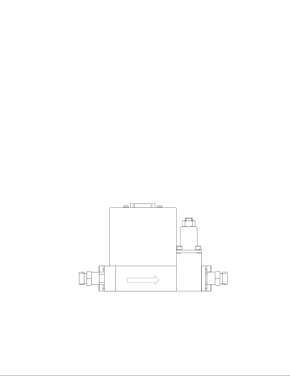
Figure 4: Side View of the 1500 Series Flow Controller........................................................ 28
Figure 5: Type 558 Dimensions............................................................................................. 37
Figure 6: Type 558 Mounting Holes ...................................................................................... 37
Tables
Table 1: Type D Connector Pinout...........................................................................................16
v

List of Figures and Tables
vi

Safety Procedures and Precautions
Safety Procedures and Precautions
The foll o wi n g g en era l s a fety p reca utions mu s t be observed during a l l p hases of op era ti o n o f this
instrument. Failure to comply wi th these precauti o n s o r wi th specific warnings els ewhere in
this manual violates safety standards of intended use of the instrument. MKS Instruments, Inc.
assumes no liability for the customer's failure to comply with these requirements.
Warning
DO NOT SUBSTITUTE PARTS OR MODIFY INSTRUMENT
Do not install substitute parts or perform any unauthorized modification to the instrument.
Return the instrument to an MKS Calibration and Service Center for service and repair to ensure
that all safety features are maintained.
Before performing mass flow controller valve adjustments,
you MUST purge your process equipment and the MFC with
an inert gas , such as argon or nitrogen, and isolate the MFC
from toxic and haza rdous gases. Use an inert surrogate gas
while adjusting the valve preload as a safeguard against
inadvertent exposure to any toxic or hazardous gas. A
release of hazardous or toxic gas could caus e serious injury.
If necessary, remove the MFC from the process equipment to
adjust the valve.
Questions concerning the safe handling of toxic or hazardous
gases may be answered by consulting your corporate policy,
a government agency such as OSHA or NIOSH, or experts
familiar with your process gas.
MKS assumes no liability for safe handling of toxic or
hazardous gases.
SERVICE BY Q UAL IFI E D PE RS O NNE L O NL Y
Operating personnel must not rem ove i ns t rument covers. Component replacement and i nt ernal
adjustments must be made by qualified service personnel only.
USE CAUTION WHE N O PE RAT I NG WIT H H AZ ARDOUS MATERIALS
If hazardous materials are used, us ers m u st t ake respons i bility to observe the proper safety
precaution s , co m p l et el y p u rg e t h e i n s t ru m ent when necessary, an d i n s u re t h at t h e m at eri al u s ed i s
compatible with sealing materials.
1

Safety Procedures and Precautions
PURGE THE INSTRUMENT
After installing the unit, or before its removal from a system, be sure to purge the unit completely
with a clean dry gas to eliminate all traces of the previously u s ed fl o w m aterial.
DO NOT OPERATE IN EXPLOSIVE ATMOSPHERES
To avoid explosion, do not operate this product in an explosive atmosphere unless it has been
specificall y cert i f i ed fo r s u ch op erat i o n .
USE PROPER FIT T ING S AND T I G H T E NING PRO CE DURE S
All instrument fittings must be consistent with instrument specifications, and compatible with the
intended use of the instrument. Assemble and tighten fittings according t o m an u fact u rer's
direction.
CHECK FOR LEAK-TIGHT FITTINGS
Before proceeding to instrument s et up, careful l y check al l pl um bi ng connecti ons to th e
instrument to insure leak-tight installation.
OPERATE AT SAFE INLET PRESSURES
This unit should never be operated at pressures higher than the rated maximum pressure (refer to
the product specifications for the maximum allowable pressure).
INSTALL A SUITABLE BURST DISC
When operating from a pressurized gas source, a suitable burst disc should be installed in the
vacuum system to prevent system explosion should the system pressure rise.
KEEP THE UNI T FRE E O F CO NT AMI NANT S
Do not allow contaminants of any kind to enter the unit before or during use. Contamination
such as dust, dirt, lint, glass chips, and metal chips may permanently damage the unit.
ALLOW THE UNIT TO WARM UP
If the unit is used to control dangerous gases, they should not be applied before the unit has
completely warmed up. A positive shutoff valve can be employed to ensure that no erroneous
flow can occur during warm up.
2
Safety Procedures and Precautions
Definitions of WARNING, CAUTION, and NOTE messages used throughout the manual.
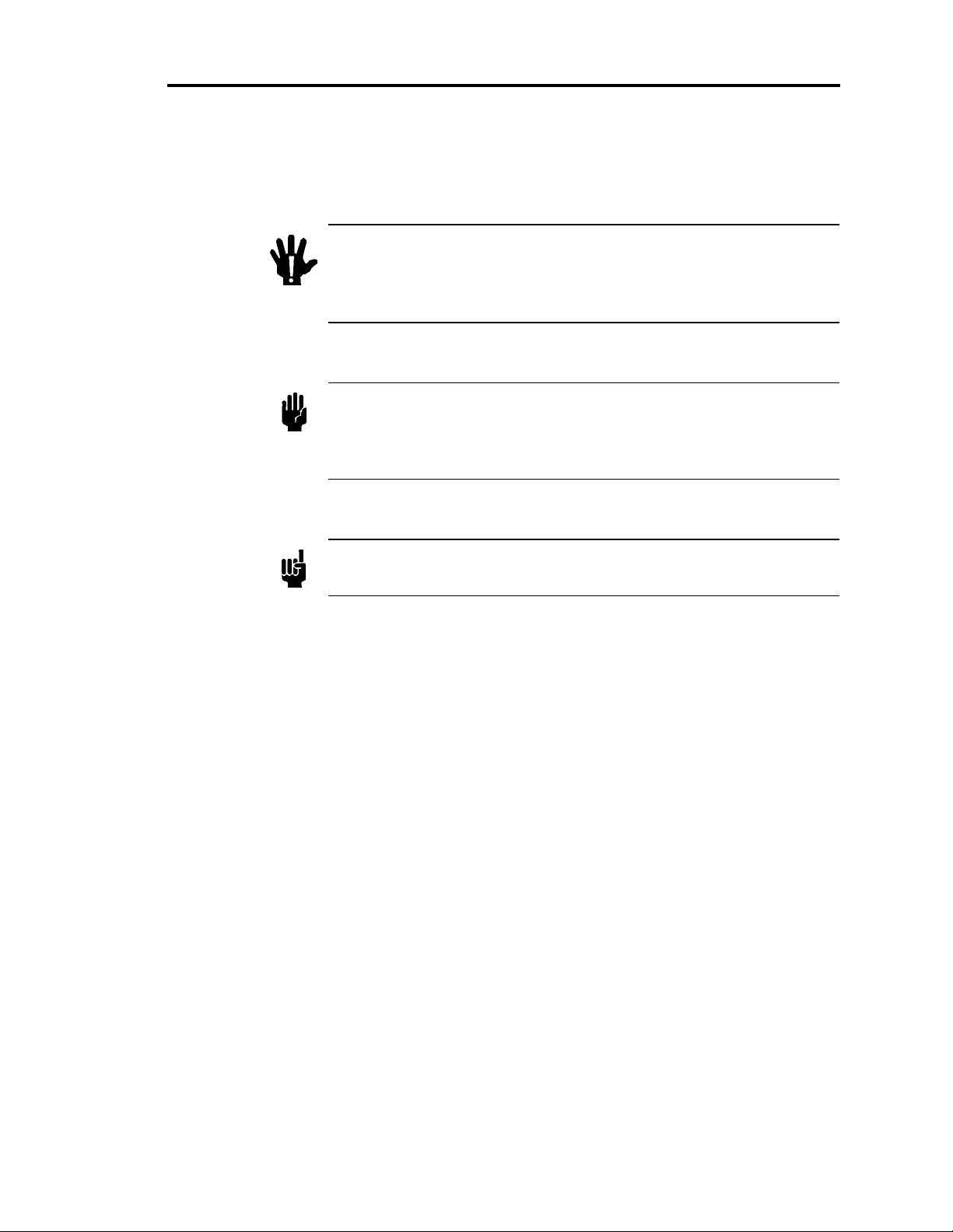
Warning
Caution
Note
The WARNING sign de notes a hazard. It calls attention to a
procedure, prac ti ce, condition, or the like, which, if not
correctly performe d or adhered to, could result in i nj ury to
personnel.
The CAUTION si gn denotes a hazard . I t call s atten ti on to an
operatin g p ro cedure, practi ce, or the lik e, which, if not correctly
performed or adhered to, could result in dama ge to o r d es truction of
all or part of the product.
The NOTE sign denotes important information. It calls attention to a
procedure, practice, condition, or the like, which is essential to highlight.
3

Safety Procedures and Precautions
This page intentionally left blank.
4

Chapter One: General Informa t ion Introduction
Chapter One: General Information
Introduction
The MKS Mass-Flo® Meter and Controller 1500 Series of i ns t rum ents accuratel y m eas ure and
control the mass flow rate of gases. Based on a patented flow sensing technique (U.S. Patent
Nos. 4464932, 4679585; Foreign Patents - Patents Pending), the flow controllers provide
continuous monitoring and cl osed-l oop cont rol of gas fl ows. B ecaus e it is
being measured, it is not necessary to correct for variations in gas temperature and pressure. The
instruments also utilize a patented
eliminate oscillation.
The MKS 1500 Series Flow Meter/Controllers are designed for general, industrial, and process
applications within a range of 20 to 200 slm (400 scfh). The flow meter/controllers offer
excellent RFI protection, digital open/close valve commands, and a safety shutoff feature for set
points under 0.2% of Full Scale. Accuracy is better than 1.0% of Full Scale in most ranges and
the settling time is less than 2 seconds (to within 2% of set point).
balanced forces
control valve to provide fast response and to
mass
flow that is
The 1500 Series includes the following types:
•
Type 1559A Mass Flow Controller (valve normally
•
Type 1562A Mass Flow Controller (valve normally
•
Type 558C Mass Flow Meter configured in Types 1559A and 1562A
closed
open
)
)
5

How This Manual is Organized Chapter One: General Informat i on
How This Manual is Organized
This manual is designed to provide instructions on how to set up and install 1500 Series Flow
Meter/Controller instrument.
Before installing your 1500 Series Flow Meter/Controller in a system and/or operating it,
carefully read and familiarize yourself with all precautionary n o tes i n the
and Procedures
WARNING
section at the front of this manual. In addition, ob serve and obey all
CAUTION
and
notes provided throughout the manual.
Safety Messages
Chapter One,
General Information
, (this chapter) introduces the product and describes the
organization of the manual.
Chapter Two,
Installation
, explains environmental requirements and practical considerations to
take into account when determining the location for the flow instrument. Once the mass flow
controll er i s p l aced i n an app ro p ri ate environmen t , refer to the mech an i cal d i m en s i o n s i n t h e
Set Up
section and follow the instructions for gas line connections.
Chapter Three g i v es an
Overview
of the 1500 Series Flow Meter/Controller instruments. It
describes the components of the instruments and lists the electrical pinouts of their Type “D”
connectors.
Chapter Four,
Operation
, explains how to start up and operate the flow meter/controller. Once
the instrument is in operation, review the next two sections to understand how the controller
adjusts flow rate to set point and to learn how to override the control valve.
Chapter Five,
Theory of Oper a t i o n
, describes in a general way how the Flow Meter/Controller
operates in a gas flow system. This chapter also provides information on how to use a Gas
Correction Factor when interpreting the output signal for a gas other than nitrogen.
Chapter Six,
Maintenance,
provides instructions on how to adjust the control valves in the
1559/1562 units.
Chapter Seven,
Troubleshooting,
contains a checklist for reference in the event that your unit
does not produce consistently good results.
Appendix A lists
Product Specifications
for the Flo w M et er/ C on t ro l l er i n struments.
Appendix B shows
Type 558 Meter Dimensions and Mounting Holes.
Appendix C provides
Gas Correction Factors
for the most commonly used gases.
6

Chapter One: General Informa t ion Customer Support
Customer Support
Standard maintenance services are available at all of our regional MKS Calibration and Service
Centers, l i s ted on the back cov er. In additi o n, MKS accepts t h e i n s t ru m en t s o f o t h er
manufacturers for recalibration using the Primary and Transfer Standard calibration equipment
located at all of our regional service centers. Should any difficulties arise in the use of your 1500
Series instrument, or to obtain information about companion products MKS offers, contact any
authorized MKS Calibration and Service Center. If it is necessary to return the instrument to
MKS, please obtain an ERA Number (Equipment Return Authorization Number) from the MKS
Calibration and Service Center before shipping. The ERA Number expedites handling and
assures proper servicing of your instrument.
Please refer to the inside of the back cover of this manual for a list of MKS Calibration and
Service Centers.
Warning
All returns to MKS Instruments must be free of harmful,
radioactive, corrosive, or toxic materials.
7

Customer Support Chapter One: General Informat i on
This page intentionally left blank.
8
 Loading...