

MKS Mass-Flo 1479A Instruction Manual

MKS Type 1479A
119474-P1
Rev B, 10/97
Instruction Manual
Mass-Flo
®
Controller
Six S hatt uck Road
Andover, MA 01810-2449
(800) 227-8766 or (978) 975-2350
Fax: (978) 975-0093
E-mai l: mk s@mksinst.com
Web site: http://www.mksinst.com

WARRANTY
Type 1479 A Eq ui pm e nt
MKS Instruments, Inc. (
the equipment described above (the “equipment”) manufactured by
free from defec ts in m at erials an d wo rk mans hip and w ill corr ec tly p erfo rm all d ate related operations, including without limitation accepting data entry, sequencing,
sorting, comparing, and reporting, regardless of the date the operation is performed
or the date inv olved in the operat ion, provided that, if the equi pment exchan ges
data or is otherwise used with equi pment, software, or other pro ducts of others,
such products o f others the mselves correc tly perform all date-rel ated operations
and store and transmit dates and date-related data in a format compatible with
MKS
equipment. THIS WARRANTY IS
DATE-RELATED OPERATIONS.
For the period commencing with the date of shipment of this equipment and ending
two year s later,
defective in materials or workmanship or with respect to the date-related operations
warranty without charge to the purchaser. The foregoing shall constitute the
exclusive and sole remedy of the purchaser for any breach by
warranty.
The purchaser, before returning any equipment covered by this warranty, which is
asserted to be defective by the purchaser, shall make specific written arrangements with respect to the responsibility for shipping the equipment and handling
any other inc ident al char ges with the
which the eq uipment w as purc hased or, in the case of a direc t p ur c hase fro m
MKS
with the
home office in Andover, Massachusetts, USA.
MKS
) warran t s th at for tw o y e ar s fr o m th e dat e of s h ipment
MKS
MKS’
SOLE WARRANTY CONCERNING
MKS
will, at its opt ion, either r epair or rep lace any p art which is
MKS
MKS
sal es repres ent ative or distr ibutor from
shall be
of this
MKS
,
This warr anty does not ap ply to any equip ment whic h has n ot been i nstalle d and
used in accorda nce with t he specif icatio ns reco mmende d by
and normal u se of the equipment.
for indirect, special, consequential, or incidental damages in connection with, or
arising out of, the sale, performance, or use of the equipment covered by this
warranty.
MKS
recommends that all
periodic ally (typ ically every 6 to 12 months) to e nsure accurate read ings. When a
product is retur ned to
preventative maintenance not covered by any warranty.
THIS WARRANTY IS IN LIEU OF ALL OTHER RELEVANT WARRANTIES,
EXPRESSED OR IMPLIED, INCLUDING THE IMPLIED WARRANTY OF
MERCHANTABILITY AND THE IMPLIED WARRANTY OF FITNESS FOR A
PARTICULAR PURPOSE, AND ANY WARRANTY AGAINST INFRINGEMENT OF
ANY PATENT.
MKS
11-98 119474-P1
MKS
shall not b e l iable und er any c ircumst ances
MKS
pressure and flow products be calibrated
for this p eriodic re-c alibrati on it is co nsidered nor mal
MKS
for the proper

MKS Type 1479A
119474-P1
Rev B, 10/97
Mass-Flo
®
Controller

Copyright © 1997 by MKS Instruments, Inc.
All rights reserved. No part of this work may be reproduced or transmitted in any form or by
any means, electronic or mechanical, including photocopying and recording, or by any
informa t i o n s t o r a g e or r et r ieval system, except as may be exp r es s l y per m itted in writing by MKS
Instruments, Inc.
Mass-Flo
Cajon
Teflon
Kalrez
Swagelok
Kel-F
DeviceNet
®
is a registered trademark of MKS Instruments, Inc., Andover, MA
®
, VCR®, and VCO® are registered trademarks of Cajon Company, Macedonia, OH
®
is a registered trademark of E. I. DuPont de Nemours and Co. Inc., Wilmington, DE
®
, and Viton® are registered trademarks of DuPont Dow Elastomers Wilmington, DE
®
and NUPRO® are registered trademarks of Crawford Fitting Company, Solon, OH
®
is a regist ered trademark of 3M, Minneapo l i s , MN
®
is a registered trademark of Open DeviceNet Vendor Association, Inc., Coral
Springs, FL
U.S. Patent 5,461,913; foreign patents pending

Table of Contents
Table of Contents
Mass Flow Controller Safety Information............................................................................... 1
Symbols Used in This Instruction Manual..................................................................1
Symbols Found on the Unit .......................................................................................2
Safety Pr oced u res an d Precautions ............................................................................. 3
Chapter One: General Information......................................................................................... 5
Introduction............................................................................................................... 5
Design Features............................................................................................. 5
Reliability..................................................................................................... 6
Cleanliness Features...................................................................................... 6
How This Manual is Organized.................................................................................. 7
Customer Support...................................................................................................... 8
Chapter Two: Installation......................................................................................................9
How To Unpack the Type 1479 Controller.................................................................9
Opening the Package..................................................................................... 9
Unpacking Checklist.................................................................................................. 10
Environmental Requirements..................................................................................... 10
Setup.........................................................................................................................11
Dimensions................................................................................................... 12
Gas Line Connections................................................................................................ 13
Standard Fittings........................................................................................... 13
Optional Fittings........................................................................................... 13
Mounting a Type 1479 MFC...................................................................................... 13
The Type 2479 MFC ................................................................................................. 15
Mounting a Type 2479 MFC......................................................................... 15
Interface Cables ......................................................................................................... 16
Generic Shielded Cable Description.............................................................. 17
Example 1: Preferred Method To Connect Cable.......................................... 18
Example 2: Alternate Method To Connect Cable.......................................... 18
Chapter Three: Overview.......................................................................................................19
iii

Table of Contents
Electrical Connections................................................................................................ 19
9-Pin Type “D” Connector.............................................................................19
15-Pin Type “D” Connector...........................................................................20
P.C. Edge Card Connector.............................................................................21
The Gas Correction Factor (GCF)............................................................................... 22
Control Valve.............................................................................................................23
Chapter Four: Operation........................................................................................................25
How To Start Up the Flow Controller.........................................................................25
How To Zero the Flow Controller.............................................................................. 26
How To Adjust the Controller Gain............................................................................27
How To Override the Valve........................................................................................28
Priority of the Commands..............................................................................28
The Optional Input.....................................................................................................29
Chapter Five: Theory of Operation.........................................................................................31
Flow Path................................................................................................................... 31
Measurement Technique.............................................................................................31
Control Circuitry........................................................................................................ 32
Chapter Six: Maintenance......................................................................................................33
General.......................................................................................................................33
Zero Adjustment ........................................................................................................33
Chapter Seven: Troubleshooting............................................................................................35
Troubleshooting......................................................................................................... 35
How To Adjust the Valve Preload..............................................................................37
Appendix A: Product Specifications.......................................................................................43
Performance Specifications ........................................................................................43
Environmental Specifications.....................................................................................44
Electrical Specifications.............................................................................................44
Physical Specifications...............................................................................................45
Appendix B: Gas Correction Factors......................................................................................47
Appendix C: MFC Sizing Guidelines.....................................................................................51
General Information...................................................................................................51
iv

Table of Contents
How To Determine the Flow Controller Range.......................................................... 52
How To Determine the Valve Configuration .............................................................. 53
Appendix D: Model Code......................................................................................................57
Model Code............................................................................................................... 57
Index...................................................................................................................................... 61
v

Table of Contents
vi

List of Figures and Tables
List of Figures and Tables
Figures
Figure 1: Outline Dimensions of the 1479 Flow Controller....................................................12
Figure 2: Side View of the 1479 Flow Controller.................................................................. 13
Figure 3: Mounting Dimensions of the 1479 Flow Controller................................................ 14
Figure 4: Outline Dimensions of the Type 2479 Unit.............................................................15
Figure 5: Mounting Dimensions of the Type 2479 Flow Controller....................................... 15
Figure 6: Preferred Method....................................................................................................18
Figure 7: Alternate Method To Use When Cable Clamp is Not Available .............................. 18
Figure 8: Location of the Retaining Screws........................................................................... 38
Figure 9: Location of the Jam Nut and Adjustment Nut......................................................... 39
Figure 10: The PC Board....................................................................................................... 41
Tables
Table 1: Definition of Symbols Found on the Unit.....................................................................2
Table 2: MK S In t erface Cables.................................................................................................16
Table 3: 9-Pin Type “D” Connector Pinout...............................................................................19
Table 4: 15-Pin Type “D” Connector Pinout.............................................................................20
Table 5: 20-Pin Edge Card Connector Pinout ...........................................................................21
Table 6: Troubleshooting Chart................................................................................................ 35
Table 7: Maximum Valve Current............................................................................................40
Table 8: Required Valve Current Headroom.............................................................................42
Table 9: Cv Pressure Factors....................................................................................................53
Table 10: Valve Configuration Selection Guide........................................................................54
vii

List of Figures and Tables
viii

Mass Flow Controller Safety Information
Mass Flow Controller Safety Information
Symbols Used in This Instruction Manual
Definitions of WARNING, CAUTION, and NOTE messages used throughout the manual.
Warning
Caution
Note
The WARNING sign denote s a hazard to personnel. It call s
attention to a procedure, practice , condition, or the like,
which, if not correctly performed or adhered to, c ould result
in injury to personnel .
The CAUTION s i gn denotes a hazard to eq uipment. I t call s
attention to an operatin g p ro ced ure, practice, or the lik e, which, i f
not correctly performed or adhered to, cou l d result in damage to or
destruction of all or part of the product.
The NOTE sign denotes important information. It calls attention to a
procedure, practice, condition, or the like, which is essential to highlight.
1
Mass Flow Controller Safety Information
g
g
g
g
g
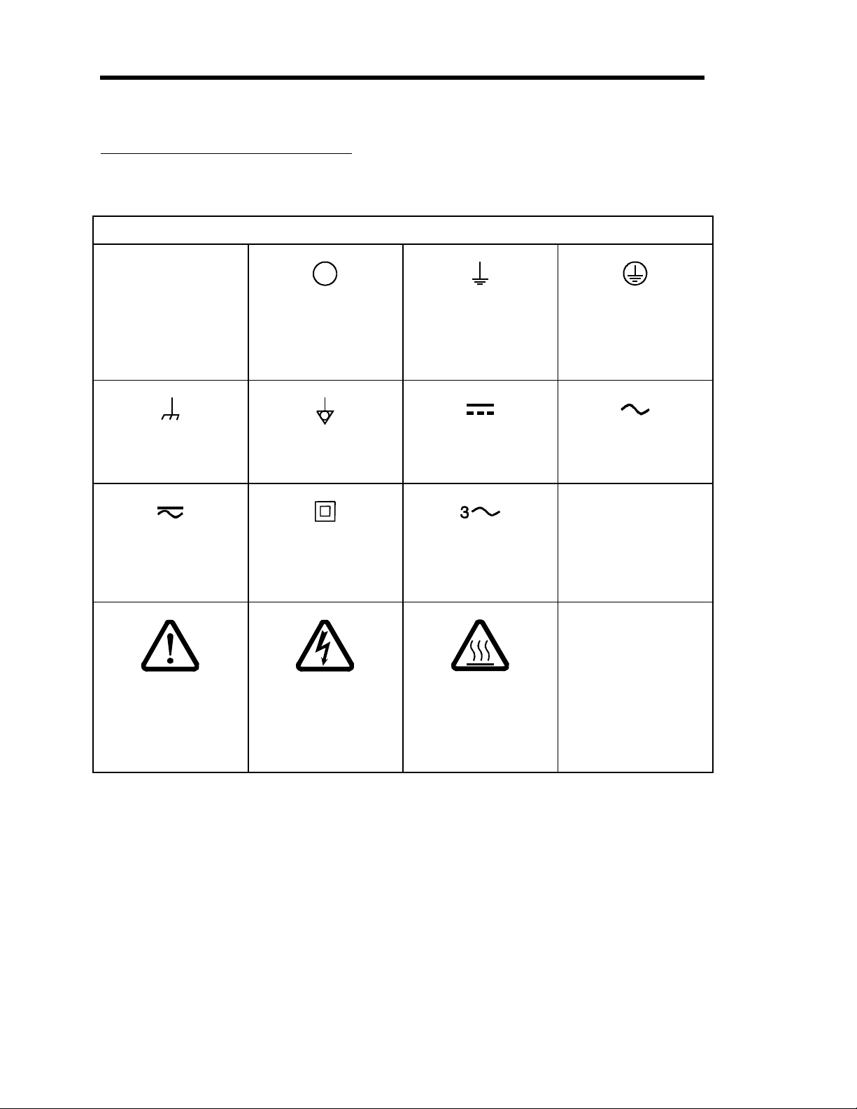
Symbols Found on the Unit
The following table describes symbols that may be found on the unit.
Definition of Symbols Found on the Unit
|
On (Supply)
IEC 417, No.5007
Off (Supply)
IEC 417, No.5008
Earth (
IEC 417, No.5017
round)
Protective earth
round)
(
IEC 417, No.5019
Frame or chassis
IEC 417, No.5020
Both direct and
alternatin
IEC 417, No.5033-a
Caution, refer to
accompanyin
ISO 3864, No.B.3.1
current
documents
Equipotentiality
IEC 417, No.5021
Class ll equipment
IEC 417, No.5172-a
Caution, risk of
electric shock
ISO 3864, No.B.3.6
Direct current
IEC 417, No.5031
Three phase
alternating current
IEC 617-2 No.020206
Caution, hot surface
IEC 417, No.5041
Table 1: Definition of Symbols Found on the Unit
Alternatin
IEC 417, No.5032
current
2

Mass Flow Controller Safety Information
Safety Procedures and Precautions
The foll o wi n g g en era l s a fety p reca utions mu s t be observed during a l l p hases of op era ti o n o f this
instrument. Failure to comply wi th these precauti o n s o r wi th specific warnings els ewhere in
this manual violates safety standards of intended use of the instrument and may impair the
protection provided by the equipment. MKS Instruments, Inc. assumes no liability for the
customer’s fai l ure to comply wi th these requirements.
DO NOT SUBSTITUTE PARTS OR MODIFY INSTRUMENT
Do not install substitute parts or perform any unauthorized modification to the instrument.
Return the instrument to an MKS Calibration and Service Center for service and repair to ensure
that all safety features are maintained.
SERVICE BY Q UAL IFI E D PE RS O NNE L O NL Y
Operating personnel must not at t empt com ponent replacem ent and i nt ernal adj us tm ent s. Any
service must be made by qualified service personnel only.
USE CAUTION WHE N O PE RAT I NG WIT H H AZ ARDOUS MATERIALS
If hazardous materials are used, obs erve t he proper s afety precauti ons , com p let ely purge t he
instrument when necessary, and ensure that the material used is compatible with the wetted
materials in this product, including any sealing materials.
PURGE THE INSTRUMENT
After installing the unit, or before removing it from a system, purge the unit completely with a
clean, dry gas to eliminate all traces of the previous ly used flow material.
USE PROPER PROCEDURE S WHEN PURGING
This instrument must be purged under a ventilation hood, and gloves must be worn for
protection.
DO NOT OPERAT E I N AN E XPL O S IVE ENVIRONMENT
To avoid explosion, do not operate this product in an explosive environment unless it has been
specificall y cert i f i ed fo r s u ch op erat i o n .
USE PROPER FIT T ING S AND T I G H T E NING PRO CE DURE S
All instrument fittings must be consistent with instrument specifications, and compatible with the
intended use of the instrument. Assemble and tighten fittings according to m anu fact u rer's
directions.
3

Mass Flow Controller Safety Information
CHECK FOR LEAK-TIGHT FITTINGS
Carefully check all vacuum component connections to ensure leak-tight installation.
OPERATE AT SAFE INLET PRESSURES
Never operate at pressures higher than the rated maximum pressure (refer to the product
specifications for the maximum allowable pressure).
INSTALL A SUITABLE BURST DISC
When operating from a pressurized gas source, install a suitable burst disc in the vacuum system
to prevent system explosion should the system pressure rise.
KEEP THE UNI T FRE E O F CO NT AMI NANT S
Do not allow contaminants to enter the unit before or during use. Contamination such as dust,
dirt, lint, glass chips, and metal chips may permanently damage the unit or contaminate the
process.
ALLOW THE UNIT TO WARM UP
If the unit is used to control dangerous gases, they should not be applied before the unit has
completely warmed up. Use a positive shutoff valve to ensure that no erroneous flow can occur
during warm up.
4

Chapter One: General Informa t ion Introduction
Chapter One: General Information
Introduction
The MKS Type 1479A Mass-Flo® controll er (MFC) is a met al s eal ed un i t wh i ch accu rat el y
measures and controls the mass flow rates of gases. The Type 2479A MFC adds a pneumatically
operated positive shutoff valve downstream. Based upon a patented MKS measurement
technique, the instrument is a laminar flow device whose precise indication of mass flow is
achieved through the use of a bypass element in parallel with a sensor tube. The 1479 controller
has a three-inch footprint and features the ability to accept TTL level commands to rem o t el y
open and close the control valve. The controller includes a metal cover and RF bypass
capacitors, and incorporates a design that virtually eliminates RFI and EMI interference. The
1479 MFC carries a CE Mark indicating compliance with the EMC Directive 89/336/89.
Use the 1479 MFC when both gas flow control and measurement are required. The controller is
available with the flow control valve in a normally closed configuration.
The 1479 mass flow controller (MF C ) can i nt erface to comp l ementary M KS equi pm ent (Types
147/647, 160, 246, 247) to display the reading and to provide the power, and set point
commands. (Additionally, the 167 unit can be used as a readout and set point generator, but it
does not supply power; the 660 unit can be used as a power supply and readout, though it cannot
send a set point to the flow controller.) Refer to the corresponding manuals for requirements and
instructions.
The 1479 flow controller is available in a variety of types and configurations to suit specific
needs. The options that must be specified when you order the flow controller include:
Connector:
•
Range:
•
Fittings:
•
Design Features
The design of the 1479 flow controller incorporates an advanced flow sensor, a new control
valve, and an optimized bypass. (U.S. and Foreign Patents; Patents Pending on the sensor.) The
latest gen erat i o n t w o- el em en t s en s i n g ci rcu i t p ro v i d es accurate, repeatabl e perfo rm an ce ev en i n
low flow ranges (< 1 0 sccm). A low temp erat u re effect fro m am b i en t t em p erat u re ch ang e an d a
low attitude sensitivity effect are also ensured. The newly optimized sensor/bypass arrangement
minimizes the flow splitting error for gases with different densities, which dramatically improves
measurement accuracy when gases other t h an t he cal i b rati on gas are us ed. The s u rface mount
electronics feature optional pin-to-pin compatibility with other manufacturer’s flow contro l l ers .
In addition, the variable valve control electronics provides for fast response to any set point.
Type “D” connector or recessed P.C. Edge Card connector
10, 20, 50, 100, 200, 500, 1000, 2000, 5000, 10, 000, 20, 000* sccm (N
equivalent) * Consult
®
Cajon
¼ inch di am et er t u b e wel d s t u b .
4-VCR® male compatible, ¼ inch Sw ag el o k® compatible, and
the factory for 20,000 sccm applications
2
5

Introduction Chapter One: General Informat i on
Reliability
To help provide excellent reliability, the design contains a low mechanical and electronic
components count and has successfull y pas sed t he fol lo wing t est s:
•
STRIFE, including temperature cycling and vibration (sine and random tests)
and with an overall metal braided, shielded cable, properly grounded at both ends:
•
EMC Directive 89/336/EEC for CE Mark compliance
Cleanliness Features
The 1479 controller uses metal for all external seals, thus eliminating elastomeric seals which are
a key source of particle generation, outgassing, and permeation. The metal seal also ensures
extremely l o w ex t ern al l eak ag e. The internal v al v e con t ro l p l u g i s T efl on
®
or Kel-F
®
(depending on flow range) or Kel-F (depending on flow range) which further reduces outgassing
and particle generation. The 1479A mechanical design minimizes wetted surface area and virtual
leaks, assuri ng rapi d drydown. To furt her enhance cl eanl i nes s , al l i nt ernal su rfaces are precis i on
machined, electropolished, and subjected to a proprietary cleaning process under Class 100
conditions. The instrument is assembled and double-bagged in a Class 100 environment.
6

Chapter One: General Information How This Manual is Organized
How This Manual is Organized
This manual is designed to provide instructions on how to set up and install a Type 1479 unit.
Before installing your Type 1479 unit in a system and/or operating it, carefully read and
familiarize yourself with all precautionary notes in the
section at the front of this manual. In addition, observe and obey all
CAUTION
notes provided throughout the manual.
Safety Messages and Procedures
WARNING
and
Chapter One: General Information,
(this chapter) introduces the product and describes the
organization of the manual.
Chapter Two: Installation,
explains environmental requirements and practical considerations to
take into account when selecting the proper setting for the mass flow controller.
Chapter Three: Overview,
describes, in a general way, how the flow controller operates in a gas
flow system. This chapter also provides information on how to use a Gas Correction Factor
when interpreting the output signal for a gas other than the calibration gas.
Chapter Four: Operation
, explains how to start up and operate the mass flow controller. It also
discusses how to override the control valve.
Chapter Five: Theory of Operation,
provides additional information on how the flow controller
operates.
Chapter Six: Maintenance,
lists a few general practices to follow to ensure that the flow
controller will perform optimally.
Chapter Seven: Troubleshoot i ng,
includes a table of hints for reference in the event that your
flow controller malfunctions.
Appendix A: Product Specifications,
Appendix B: Gas Correction Factors,
lists the specifications of the instrument.
provides a table listing the gas correction factors for the
most commonly used gases.
Appendix C: MFC Sizing Guidelines,
is provided for reference and describes how to calculate
the correct size MFC for an application. This information is useful if you need to purchase
another MFC or if you plan to use your MFC in another, different application.
Appendix D: Model Code,
provides product code information for the 1479 unit.
7

Customer Support Chapter One: General Informat i on
Customer Support
Standard maintenance and repair services are available at all of our regional MKS Calibration
and Service C en t ers , listed on t h e b ack cov er. In additi o n, MKS accepts t h e i n s t ru m en t s o f o t h er
manufacturers for recalibration using the Primary and Transfer Standard calibration equipment
located at all of our regional service centers. Should any difficulties arise in the use of your Type
1479 instrument, or to obtain information about companion products MKS offers, contact any
authorized MKS Calibration and Service Center. If it is necessary to return the instrument to
MKS, please obtain an ERA Number (Equipment Return Authorization Number) from the MKS
Calibration and Service Center before shipping. The ERA Number expedites handling and
ensures proper servicing of your instrument.
Please refer to the inside of the back cover of this manual for a list of MKS Calibration and
Service Centers.
Warning
All returns to MKS Instruments must be free of harmful,
corrosive, radioactive, or toxic materials.
8

Chapter Two: Installation How To Unpack the Type 1479 Controlle
r
Chapter Two: Installation
How To Unpack the Type 1479 Controller
MKS has carefully packed the 1479 flow controller so that it will reach you in perfect operating
order. Upon receiving the unit , however, you s houl d check for defect s, cracks , broken
connectors, etc., to be certain that damage has not occurred during shipment.
Note
If you find any damage, notify your carrier and MKS immediately. If it is necessary to return the
unit to MKS, obtain an ERA Number (Equipment Return Authorization Number) from the MKS
Service Center before shipping. Please refer to the inside of the back cover of this manual for a
list of MKS Calibration and Service Centers.
Opening the Package
The 1479 controller is assembled, leak tested with helium, and calibrated in a clean room
environment. The instrument is double-bagged in this environment to ensure maintenance of its
particle free cond i t ion during s h i p m en t . It is very i m p ortant to remov e t h e b ags acco rd i n g t o
clean room practices. To maintain at least a minimal level of clean room standards, follow the
instructions below.
1. Remove the outer bag in an ante room (garmenting room) or transfer box.
Do not allow this outer bag to enter the clean room.
2. Remove the inner bag in the clean room.
not
Do
inspection and are sure the unit arrived safely.
discard any packing materials until you have completed your
9

Unpacking Checklist Chapter Two: Installation
Unpacking Checklist
Standard Parts:
•
The 1479 flow controller
Option a l Acces s o ri es :
•
Electrical Connector Accessories Kit, 1479A-K1 (includes a mating connector for the I/O
connector)
•
Power Supply/Readout device
•
Cabling to connect the flow controller to the readout device
Environmental Requirements
Follow the guidelines listed below when installing and using the 1479 flow controller.
1. Maintain the normal operating temperature between 0° and 50° C (32° and 122° F).
2. Observe the pressure limits:
A. Maximum gas inlet pressure is 250 psig.
B. Operational differential pressure is:
10 to 40 psid for ≤ 5000 sccm units
15 to 40 psid for 10,000 and 20,000 sccm units
The standard valve configuration provides control over this range with the outlet at
atmospheric pressure.
3. Provide power input at ±15 VDC (±5%) @ 200 mA.
A. Maximum voltage/current at startup is ±15 VDC (±5%) @ 200 mA.
B. Typical steady state voltage/current should be ±15 VDC (±5%) @ 100 mA.
4. Allow 2 minutes for warm-up time.
5. Use high purity gas and filters in line upstream of the MFC.
6. Leave the power to the instrument on at all times, for optimal performance.
For addit i o nal i n fo rm at i o n refer t o
Appendix A: Product Specifications,
10
page 43.

Chapter Two: Installation Setu
p
Setup
Follow the guidelines below when setting up the 1479 flow controller.
1. Set the controller into position where it will be connected to a gas supply.
Placement of flow component s in an ori entat ion ot her t han t h at i n which t hey were
calibrated (t y p i cal l y h o ri zo n t al ) m ay cau s e a s m al l zero s h i ft . The zero offset can b e
removed accordi n g t o t he instructi o ns i n
2. Install the flow controller in the gas stream such that the flow will be in the direction of
the arrow on the side of the controller.
3. Allow ad equ at e cl earan ce fo r t h e cab l e co nn ect o r an d t u bing.
Straight Shielded connectors require approximately 3” (76.2 mm) height. Right Angle
connectors require approximately 2” (50.8 mm) height.
4. Posi t ion the flow co n t ro l l er t o p ro vide access to th e zero p o t entiometer.
How To Zero the Flow Controller,
page 26.
The zero potentiometer is located on the inlet side of the flow controller body.
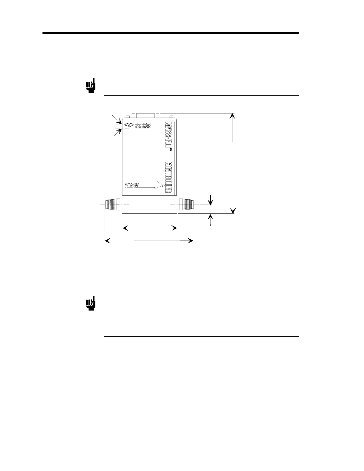
Refer to Figures 1, and 2, page 13, for outline dimensions, and Figure 3, page 14, for mounting
dimensions of the flow controller.
11
Setup Chapter Two: Installation
g
g
Dimensions
Note
Controller Ga in
Zero Adjust
All dimensions are listed in inches with millimeters referenced in
parentheses.
5.49 (139.5) with
Type "D" connector
or
5.30 (134.6) with recessed
P.C. Ed
3.00 (76.2)
Cajon 4-VCR or compatible 4.8 8 ( 123.9) shown
1/4" Swa
1/4" We ld S tub 4.34 (110.2)
elok or co mpatible 4. 44 (112.8)
e Board connector
0.50 (12.7)
Note
Figure 1: Outline Dimensions of the 1479 Flow Controller
The method used to measure the overall length of the unit varies with the
type of fitting. For VCR compatible fittings, the unit is measured from
mating face t o m at ing face. Fo r S w agelok compati b l e fittings, the unit is
measured from fitting end to fitting end (less nut). Weld stubs are
measured from end to end.
12
 Loading...