

MKS P250A, IM250A Instruction Manual

Type P250A / IM250A High Flow
2 Tech Drive
1041806-001 Rev C
10/13
Rate
Mass Flow Controller
Instruction Manual
Suite 201
Andover, MA 01810
978.645.5500
978.557.5100 FAX
www.mksinst.com

WARRANTY
Type P250A / IM250A Mass Flow Controller
MKS Instruments, Inc. (MKS) warrants that for one (1) year from the date of
shipment the equipment described above (the “equipment”) m anufactured by MKS
shall be free from defects in materials and workmanship.
For the period commencing with the date of shipment of this equipment and ending
one (1) year later, MKS will, at its option, either repair or replace any part which is
defective in materials or workmanship or with respect to the date-related operations
warranty without charge to the purchaser. The foregoing shall constitute the
exclusive and sole remedy of the purchaser for any breach by MKS of this
warranty.
The purchaser, before returning any equipment covered by this warranty, which is
asserted to be defective by the purchaser, shall make specific written arrangements with respect to the responsibility for shipping the equipment and handling
any other incidental charges with the MKS sales representative or distributor from
which the equipment was purchased or, in the case of a direct purchase from MKS,
with the MKS home office in Andover, Massachusetts, USA.
This warranty does not apply to any equipment which has not been installed and
used in accordance with the specifications recommended by MKS for the proper
and normal use of the equipment. MKS shall not be liable under any circumstances
for indirect, special, consequential, or incidental damages in connection with, or
arising out of, the sale, performance, or use of the equipment covered by this
warranty.
MKS recommends that all MKS pressure and flow products be calibrated
periodically (typically every 6 to 12 months) to ensure accurate readings. When a
product is returned to MKS for this periodic re-calibration it is considered normal
preventative maintenance not covered by any warranty.
THIS WARRANTY IS IN LIEU OF ALL OTHER RELEVANT WARRANTIES,
EXPRESSED OR IMPLIED, INCLUDING THE IMPLIED WARRANTY OF
MERCHANTABILITY AND THE IMPLIED WARRANTY OF FITNESS FOR A
PARTICULAR PURPOSE, AND ANY WARRANTY AGAINST INFRINGEMENT OF
ANY PATENT.

1041806-001 Rev C
10/13
Type P250A / IM250A High Flow Rate
2 Tech Drive
Suite 201
Andover, MA 01810
978.645.5500
978.557.5100 FAX
www.mksinst.com
Mass Flow Controller

Copyright © 2013 by MKS Instruments, Inc.
All rights reserved. No part of this work may be reproduced or transmitted in any form or by any means,
electronic or mechanical, including photocopying and recording, or by any information storage or retrieval
system, except as may be expressly permitted in writing by MKS Instruments, Inc.
Printed in the United States of America
DeviceNet™ is a trademark of Open DeviceNet Vendor Association, Inc., Coral Springs, FL
Swagelok and VCR are registered trademarks of Swagelok Marketing Company, Solon, OH
ii

Table of Contents
Table of Contents
Mass Flow Device Safety Information ............................................................................................................. 1
Symbols Used in This Instruction Manual .................................................................................................................... 1
Symbols Found on the Unit ........................................................................................................................................... 1
Safety Procedures and Precautions ................................................................................................................................ 2
Sicherheitshinweise für das Massenflussgerät................................................................................................. 3
In dieser Betriebsanleitung vorkommende Symbole ..................................................................................................... 3
Erklärung der am Gerät angebrachten Symbole ............................................................................................................ 3
Sicherheitsvorschriften und Vorsichtsmaßnahmen ....................................................................................................... 4
Informations de sécurité pour appareils de mesure/contrôle de débit massique ......................................... 5
Symboles utilisés dans ce manuel d'utilisation .............................................................................................................. 5
Symboles figurant sur l'unité ......................................................................................................................................... 5
Mesures de sécurité et précautions ................................................................................................................................ 6
Medidas de seguridad del dispositivo de flujo de masa .................................................................................. 7
Símbolos usados en este manual de instrucciones ......................................................................................................... 7
Símbolos hallados en la unidad ..................................................................................................................................... 7
Procedimientos y precauciones de seguridad ................................................................................................................ 8
マスフロー機器の安全に関する情報 ...................................................................................................................... 9
本取扱説明書のマーク ................................................................................................................................................... 9
本機器のマーク ............................................................................................................................................................... 9
安全対策について .......................................................................................................................................................... 9
질량 유량 장치 안전 정보 ................................................................................................................................ 13
본 지침 매뉴얼에 사용되는 기호들 ......................................................................................................................... 13
장치에 표시된 기호들 ............................................................................................................................................... 13
안전 절차 및 예방조치 .............................................................................................................................................. 13
. .................................................................................................................................................................................... 15
How This Manual is Organized ...................................................................................................................... 17
Chapter One: General Information .............................................................................................................. 18
Introduction ................................................................................................................................................................. 18
How the MFC Works .................................................................................................................................................. 18
Operation of the MFC with Gases other than Nitrogen ............................................................................................... 19
Chapter Two: Installation .............................................................................................................................. 22
Unpacking the P250A Mass Flow Controller .............................................................................................................. 22
Verifying Use Requirements Prior to Installation ....................................................................................................... 22
Understanding Dimensional Constraints ..................................................................................................................... 23
Performing MFC Installation....................................................................................................................................... 28
iii

Table of Contents
Chapter Three: Operation ............................................................................................................................. 30
Analog 9-pin / 15-pin Interface Operation .................................................................................................................. 30
4-20 mA IO 15-pin Interface Operation ...................................................................................................................... 34
DeviceNet Interface Operation .................................................................................................................................... 36
RS485 Interface Operation .......................................................................................................................................... 40
Profibus Interface Operation ........................................................................................................................................ 42
General Operational Functions .................................................................................................................................... 45
Chapter Four: Maintenance and Troubleshooting ..................................................................................... 50
General Information .................................................................................................................................................... 50
Zeroing the MKS P250A High Flow Rate Mass Flow Controller ............................................................................... 50
Customer Support ........................................................................................................................................................ 55
Repair .......................................................................................................................................................................... 55
Troubleshooting ........................................................................................................................................................... 56
Chapter Five: Diagnostic Interface Setup, Configuration, and Operation ............................................... 62
Step 1: Install the Java™ Plug-In ................................................................................................................................ 62
Step 2: Configure TCP/IP Settings for Communication to P250A .............................................................................. 63
Step 3: Connect to the P250A High Flow Rate Mass Flow Controller ....................................................................... 65
Monitor Mode ................................................................................................ .............................................................. 66
Setup Mode .................................................................................................................................................................. 71
Appendix A: Product Specifications ............................................................................................................. 80
Performance Specifications ......................................................................................................................................... 80
Physical Specifications ................................................................ ................................................................................ 80
Environmental Specifications ...................................................................................................................................... 81
Electrical Specifications .............................................................................................................................................. 81
Appendix B: Model Code Explanation ......................................................................................................... 84
Model Code Description .............................................................................................................................................. 84
Appendix C: Health and Safety Form .......................................................................................................... 88
iv

List of Figures
List of Figures
Figure 1: Front View of the P250A MFC ......................................................................................................... 24
Figure 2: Bottom View of the P250A MFC ...................................................................................................... 24
Figure 3: End View of the P250A MFC ........................................................................................................... 25
Figure 4: Top View of the P250A MFC (DeviceNet Interface) ....................................................................... 25
Figure 5: Front View of the IM250A MFC ...................................................................................................... 26
Figure 6: Bottom View of the IM250A MFC ................................................................................................... 26
Figure 7: End View of the IM250A MFC ......................................................................................................... 27
Figure 8: Top View of the IM250A MFC (Analog Interface) .......................................................................... 27
Figure 9: Serial Number Label.......................................................................................................................... 28
Figure 10: DeviceNet Connector Pin Diagram ................................................................................................. 36
Figure 11: Devicenet Baud Rate Switch ........................................................................................................... 38
Figure 12: Devicenet MAC ID Switches .......................................................................................................... 38
Figure 13: RS485 Baud Rate Switch ................................................................................................................ 41
Figure 14: RS485 MACID Switches ................................................................................................................ 41
Figure 15: Profibus (female DSUB) Connector Pin Diagram .......................................................................... 42
Figure 16: Profibus (male DSUB) Power Connector Pin Diagram. ................................................................. 43
Figure 17: Effects of the Proportional Term (Low Proportional Term) ........................................................... 45
Figure 18: Effects of the Proportional Term (High Proportional Term) ........................................................... 46
Figure 19: Effects of the Integral Term (Low Integral Term) .......................................................................... 46
Figure 20: Effects of the Integral Term (High Integral Term) .......................................................................... 46
Figure 21: Java Download Window .................................................................................................................. 63
Figure 22: Java License Agreement .................................................................................................................. 63
Figure 23: Java Installation Window ................................................................................................................ 63
Figure 24: Windows XP Shell Command Prompt ............................................................................................ 64
Figure 25: Windows XP Shell Command Window .......................................................................................... 64
Figure 26: Windows XP Shell Command Window (HostIP) ........................................................................... 65
Figure 27: P250A Embedded Interface (Monitor Mode / Device Page) ........................................................... 66
Figure 28: P250A Embedded Interface (Monitor Mode / Plot Page) ............................................................... 68
Figure 29: P250A Embedded Interface (Monitor Mode / Diagnostics Page) ................................................... 69
Figure 30: P250A Embedded Interface (Monitor Mode / Configuration Page) ............................................... 70
Figure 31: P250A Embedded Interface (Setup Mode / Configuration Page) ................................................... 71
Figure 32: P250A Embedded Interface (Setup Mode / Device Page) ............................................................... 72
Figure 33: P250A Embedded Interface (Setup Mode / Device Page) Creating A New Gas Instance .............. 73
Figure 34: P250A Embedded Interface (Setup Mode / Device Page) Changing Full Scale Flow Range ......... 73
Figure 35: P250A Embedded Interface (Setup Mode / Plot Page) ................................................................... 74
Figure 36: P250A Embedded Interface (Setup Mode / Configuration Page) ................................................... 75
Figure 37: P250A Embedded Interface (Setup Mode / Optional PC Page) ...................................................... 77
Figure 38: P250A Embedded Interface (Setup Mode / Plot Page) Enabled Optional Input ............................. 79
v

List of Tables
List of Tables
Table 1: Definition of Symbols Found on the Unit ............................................................................................ 1
Tabelle 2: Bedeutung der am Gerät angebrachten Symbole .............................................................................. 3
Tableau 3: Définition des symboles sur l'unité ................................................................................................... 5
Tabla 4: Definición de los símbolos hallados en la unidad ................................................................................ 7
表 5: 本機器に使用されているマークについて ...................................................................................................... 9
표 6: 장치에 표시된 기호들의 정의 .............................................................................................................. 13
Table 7: MKS Interface Cables ................................................................ ........................................................ 30
Table 8: Analog I/O 9-pin DSUB Pinouts (Model Code A) ............................................................................ 31
Table 9: Analog I/O 15-pin DSUB Pinouts (Model Code B) ........................................................................... 32
Table 10: 4-20 mA I/O 15-pin DSUB Pinouts (Model Code G) ...................................................................... 34
Table 11: DeviceNet Connector Pinouts (Model Code 6) ................................................................................ 36
Table 12: DeviceNet Network Status LED Indicators ..................................................................................... 37
Table 13: RS485 Connector Pinouts (Model Code 5) ...................................................................................... 40
Table 14: RS485 Module Status LED Indicators ............................................................................................. 40
Table 15: Profibus Communications Connector Pinout ................................................................................... 42
Table 16: Profibus Power Connector Pinout .................................................................................................... 43
Table 17: MFC Troubleshooting Chart ............................................................................................................ 56
vi

Mass Flow Device Safety Information
List of References
The documents listed below are referenced throughout this manual.
[1] “DeviceNet Specification, Volume I: DeviceNet Communication Model and Protocol”, Open DeviceNet
Vendors Association, Inc. Release 2.0.
[2] “DeviceNet Specification, Volume II: DeviceNet Profiles and Object Library”, Open DeviceNet
Vendors Association, Inc. Release 2.0.
[3] “Sensor/Actuator Network Common Device Model”, SEMI Standards Document E54.1-0097.
[4] “Sensor/Actuator Network Communications Standard for DeviceNet”, SEMI Standards Draft Document
E54.4-0097.
[5] “Sensor/Actuator Network Specific Device Model for Mass Flow Devices”, SEMI Standards Draft
Document #2253C.
[6] “Sensor/Actuator Network Standard”, SEMI Standards Document E54-0097.
[7] SEMI E17-00-0060 Guideline for Mass Flow Controller Transient Characteristics Tests
[8] SEMI E18-00-0091 Guideline for Temperature Specifications of the Mass Flow Controller
[9] SEMI E27-00-0092 Standard for Mass Flow Controller and Mass Flow Meter Linearity
[10] SEMI E28-00-0092 Guideline for Pressure Specifications of the Mass Flow Controller
[11] SEMI E52-00-0611 Practice for Referencing Gases and Gas Mixtures Used in Digital Mass Flow
Controllers
[12] SEMI E56-00-1296 Test Method for Determining Accuracy, Linearity, Repeatability, Short Term
Reproducibility, Hysteresis, and Dead Band of Thermal Mass Flow Controllers
[13] SEMI E80-00-0299 Test Method Determining Attitude Sensitivity of Mass Flow Controllers
vii

Mass Flow Device Safety Information
This page intentionally left blank.
viii
Mass Flow Device Safety Information
Warning
The WARNING sign denotes a hazard. It calls attention to a procedure, practice,
condition, or the like, which, if not correctly performed or adhered to, could result
in injury to personnel.
Caution
The CAUTION sign denotes a hazard. It calls attention to an operating procedure,
practice, or the like, which, if not correctly performed or adhered to, could result in
damage to or destruction of all or part of the product.
Note
The NOTE sign denotes important information. It calls attention to a procedure, practice,
condition, or the like, which is essential to highlight.
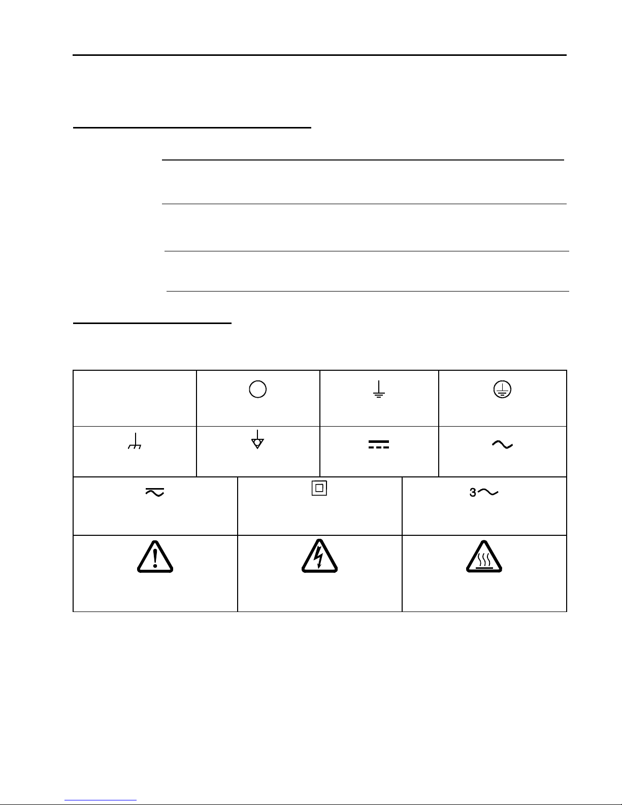
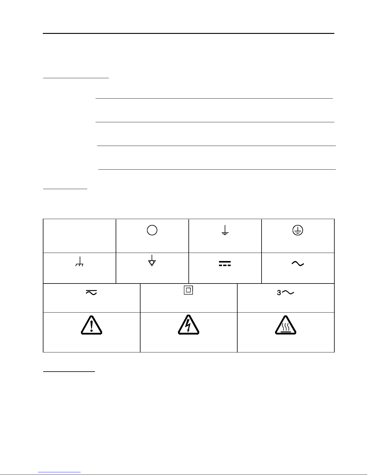
|
On (Supply)
IEC 417, No. 5007
Off (Supply)
IEC 417, No. 5008
Earth (ground)
IEC 417, No. 5017
Protective Earth (ground)
IEC 417, No. 5019
Frame or Chassis
IEC 417, No. 5020
Equipotentiality
IEC 417, No. 5021
Direct Current
IEC 417, No. 5031
Alternating Current
IEC 417, No. 5032
Both Direct and Alternating Current
IEC 417, No. 5033-a
Class II Equipment
IEC 417, No. 5172-a
Three Phase
Alternating Current
IEC 617-2, No. 020206
Caution (refer to accompanying
documents)
ISO 3864, No. B.3.1
Caution, Risk of Electric Shock
ISO 3864, No. B.3.6
Caution, Hot Surface
IEC 417, No. 5041
Mass Flow Device Safety Information
Symbols Used in This Instruction Manual
Definitions of WARNING, CAUTION, and NOTE messages used throughout the manual.
Symbols Found on the Unit
The following table describes symbols that may be found on the unit.
Table 1: Definition of Symbols Found on the Unit
1

Mass Flow Device Safety Information
Safety Procedures and Precautions
Observe the following general safety precautions during all phase of operation of this instrument.
Failure to comply with these precautions or with specific warnings elsewhere in this manual violates
safety standards of intended use of the instrument and may impair the protection provided by the
equipment. MKS Instruments, Inc. assumes no liability for the customer’s failure to comply with these
requirements.
DO NOT SUBSTITUTE PARTS OR MODIFY INSTRUMENT
Do not install substitute parts or perform any unauthorized modification to the instrument. Return the instrument to an
MKS Calibration and Service Center for service and repair to ensure that all safety features are maintained.
SERVICE BY QUALIFIED PERSONNEL ONLY
Operating personnel must not remove instrument covers. Component replacement and internal adjustments must be
made by qualified service personnel only.
KEEP AWAY FROM LIVE CIRCUITS
Do not replace components with power cable connected. Under certain conditions, dangerous voltages may exist even
with the power cable removed. To avoid injuries, always disconnect power and discharge circuits before touching them.
USE CAUTION WHEN OPERATING WITH HAZARDOUS MATERIALS
If hazardous materials are used, users must take responsibility to observe the proper safety precautions, completely purge
the instrument when necessary, and ensure that the material used is compatible with sealing materials.
PURGE THE INSTRUMENT
After installing the unit, or before its removal from a system, be sure to purge the unit completely with a clean dry gas to
eliminate all traces of the previously used flow material.
USE PROPER PROCEDURES WHEN PURGING
This instrument must be purged under a ventilation hood, and gloves must be worn to protect personnel.
DO NOT OPERATE IN AN EXPLOSIVE ENVIRONMENT
To avoid explosion, do not operate this product in an explosive environment unless it has been specifically certified for
such operation.
USE PROPER FITTINGS AND TIGHTENING PROCEDURES
All instrument fittings must be consistent with instrument specifications, and compatible with the intended use of the
instrument. Assemble and tighten fittings according to manufacturer's directions.
CHECK FOR LEAK-TIGHT FITTINGS
Before proceeding to instrument setup, carefully check all plumbing connections to the instrument to ensure leak-tight
installation.
OPERATE AT SAFE INLET PRESSURES
This unit should never be operated at pressures higher than the rated maximum pressure (refer to the product
specifications for the maximum allowable pressure).
INSTALL A SUITABLE BURST DISC
When operating from a pressurized gas source, a suitable burst disc should be installed in the vacuum system to prevent
system explosion should the system pressure rise.
KEEP THE UNIT FREE OF CONTAMINANTS
Do not allow contaminants of any kind to enter the unit before or during use. Contamination such as dust, dirt, lint, glass
chips, and metal chips may permanently damage the unit.
ALLOW PROPER WARM UP TIME FOR TEMPERATURE-CONTROLLED UNITS
Temperature-controlled unit will only meet specifications when sufficient time is allowed for the unit to meet, and
stabilize at, the designed operating temperature. Do not zero or calibrate the unit until the warm up is complete.
2
Sicherheitshinweise für das Massenflussgerät
Warnung!
Das Symbol WARNUNG! weist auf eine Gefahr für das Bedienpersonal hin. Es
macht auf einen Arbeitsablauf, eine Arbeitsweise, einen Zustand oder eine
sonstige Gegebenheit aufmerksam, deren unsachgemäße Ausführung bzw.
ungenügende Berücksichtigung zu Verletzungen führen kann.
Vorsicht!
Das Symbol VORSICHT! weist auf eine Gefahr für das Gerät hin. Es macht auf
einen Bedienungsablauf, eine Arbeitsweise oder eine sonstige Gegebenheit
aufmerksam, deren unsachgemäße Ausführung bzw. ungenügende
Berücksichtigung zu einer Beschädigung oder Zerstörung des Gerätes oder von
Teilen des Gerätes führen kann.
Hinweis
Das Symbol HINWEIS macht auf wichtige Informationen bezüglich eines
Arbeitsablaufs, einer Arbeitsweise, eines Zustands oder einer sonstige Gegebenheit
aufmerksam.
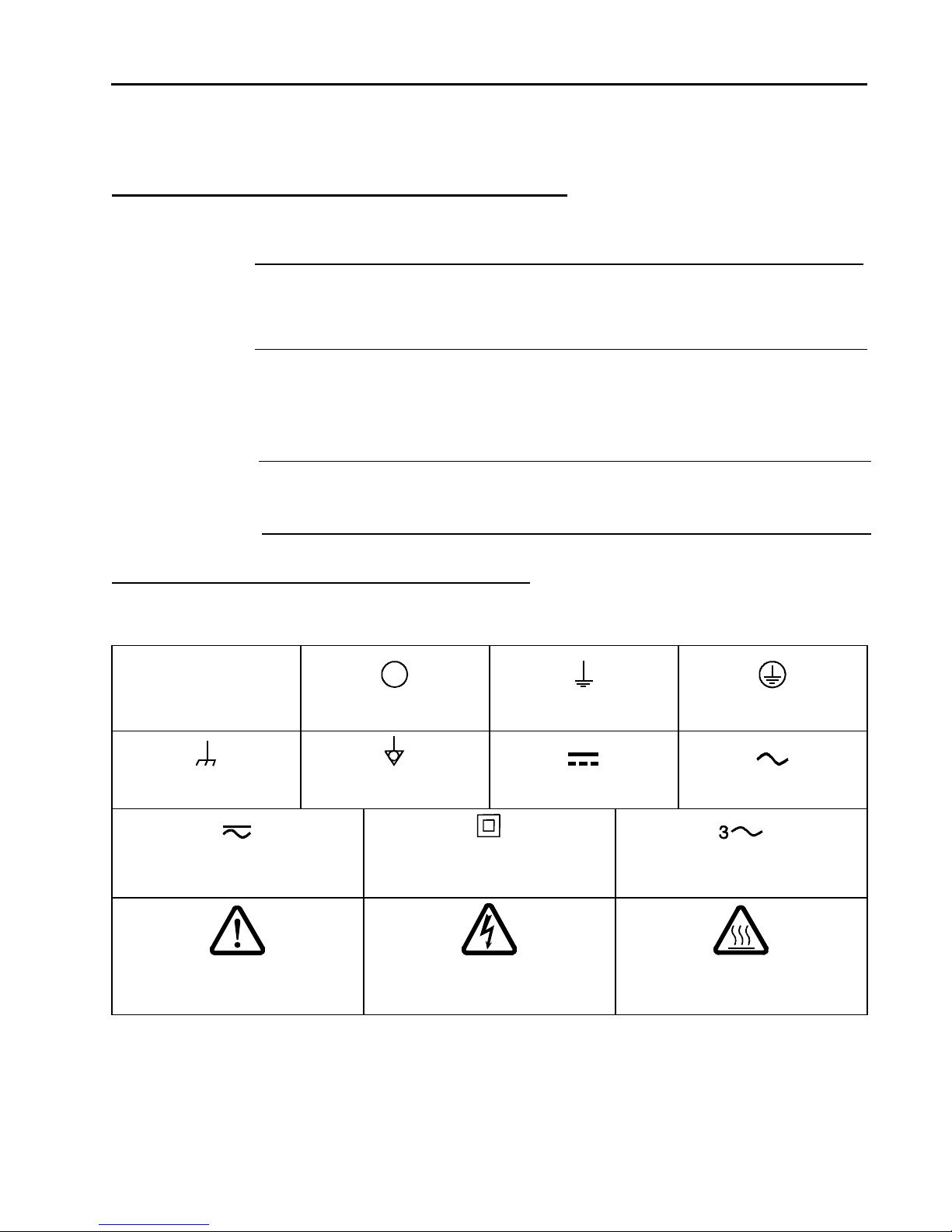
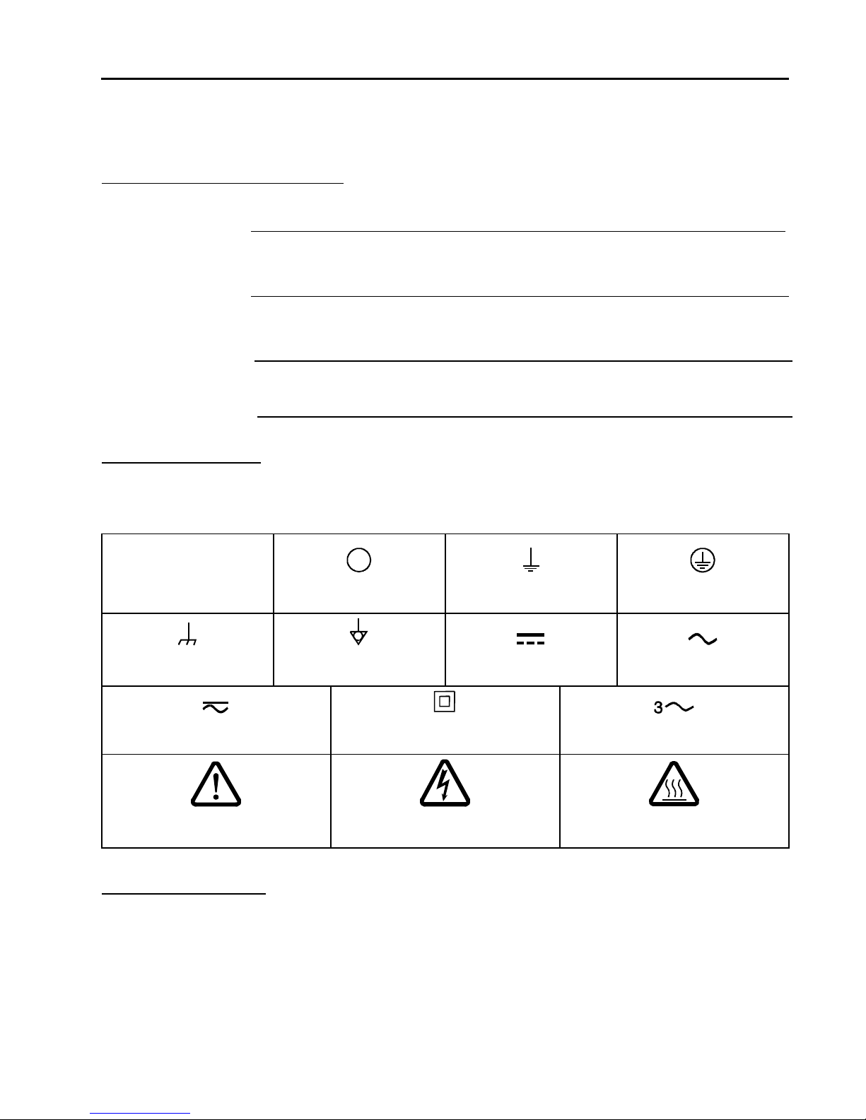
|
Ein (Energie)
IEC 417, No.5007
Aus (Energie)
IEC 417, No.5008
Erdanschluss
IEC 417, No.5017
Schutzleiteranschluss
IEC 417, No.5019
Masseanschluss
IEC 417, No.5020
Aquipotentialanschluss
IEC 417, No.5021
Gleichstrom
IEC 417, No.5031
Wechselstrom
IEC 417, No.5032
Gleich- oder Wechselstrom
IEC 417, No.5033-a
Durchgängige doppelte oder
verstärkte Isolierung
IEC 417, No.5172-a
Dreileiter-Wechselstrom (Drehstrom)
IEC 617-2, No.020206
Warnung vor einer Gefahrenstelle
(Achtung, Dokumentation beachten)
ISO 3864, No.B.3.1
Warnung vor gefährlicher
elektrischer Spannung
ISO 3864, No.B.3.6
Höhere Temperatur an leicht
zugänglichen Teilen
IEC 417, No.5041
Sicherheitshinweise für das Massenflussgerät
In dieser Betriebsanleitung vorkommende Symbole
Bedeutung der mit WARNUNG!, VORSICHT! und HINWEIS gekennzeichneten Absätze in dieser
Betriebsanleitung.
Erklärung der am Gerät angebrachten Symbole
Nachstehender Tabelle sind die Bedeutungen der Symbole zu entnehmen, die am Gerät angebracht sein können.
Tabelle 2: Bedeutung der am Gerät angebrachten Symbole
3

Sicherheitshinweise für das Massenflussgerät
Sicherheitsvorschriften und Vorsichtsmaßnahmen
Folgende allgemeine Sicherheitsvorschriften sind während allen Betriebsphasen dieses Gerätes zu
befolgen. Eine Missachtung der Sicherheitsvorschriften und sonstiger Warnhinweise in dieser
Betriebsanleitung verletzt die für dieses Gerät und seine Bedienung geltenden Sicherheitsstandards,
und kann die Schutzvorrichtungen an diesem Gerät wirkungslos machen. MKS Instruments, Inc.
haftet nicht für Missachtung dieser Sicherheitsvorschriften seitens des Kunden.
Niemals Teile austauschen oder Änderungen am Gerät vornehmen!
Ersetzen Sie keine Teile mit baugleichen oder ähnlichen Teilen, und nehmen Sie keine eigenmächtigen Änderungen am
Gerät vor. Schicken Sie das Gerät zwecks Wartung und Reparatur an den MKS-Kalibrierungs- und -Kundendienst ein.
Nur so wird sichergestellt, dass alle Schutzvorrichtungen voll funktionsfähig bleiben.
Wartung nur durch qualifizierte Fachleute!
Das Auswechseln von Komponenten und das Vornehmen von internen Einstellungen darf nur von qualifizierten
Fachleuten durchgeführt werden, niemals vom Bedienpersonal.
Vorsicht vor stromführenden Leitungen!
Ersetzen Sie keine Komponente von Geräten, die an Netzstrom angeschlossen sind. Unter Umständen kann gefährliche
Spannung auch dann bestehen, wenn das Netzanschlusskabel von der Strmversorgung entfernt wurde. Um Verletzungen
vorzubeugen sollten zuerst alle Geräte von der Stromversorgung getrennt und alle Stromkreusläufe entladen werden.
Vorsicht beim Arbeiten mit gefährlichen Stoffen!
Wenn gefährliche Stoffe verwendet werden, muss der Bediener die entsprechenden Sicherheitsvorschriften genauestens
einhalten, das Gerät, falls erforderlich, vollständig spülen, sowie sicherstellen, dass der Gefahrstoff die am Gerät
verwendeten Materialien, insbesondere Dichtungen, nicht angreift.
Spülen des Gerätes mit Gas!
Nach dem Installieren oder vor dem Ausbau aus einem System muss das Gerät unter Einsatz eines reinen Trockengases
vollständig gespült werden, um alle Rückstände des Vorgängermediums zu entfernen.
Anweisungen zum Spülen des Gerätes
Das Gerät darf nur unter einer Ablufthaube gespült werden. Schutzhandschuhe sind zu tragen.
Gerät nicht zusammen mit explosiven Stoffen, Gasen oder Dämpfen benutzen!
Um der Gefahr einer Explosion vorzubeugen, darf dieses Gerät niemals zusammen mit (oder in der Nähe von)
explosiven Stoffen aller Art eingesetzt werden, sofern es nicht ausdrücklich für diesen Zweck zugelassen ist.
Anweisungen zum Installieren der Armaturen!
Alle Anschlussstücke und Armaturenteile müssen mit der Gerätespezifikation übereinstimmen, und mit dem geplanten
Einsatz des Gerätes kompatibel sein. Der Einbau, insbesondere das Anziehen und Abdichten, muss gemäß den
Anweisungen des Herstellers vorgenommen werden.
Verbindungen auf Undichtigkeiten prüfen!
Überprüfen Sie sorgfältig alle Verbindungen der Vakuumkomponenten auf undichte Stellen.
Gerät nur unter zulässigen Anschlussdrücken betreiben!
Betreiben Sie das Gerät niemals unter Drücken, die den maximal zulässigen Druck (siehe Produktspezifikationen)
übersteigen.
Geeignete Berstscheibe installieren!
Wenn mit einer unter Druck stehenden Gasquelle gearbeitet wird, sollte eine geeignete Berstscheibe in das
Vakuumsystem installiert werden, um eine Explosionsgefahr aufgrund von steigendem Systemdruck zu vermeiden.
Verunreinigungen im Gerät vermeiden!
Stellen Sie sicher, dass Verunreinigungen jeglicher Art weder vor dem Einsatz noch während des Betriebs in das
Instrumenteninnere gelangen können. Staub- und Schmutzpartikel, Glassplitter oder Metallspäne können das Gerät
dauerhaft beschädigen oder Prozess- und Messwerte verfälschen.
Bei Geräten mit Temperaturkontrolle korrekte Anwärmzeit einhalten!
Temperaturkontrollierte Geräte arbeiten nur dann gemäß ihrer Spezifikation, wenn genügend Zeit zum Erreichen und
Stabilisieren der Betriebstemperatur eingeräumt wird. Kalibrierungen und Nulleinstellungen sollten daher nur nach
Abschluss des Anwärmvorgangs durchgeführt werden.
4
Informations de sécurité pour appareils de mesure/contrôle de débit massique
Avertissement
L'indication AVERTISSEMENT signale un danger pour le personnel. Elle
attire l'attention sur une procédure, une pratique, une condition, ou toute
autre situation présentant un risque d'accident pour le personnel, en cas
d'exécution incorrecte ou de non-respect des consignes.
Attention
L'indication ATTENTION signale un danger pour l'appareil. Elle attire
l'attention sur une procédure d'exploitation, une pratique, ou toute autre
situation, présentant un risque de dégât ou de destruction partielle ou totale
du produit, en cas d'exécution incorrecte ou de non-respect des consignes.
Remarque
L'indication REMARQUE signale une information importante. Elle attire
l'attention sur une procédure, une pratique, une condition, ou toute autre situation,
présentant un intérêt particulier.
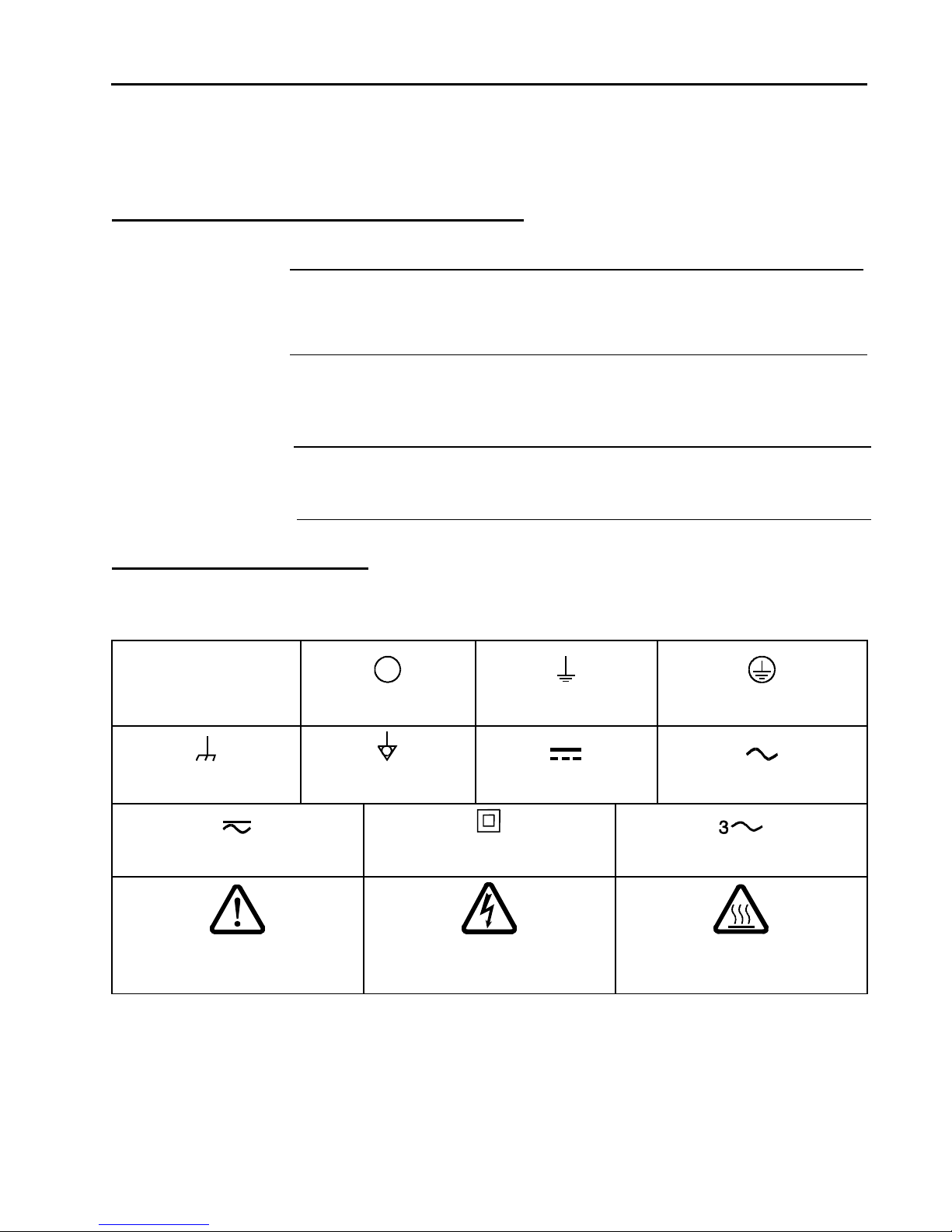
|
Marche (sous tension)
IEC 417, No.5007
Arrêt (hors tension)
IEC 417, No.5008
Terre (masse)
IEC 417, No.5017
Terre de protection (masse)
IEC 417, No.5019
Masse
IEC 417, No.5020
Equipotentialité
IEC 417, No.5021
Courant continu
IEC 417, No.5031
Courant alternatif
IEC 417, No.5032
Courant continu et alternatif
IEC 417, No.5033-a
Matériel de classe II
IEC 417, No.5172-a
Courant alternatif triphasé
IEC 617-2, No.020206
Attention : se reporter
à la documentation
ISO 3864, No.B.3.1
Attention : risque de
choc électrique
ISO 3864, No.B.3.6
Attention : surface brûlante
IEC 417, No.5041
Informations de sécurité pour appareils de mesure/contrôle de débit
massique
Symboles utilisés dans ce manuel d'utilisation
Définitions des indications AVERTISSEMENT, ATTENTION, et REMARQUE utilisées dans ce manuel.
Symboles figurant sur l'unité
Le tableau suivant décrit les symboles pouvant apparaître sur l'unité.
Tableau 3: Définition des symboles sur l'unité
5

Informations de sécurité pour appareils de mesure/contrôle de débit massique
Mesures de sécurité et précautions
Observer les précautions générales de sécurité suivantes pendant toutes les phases d'exploitation de cet
appareil. Le non-respect des ces précautions ou des avertissements du manuel constitue une violation
des normes de sécurité relatives à l'utilisation de l'appareil et peut compromettre la protection assurée
par l'appareil. MKS Instruments, Inc. rejette toute responsabilité en cas de non-respect des consignes
par les clients.
PAS DE REMPLACEMENT DE PIÈCES OU DE MODIFICATION DE L'APPAREIL
Ne pas installer de pièces de remplacement ni effectuer des modifications non autorisées sur l'appareil. Renvoyer
l'appareil à un centre de service et de calibrage MKS pour tout dépannage ou réparation afin de garantir le l'intégrité des
dispositifs de sécurité.
DÉPANNAGE UNIQUEMENT PAR DU PERSONNEL QUALIFIÉ
Le personnel d'exploitation ne doit pas essayer de sortir les composants du boîtier ou faire des réglages internes. Le
dépannage est réservé au personnel qualifié.
ÉLOIGNEMENT DES CIRCUITS SOUS-TENSION
Ne pas remplacer de composants lorsqu’un câble d’alimentation est branché. Dans certaines conditions, des tensions
dangereuses peuvent être présentes même après le retrait du câble d’alimentation. Pour éliminer tout risque de blessure,
procéder toujours à la déconnexion et décharger les circuits avant tout contact physique.
PRÉCAUTION EN CAS D'UTILISATION AVEC DES PRODUITS DANGEREUX
Si des produits dangereux sont utilisés, l'utilisateur est responsable du respect des mesures de sécurité appropriées, de la
purge complète de l'appareil quand elle s’avère nécessaire, et doit s’assurer que les produits utilisés sont compatibles
avec les matériaux d'étanchéité.
PURGE DE L'APPAREIL
Après l'installation de l'unité, ou avant son retrait d'un système, purger l'unité complètement avec un gaz propre et sec
afin d'éliminer toute trace du produit de flux utilisé précédemment.
UTILISATION DES PROCÉDURES APPROPRIÉES POUR LA PURGE
Cet appareil doit être purgé sous une hotte de ventilation. Le personnel doit porter des gants de protection.
PAS D'EXPLOITATION DANS UN ENVIRONNEMENT EXPLOSIF
Pour éviter toute explosion, ne pas utiliser cet appareil dans un environnement explosif, sauf en cas d'homologation
spécifique pour une telle exploitation.
UTILISATION D'ÉQUIPEMENTS ET PROCÉDURES DE SERRAGE APPROPRIÉS
Tous les équipements de l'appareil doivent être conformes à ses spécifications, et compatibles avec l'utilisation prévue de
l'appareil. Assembler et serrer les équipements conformément aux directives du fabricant.
VÉRIFICATION DE L'ÉTANCHÉITÉ DES CONNEXIONS
Vérifier attentivement toutes les connexions des composants pour le vide afin de garantir l'étanchéité de l'installation.
EXPLOITATION AVEC DES PRESSIONS D'ENTRÉE NON DANGEREUSES
Ne jamais utiliser des pressions supérieures à la pression nominale maximum (se reporter aux spécifications de l'unité
pour la pression maximum admissible).
INSTALLATION D'UN DISQUE D'ÉCHAPPEMENT ADAPTÉ
En cas d'exploitation avec une source de gaz pressurisé, installer un disque d'échappement adapté dans le système à vide,
afin d'éviter une explosion du système en cas d'augmentation de la pression.
MAINTIEN DE L'UNITÉ À L'ABRI DES CONTAMINATIONS
Ne pas laisser des produits contaminants pénétrer dans l'unité avant ou pendant l'utilisation. Des produits contaminants
tels que des poussières et des fragments de tissu, de verre et de métal peuvent endommager l'unité de manière
permanente.
RESPECT DU TEMPS D'ÉCHAUFFEMENT APPROPRIÉ POUR LES UNITÉS Á RÉGULATION DE TEMPÉRATURE
Les unités à régulation de température sont conformes à leurs spécifications uniquement quand on leur laisse un temps
suffisant pour atteindre d'une manière stable la température d'exploitation. Ne pas remettre à zéro ou calibrer l'unité tant
que l'échauffement n'est pas terminé.
6
Medidas de seguridad del dispositivo de flujo de masa
Advertencia
El símbolo de advertencia indica la posibilidad de que se produzcan daños
personales. Pone de relieve un procedimiento, práctica, estado, etc. que en caso
de no realizarse o cumplirse correctamente puede causar daños personales.
Precaución
El símbolo de precaución indica la posibilidad de producir daños al equipo.
Pone de relieve un procedimiento operativo, práctica, etc. que en caso de no
realizarse o cumplirse correctamente puede causar daños o la destrucción total
o parcial del equipo.
Nota
El símbolo de notas indica información de importancia. Este símbolo pone de relieve
un procedimiento, práctica o condición cuyo conocimiento es esencial destacar.
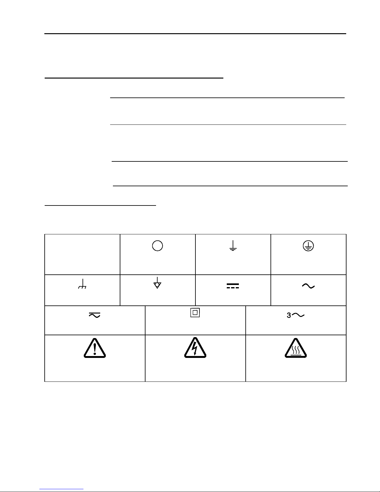
|
Encendido
(alimentación eléctrica)
IEC 417, N° 5007
Apagado
(alimentación eléctrica)
IEC 417, N° 5008
Puesta a tierra
IEC 417, N° 5017
Protección a tierra
IEC 417, N° 5019
Caja o chasis
IEC 417, N° 5020
Equipotencialidad
IEC 417, N° 5021
Corriente continua
IEC 417, N° 5031
Corriente alterna
IEC 417, N° 5032
Corriente continua y alterna
IEC 417, N° 5033-a
Equipo de clase II
IEC 417, N° 5172-a
Corriente alterna trifásica
IEC 617-2, N° 020206
Precaución. Consulte los documentos
adjuntos
ISO 3864, N° B.3.1
Precaución.
Riesgo de descarga eléctrica
ISO 3864, N° B.3.6
Precaución. Superficie caliente
IEC 417, N° 5041
Medidas de seguridad del dispositivo de flujo de masa
Símbolos usados en este manual de instrucciones
Definiciones de los mensajes de advertencia, precaución y de las notas usados en el manual.
Símbolos hallados en la unidad
La tabla siguiente contiene los símbolos que puede hallar en la unidad.
Tabla 4: Definición de los símbolos hallados en la unidad
7

Medidas de seguridad del dispositivo de flujo de masa
Procedimientos y precauciones de seguridad
Las medidas generales de seguridad descritas a continuación deben observarse durante todas las etapas
de funcionamiento del instrumento. La fP250A de cumplimiento de dichas medidas de seguridad o de
las advertencias específicas a las que se hace referencia en otras partes de este manual, constituye una
violación de las normas de seguridad establecidas para el uso previsto del instrumento y podría anular
la protección proporcionada por el equipo. Si el cliente no cumple dichas precauciones y advertencias,
MKS Instruments, Inc. no asume responsabilidad legal alguna.
NO UTILICE PIEZAS NO ORIGINALES O MODIFIQUE EL INSTRUMENTO
No instale piezas que no sean originales ni modifique el instrumento sin autorización. Para asegurar el correcto funcionamiento de
todos los dispositivos de seguridad, envíe el instrumento al Centro de servicio y calibración de MKS toda vez que sea necesario
repararlo o efectuar tareas de mantenimiento.
LAS REPARACIONES DEBEN SER EFECTUADAS ÚNICAMENTE POR TÉCNICOS AUTORIZADOS
Los operarios no deben retirar las tapas del instrumento. El reemplazo de los componentes y las tareas de ajuste deben ser realizadas
únicamente por personal autorizado.
MANTÉNGASE ALEJADO DE LOS CIRCUITOS ACTIVOS
No reemplace componentes con el cable de alimentación eléctrica conectado. En algunos casos, puede haber presente alto voltaje aun
con el cable de alimentación eléctrica desconectado. Para evitar lesiones personales, desconecte siempre el cable y descargue los
circuitos antes de entrar en contacto con los mismos.
TENGA CUIDADO CUANDO TRABAJE CON MATERIALES TÓXICOS
Cuando se utilicen materiales tóxicos, es responsabilidad de los operarios tomar las medidas de seguridad correspondientes, purgar
totalmente el instrumento cuando sea necesario y comprobar que el material utilizado sea compatible con los materiales de sellado.
PURGUE EL INSTRUMENTO
Una vez instalada la unidad o antes de retirarla del sistema, purgue completamente la unidad con gas limpio y seco para eliminar todo
resto de la sustancia líquida empleada anteriormente.
USE PROCEDIMIENTOS ADECUADOS PARA REALIZAR LA PURGA
El instrumento debe purgarse debajo de una campana de ventilación y deben utilizarse guantes protectores.
NO HAGA FUNCIONAR EL INSTRUMENTO EN AMBIENTES CON RIESGO DE EXPLOSIÓN
Para evitar que se produzcan explosiones, no haga funcionar este instrumento en un ambiente con riesgo de explosiones, excepto
cuando el mismo haya sido certificado específicamente para tal uso.
USE ACCESORIOS ADECUADOS Y REALICE CORRECTAMENTE LOS PROCEDIMIENTOS DE AJUSTE
Todos los accesorios del instrumento deben cumplir las especificaciones del mismo y ser compatibles con el uso que se debe dar al
instrumento. Arme y ajuste los accesorios de acuerdo con las instrucciones del fabricante.
COMPRUEBE QUE LOS ACCESORIOS SEAN A PRUEBA DE FUGAS
Antes de proceder con la instalación del instrumento, inspeccione cuidadosamente todas las conexiones de las tuberías para comprobar
que hayan sido instaladas a prueba de fugas.
HAGA FUNCIONAR EL INSTRUMENTO CON PRESIONES DE ENTRADA SEGURAS
No haga funcionar nunca el instrumento con presiones superiores a la máxima presión nominal (en las especificaciones del
instrumento hallará la presión máxima permitida).
INSTALE UNA CÁPSULA DE SEGURIDAD ADECUADA
Cuando el instrumento funcione con una fuente de gas presurizado, instale una cápsula de seguridad adecuada en el sistema de vacío
para evitar que se produzcan explosiones cuando suba la presión del sistema.
MANTENGA LA UNIDAD LIBRE DE CONTAMINANTES
No permita el ingreso de contaminantes en la unidad antes o durante su uso. Los productos contaminantes tales como polvo, suciedad,
pelusa, lascas de vidrio o virutas de metal pueden dañar irreparablemente la unidad.
CALIENTE ADECUADAMENTE LAS UNIDADES CONTROLADAS POR MEDIO DE TEMPERATURA
Las unidades controladas por medio de temperatura funcionarán de acuerdo con las especificaciones sólo cuando se las caliente
durante el tiempo suficiente para permitir que lleguen y se estabilicen a la temperatura de operación indicada. No calibre la unidad y
no la ponga en cero hasta que finalice el procedimiento de calentamiento.
8
マスフロー機器の安全に関する情報
警告
この表示を無視して誤った取り扱い (手順や使用方法、条件など) をすると、人が重傷
を負う可能性が想定される内容を示しています。必ずお読みください。
注意
この表示を無視して誤った取り扱い (手順や使用方法など) をすると、 製品が損傷する
可能性が想定される内容を示しています。必ずお読みください。
ポイント
この表示は手順や使用方法、条件などに関する重要な情報が記載されていることを示
しています。必ずお読みください。
|
オン (電源)
IEC 417, No. 5007
オフ (電源)
IEC 417, No. 5008
接地 (アース)
IEC 417, No. 5017
保護接地 (アース)
IEC 417, No. 5019
フレームまたはシャーシ
IEC 417, No. 5020
等電位
IEC 417, No. 5021
直流
IEC 417, No. 5031
交流
IEC 417, No. 5032
直流と交流
IEC 417, No. 5033-a
クラス 2 機器
IEC 417, No. 5172-a
三相交流
IEC 617-2, No. 020206
注意 (付属書を参照)
ISO 3864, No. B.3.1
注意 (感電の危険あり)
ISO 3864, No. B.3.6
注意 (表面が熱くなっています)
IEC 417, No. 5041
マスフロー機器の安全に関する情報
本取扱説明書のマーク
本マニュアルでは警告、注意、ポイントのマークを用いて重要な事項を記載しています。
本機器のマーク
以下の表では、本機器に使用されているマークについて説明いたします。
表 5: 本機器に使用されているマークについて
安全対策について
本機器を使用する際は、必ず以下の安全対策を守ってください。これらの安全対策や本マニュアルの
警告を無視すると、機器本来の用途の安全基準を侵害することになり、機器が提供する保護機能が
損なわれる可能性があります。MKS Instruments, Inc. は、顧客側の安全対策の不履行に対して
は一切責任を負いかねます。
勝手に部品を変えたり、本体を改造しないこと
本機器に代用部品を使用したり、不正な改造を加えないでください。すべての安全システムを正しく機能させるた
めの修理やメンテナンスが必要な場合は、本機器を MKS Calibration and Service Center まで戻してください。
9

マスフロー機器の安全に関する情報
修理は必ず専門の修理サービスを利用すること
オペレータは絶対に本機器を分解しないでください。部品の交換や内部の調整は必ず専門の修理サービスを利
用してください。
電流が通じている回路から切断すること
電源ケーブルを接続したままで部品を交換しないでください。特定の状況では、電源ケーブルを取り外した状態
でも危険な電圧が残っている場合があります。感電などの事故を防ぐため、回路に触れる前に必ず電源から切
断し、放電してください。
危険な材料を使用する場合は慎重に機器を使用すること
危険な材料を使用する場合は、使用者は各自の責任の元で適切な安全対策を講じてください。必要に応じて
本機器を浄化してください。また、使用する材料に対するシーリング材の耐久性を確認してください。
機器を浄化すること
本機器を取り付けた後やシステムから取り外す前に、きれいな乾燥ガスで本機器を浄化し、使用した材料を完
全に取り除いてください。
浄化する場合は適切な手順で行うこと
本機器の浄化は換気フードの下で行う必要があります。また、浄化作業を行う人は必ず手袋を着用してください。
爆発の危険性のある環境で機器を使用しないこと
爆発が起きるのを防ぐため、本機器を爆発の危険性のある環境で使用しないでください。ただし、そのような環境
での使用が特別に保証されている場合は除きます。
適切な金具類を使用し、手順に従って金具の締めを行うこと
金具類は本機器の仕様と一致し、機器本来の用途に適合したものである必要があります。金具類の取り付け
や締めは、製造業者の指示に従ってください。
液体の漏れがないよう接続箇所を確認すること
本機器を設定する前に、すべての配管の接続を慎重に確認し、液体が漏れないようにしてください。
安全なインレット圧力で使用すること
定格の最大圧力を超える圧力の下で本機器を絶対に使用しないでください (最大許容圧力については仕様書
を参照)。
適切なバーストディスクを取り付けること
圧力のかかったガスを使用する場合は、万一システムが爆発した場合にシステムの圧力が上昇するのを防ぐため、
真空システムに適切なバーストディスクを取り付けてください。
本機器に異物やゴミが混入しないようにすること
本機器の使用前または使用中に、ほこりやゴミ、繊維、ガラスの破片、金属片などの異物やゴミが混入しないよ
うにしてください。本機器が損傷する可能性があります。
温度調整された機器を十分に温めてから使用すること
温度調整された機器が適切な作動温度にならないうちに使用すると、仕様通りの動作をしないことがあります。
本機器が十分に温まるまでは目盛りをゼロに合わせたり、較正しないでください。
10

マスフロー機器の安全に関する情報
This page intentionally left blank.
11

질량 유량 장치 안전 정보
경고
경고 표시는 위험을 나타냅니다. 이 표시는 올바르게 수행되거나 지켜지지 않을
경우, 사람에게 상해를 입힐 수 있는 절차, 수행지침, 상태 또는 이와 유사한
상황들에 대한 주의를 환기시킵니다.
주의
주의 표시는 위험을 나타냅니다. 이 표시는 올바르게 수행되거나 지켜지지 않을
경우, 제품의 일부나 전체에 손상이나 파손을 일으킬 수 있는 절차, 수행지침 또는
이와 유사한 상황들에 대한 주의를 환기시킵니다.
참고
참고 표시는 중요한 정보를 나타냅니다. 이 표시는 강조할 만한 주요 절차,
수행지침, 상태 또는 이와 유사한 상황들에 대한 주의를 환기시킵니다.
|
켬 (전원)
IEC 417, No. 5007
끔 (전원)
IEC 417, No. 5008
접지(지면)
IEC 417, No. 5017
보호 접지(지면)
IEC 417, No. 5019
프레임 또는 섀시
IEC 417, No. 5020
등전위성
IEC 417, No. 5021
직류
IEC 417, No. 5031
교류
IEC 417, No. 5032
직류와 교류 모두
IEC 417, No. 5033-a
클래스 II 장비
IEC 417, No. 5172-a
3상 교류
IEC 617-2, No. 020206
주의 (동봉 문서 참조)
ISO 3864, No. B.3.1
주의, 감전 위험
ISO 3864, No. B.3.6
주의, 표면이 뜨거움
IEC 417, No. 5041
질량 유량 장치 안전 정보
본 지침 매뉴얼에 사용되는 기호들
매뉴얼 전체에 사용되는 경고, 주의 및 참고 메시지의 정의.
장치에 표시된 기호들
다음 표는 장치에서 볼 수 있는 기호들을 설명합니다.
표 6: 장치에 표시된 기호들의 정의
안전 절차 및 예방조치
본 기계의 모든 작동 시에 다음의 일반 안전 예방조치를 준수하십시오. 아래 예방조치를
준수하지 않거나 본 매뉴얼의 다른 부분에 있는 특정 경고를 준수하지 않을 경우, 기계
사용 목적의 안전 기준을 위반하는 것이 되며, 장비가 제공하는 보호기능을 손상시킬 수
있습니다. MKS Instruments, Inc.는 고객이 본 요건을 준수하지 않는 경우에 대해서는
어떠한 책임도 지지 않습니다.
부품을 교체하거나 기계를 개조하지 마십시오
13

질량 유량 장치 안전 정보
교체 부품을 설치하거나 기계에 허가되지 않은 어떠한 수정도 가하지 마십시오. 서비스와 수리가
필요한 경우에는 모든 안전 특성이 유지되도록 기계를 MKS 보정 서비스 센터(MKS Calibration and
Service Center)로 보내주십시오.
자격이 있는 사람에게만 서비스를 받으십시오
작동하는 사람은 기계 겉면을 제거해서는 안됩니다. 부품 교체 및 내부 조정은 자격이 있는 서비스
기사에게만 받으실 수 있습니다.
전류가 통하는 회로에서 분리해 보관하십시오
전원 케이블을 연결한 채로 부품을 교체하지 마십시오. 일부 환경에서는 전원 케이블을 제거한
상태라도 위험 전압이 존재할 수 있습니다. 부상을 방지하려면, 전원을 항상 분리하고 회로를
만지기 전에 회로를 방전시키십시오.
위험한 물질과 함께 작동할 때는 주의를 기울이십시오
위험한 물질이 사용되는 경우, 사용자는 필요시 기계를 완전히 청소하여, 적절한 안전 예방조치를
준수할 책임을 지키고, 사용된 물질이 봉인 물질과 함께 사용해도 무방하다고 보증할 수 있어야
합니다.
기계를 청소하십시오
장치를 설치한 후나 시스템에서 장치를 제거하기 전에는 반드시 깨끗한 건조성 기체로 장치를
완전히 청소하여 이전에 사용된 유량 물질의 모든 흔적을 제거하십시오.
청소 시에는 적절한 절차를 사용하십시오
본 기계는 환기 후드 아래에서 청소되어야 하며, 인체 보호를 위해 장갑을 착용해야 합니다.
폭발성 환경에서 작동하지 마십시오
폭발을 방지하려면, 폭발성 환경에서 작동하도록 특별히 승인받지 않은 경우 본 제품을 폭발성
환경에서 작동하지 마십시오.
적절한 조립부품과 조임 절차를 사용하십시오
모든 기계 조립부품은 제품 사양과 일치해야 하고, 기계의 사용 목적에 부합해야 합니다.
제조업체의 지시에 따라 조립부품을 조립하고 조이십시오.
누출방지 조립부품을 점검하십시오
기계 설치를 진행하기 전에 기계의 모든 연관 연결부를 점검해 누출방지 설치가 되었는지
확인하십시오.
안전한 흡입 압력에서 작동하십시오
이 장치는 절대 정격 최대 압력보다 높은 압력에서 작동해서는 안됩니다(최대 허용 압력에
대해서는 제품 사양을 참조하십시오).
적합한 안전 파열판을 설치하십시오
가압 가스 공급원에서 작동시, 시스템 폭발이 시스템 압력 상승을 일으키는 것을 방지하기 위해
적합한 안전 파열판이 진공 시스템에 설치되어야 합니다.
장치를 오염이 없는 곳에 보관하십시오
장치를 사용하기 전이나 사용 중에는 어떠한 종류의 오염 물질도 허용해서는 안됩니다. 먼지, 때,
보풀, 유리 조각, 금속 조각과 같은 오염 물질은 영구적으로 장치를 손상시킬 수 있습니다.
온도 제어 장치의 경우 알맞은 시동 시간을 두십시오
온도 제어 장치는 장치가 설계 작동 온도와 일치하고 이 온도에서 안정화될 수 있도록 충분한
시간을 허용해야만 사양에 맞게 작동합니다. 시동이 완료될 때까지 장치를 영점 설정하거나
보정하지 마십시오.
14

질량 유량 장치 안전 정보
This page intentionally left blank.
.
15


.
How This Manual is Organized
How This Manual is Organized
This manual is designed to provide instructions on how to set up, install, and operate a P250A / IM250A High
Flow Rate Mass Flow Controllers.
Before installing your P250A / IM250A High Flow Rate Mass Flow Controller in a system and/or
operating it, carefully read and familiarize yourself with all precautionary notes in the Mass Flow
Controller Safety Information section at the front of this manual. In addition, observe and obey all
WARNING and CAUTION notes provided throughout the manual.
Chapter One: General Information introduces the product and describes the basic theory of operation.
Chapter Two: Installation explains the environmental requirements and describes how to mount the
instrument in your system.
Chapter Three: Operation describes how to use the instrument and explains all the functions and features.
Chapter Four: Maintenance and Troubleshooting lists any maintenance required to keep the instrument in
good working condition and provides a reference should the instrument malfunction.
Chapter Five: Dianostic Interface Setup, Configuration, and Operation provides information on how to set
up the instrument’s auxiliary EtherNet diagnostics and monitoring interface. It also provides information on
how to monitor and troubleshoot the device using the instrument’s internal HTML server.
Appendix A: Product Specifications lists the specifications of the instrument.
Appendix B: Model Code Explanation describes the model code.
Appendix C: Health and Safety Form provides a copy of the form at the time of this manual’s release.
17

Chapter One: General Information
Introduction
Chapter One: General Information
Introduction
MKS Instruments P250A High Flow Rate Mass Flow Controller represents a state-of-the-art technology
meeting the advanced process requirements of next generation toolsets. This MFC integrates thermal sensor
technology together with MKS real-time feedback control system to provide typical flow control response
times of approximately 2 seconds.
The P250A MFC includes an integrated multifunctional local display and an embedded, web-based user
interface. The device is available with full scale flow ranges of 100 slm to 250 slm (N2 equivalent) in
standard 8 VCR process connections. Both analog I/O and digital communications protocols are available and
selectable as an option
MKS Instruments IM250A High Flow Rate Mass Flow Controller provides IP66 compliance against water
and dust ingress for critical industrial processes.
Design Features
Increases Throughput and Performance
Accurate flow control for both the calibration and the user selected gas.
Enables better chamber matching through increased MFC accuracy of any process gas.
Increases tool uptime through reduction of “No Problem Found” MFC replacements.
Includes embedded diagnostics software that allows users to check MFC functionality without
removing the MFC.
E-diagnostics through embedded Ethernet interface.
Reduce Overall Costs
Reduces MFC inventory through multi-gas, multi-range availability.
Minimizes overall footprint of gas delivery module.
Easy to Integrate and Operate
Straightforward configuration and diagnostics through Ethernet user interface with standard HTML
browser technology
Easy viewing of flow rate, gas type, full scale and Ethernet address via its LED display.
How the MFC Works
The MFC compares the actual flow reading from an advanced 2-element thermal flow sensor to the desired
setpoint flow rate, and positions the proportional control valve to maintain, or achieve, the desired setpoint
flow rate.
Assume that your MFC is positioned upstream of the process chamber. The MFC is positioned before the
chamber so it will regulate the flow rate of the gas entering the process chamber.
When the actual flow rate reading is less than the setpoint value, the MFC opens the valve to increase the
amount of gas entering the system. As the valve opens, assuming adequate differential pressure across the
flow controller, gas enters the process chamber, so the flow rate rises to meet the setpoint value.
When the actual flow rate reading is more than the setpoint value, the MFC closes the valve to decrease the
amount of gas entering the system. As the valve closes, there is a reduced flow of gas entering the process
chamber, so the flow rate decreases to meet the setpoint value.
18

Operation of the MFC with Gases other than Nitrogen
Chapter One: General Information
Note
The MFC must have sufficient differential pressure from inlet to outlet to achieve the setpoint.
If the device does not reach setpoint for lack of differential pressure, either increasing the inlet
pressure or decreasing the outlet pressure may be necessary.
Note
For optimal control performance, the user should specify the inlet pressure provided to the MFC
through the Ethernet user interface.
Upon entering the MFC, the process gas stream passes first through the metering section of the instrument for
its mass flow rate to be measured.
The metering section consists of a small bore sensor tube operating in parallel with a precision formed bypass.
The geometry of the sensor tube, in conjunction with the specified full scale flow rate, ensures fully
developed laminar flow in the sensing region. The bypass elements are specifically matched to the
characteristics of the sensor tube to achieve a laminar flow splitting ratio which remains constant throughout
each range.
The flow measurement is based on differential heat transfer between temperature sensing heater elements
which are attached to the exterior of a small bore sensor tube. The bridge circuitry senses the thermal mass
movement which is converted to mass flow via the specific heat, Cp, of the gas. A low temperature effect
from ambient temperature change and minimal attitude sensitivity effect are also ensured. Attitude sensitivity
is completely accounted for with advanced attitude circuitry. The optimized sensor/bypass arrangement
minimizes the flow splitting error for gases with different properties, which dramatically improves
measurement accuracy when gases other than the calibration gas are used.
The controller employs the above measurement technique and utilizes a control circuit that provides drive
current for the proportioning control valve. The flow controller accepts a setpoint signal, compares it to its
own flow signal, and generates an error voltage. This error signal is then conditioned, using a model based
control algorithm, so that it can reposition the control valve, thus reducing the control error to zero. Real-time
accurate flow control is provided through advanced digital algorithms. Enabling real-time control of process
gas flow, accuracy and repeatability are significantly improved over conventional PID based digital MFC’s.
The control valve is a specially constructed solenoid valve in which the armature (moving valve mechanism)
is suspended. The arrangement ensures that minimal friction is present and makes precise control possible. In
the normally closed control valve, the MFC instrument lifts the armature and plug assembly from the seat to
regulate the gas flow rate.
The flow exits the instrument at the established rate of flow downstream of the control valve.
Operation of the MFC with Gases other than Nitrogen
The P250A High Flow Rate Mass Flow Controller does not use gas correction factors (as many other mass
flow controllers do) to accurately measure and control process gases other than nitrogen.
The operation of the P250A High Flow Rate Mass Flow Controller multi-gas, multi-range functionality is
based on thermodynamic principals and multi-component functions that have been developed to accurately
calculate the non-linear gas flow of non-calibration gases, with respect to the calibration gas. The current
MKS library of gases and functions is in excess of 80 in number and includes most gases in common use
within the process industries. For gases whose parameters that are not already stored on the MFC, please
consult an MKS applications engineer.
When a gas other than the calibration gas is selected by the user, the MFC automatically pulls up the correct
functions that calculate the flow of that gas with respect to the original calibration. This allows the MFC to
report the gas flow for the gas in use immediately and with better accuracy than has previously been available.
19

Chapter One: General Information
Operation of the MFC with Gases other than
Nitrogen
In comparison, the typical MFC uses Gas Correction factors for converting the calibration gas flow into the
flow of the gas being used. This may lead to inaccuracy in the flow reported to levels as high as 6-10% (of
FS) depending on the gas used.
Control (I/O) Interfaces
The P250A High Flow Rate Mass Flow Controller is available with either analog or digital interface I/O
which is specified by the user at time of ordering.
Analog I/O is available via either a 9 pin D or 15 pin D. The 9 pin D option provides for setpoint I/O along
with a valve override function. The 15 pin D option provides for setpoint I/O, valve override and the ability
to control to an optional input. Analog I/O pin functions are covered later in this manual.
The digital control I/O may be via RS485, DeviceNet, or a modified Modbus TCP/IP protocol. An overview
of each along with connector, power supply and switch information is included in this manual. Protocol
specifics (profile) are included in separate documentation.
Cleanliness Features
The P250A High Flow Rate Mass Flow Controller uses only metal for all external seals. The metal seals
eliminate gas permeation and ensure extremely low external leakage. The P250A MFC mechanical design
incorporates minimal wetted surface area and virtual leaks, assuring rapid dry-down. To further enhance its
cleanliness, all internal surfaces are precision machined, electropolished, and subjected to a proprietary
cleaning process under Class 100 conditions. The instrument is assembled and packaged in a Class 100 clean
room environment.
Reliability
To provide excellent reliability, the design contains a low mechanical and electronic components count and
has successfully passed the following test:
STRIFE, including temperature cycling and vibration (sine and random tests)
And with a metal braided, shielded cable, properly grounded at both ends:
EMC Directive 89/336/EEC for CE Mark compliance
20
 Loading...