

MKS HPS 937A Maintance Manual

HPSTM Series 937A
High V acuum
Multi-Sensor System
OPERATION AND
MAINTENANCE MANU AL


HPS
TM
Series 937 A
High Vacuum
Multi-Sensor System
August 1998
Part # 100009273 Rev. 4.0

Part # 937A- __ __ __ __ __ __ __ __ - __ __ __ __ __ __ - __ __ __
Serial # __ __ __ __ __ __
Please fill in these numbers and have them readily available when
calling for service or additional information.
(The part number can be found on your packing slip, and the serial
number is located on the rear of the housing.)
For more information or literature, contact:
MKS Instruments, Inc., V acuum Products Gr oup
5330 Sterling Drive
Boulder , CO 80301 USA
Phone: 303-449-9861
800-345-1967
F AX: 303-442-6880
© 1998 by MKS Instruments, Inc., Vacuum Products Group, All rights reserved.
ALCONOX is a registered trademark of Alconox, Inc.
Baratron is a registered trademark of MKS Instruments, Inc.
Elgiloy is a registered trademark of Elgiloy Co.
HPS and IgniTorr are trademarks and I-MA G is a registered trademark of MKS Instruments, Inc., Vacuum Products Group
Inconel is a registered trademark of Inco Alloys International, Inc.
Scotch-Brite is a trademark of 3M.
Teflon and Viton are a registered trademarks of DuP ont Co.
VCR is a registered trademark of Cajon Co.

TABLE OF CONTENTS
TABLE OF CONTENTS
PACKAGE CONTENTS ...................................................................... 1
SAFETY INFORMATION...................................................................... 2
Symbols............................................................................................ 2
Symbols Used in this Manual (English).............................................................. 2
Symboles utilisés dans ce manuel (Français) .................................................. 2
In dieser Betriebsanleitung vorkommende Symbole (Deutsch) ....................... 3
Símbolos Usados en el Manual (Español) ......................................................... 3
Symbol Definitions............................................................................ 4
Definition of Symbols Found on the Unit (English) ............................................ 4
Définition des symboles apparaissant sur l’appareil (Français) .................... 4
Definitionen der am Gerät angebrachten Symbole (Deutsch) ......................... 5
Símbolos que Aparecen en la Unidad (Español)............................................... 5
Safety Precautions ........................................................................... 6
Safety Procedures and Precautions (English) .................................................. 6
Sicherheitsvorschriften und Vorsichtsmaßnahmen (Deutsch) ....................... 10
Procedimientos y Precauciones de Seguridad (Español) .............................. 12
SPECIFICATIONS*.......................................................................... 14
Controller .........................................................................................14
Sensors ...........................................................................................17
FEATURE AND CONTROL LOCATIONS................................................. 22
TYPICAL APPLICATIONS FOR THE SERIES 937A .................................. 24
HPS™ Products Series 937A Multi-Sensor High
Vacuum System ...................................................................... 25
Set Points........................................................................................26
Leak T est .........................................................................................2 6
Analog Output Signals .....................................................................26
Computer Interface ..........................................................................26
Setting Up the Series 937A Controller .................................... 27
Removing a Modu le .........................................................................27

Configuring a Module .......................................................................2 7
Sensor Modules ................................................................................................. 27
Cold Cathode ............................................................................................. 28
Pirani........................................................................................................... 28
Convection Pirani ....................................................................................... 29
Capacitance Manometer ........................................................................... 29
Thermocouple ............................................................................................ 30
Analog Module .................................................................................................... 30
Pressure Units – Switches 1 and 2 .......................................................... 30
Control/Combination Sensor Channels– Switches 3 and 4.................... 30
Line Frequency – Switch 5 ....................................................................... 31
Cold Cathode Sensor Delay – Switch 6 ................................................... 31
Configuration-Switch 7 .............................................................................. 31
UCAL Enable/Disable ................................................................................ 31
RS-232/RS-485 Communications Module (Optional) ...................................... 31
Power Supply Module ........................................................................................ 33
Installing a Module ............................................................................................. 33
Panel Labels ....................................................................................................... 34
Mounting the Controller ............................................................................. 34
AC Power Cord .......................................................................................... 35
OPERATING THE SERIES 937A CONTROLLER ..................................... 36
Power ...............................................................................................36
Display........................................................................................................ 36
Using the Front Panel Controls ................................................................ 38
Using Function Select......................................................................39
Display Test Mode ............................................................................................. 39
Reviewing Controller Setup ............................................................................... 39
Setup Review Screen 1............................................................................. 39
Cold Cathode non-Standard Configuration Codes................................. 40
Setup Review Screen 2............................................................................. 41
Setup Review Screen 3............................................................................. 41
Setup Review Screen 4............................................................................. 42
Setup Review Screen 5............................................................................. 42
Setup Review Screen 6............................................................................. 42
Setup Review Screen 7............................................................................. 43
Pressure Mode ................................................................................................... 43
Cold Cathode Sensor High Voltage ..................................................44
Front Panel Control Lock .................................................................................. 44
Leak Test Mode .......................................................................................... 45
Relay Set Points Mode .............................................................................. 46
Reading a Relay Set Point ......................................................................... 46
Setting a Relay Set Point ........................................................................... 46
Disabling a Relay Set Point ....................................................................... 47
Relay Inductive Loads and Arc Suppression .......................................... 47
Protection and Control Set Points Mode................................................... 48
Setting a Protection Set Point.................................................................... 48
Setting a Control Set Point ......................................................................... 48
Protection and Control Set Point Display Messages ....................................... 49
Protection and Control Set Point Messages ............................................ 49
Disabling a Protection or Control Set Point.............................................. 50
Zero and ATM Calibration Modes ............................................................. 50
Zero Calibration Mode ............................................................................... 51
Capacitance Manometer Auto-Zero Feature ........................................... 52
ATM Calibration Mode ............................................................................... 53
Calibrating the Convection Pirani Sensor for Atmosphere ..................... 54
Method 1 ..................................................................................................... 54
Method 2 ..................................................................................................... 54
Cold Cathode Operation .................................................................................... 55

C.C. On/C.C. Off Front Panel Push-Buttons............................................ 56
Cold Cathode Module Remote Connector ............................................... 56
Analog Module............................................................................................ 56
Communications Module (optional) .......................................................... 56
Using Protection and Control Set Points .................................................. 57
Determining Protection and Control Set Points........................................ 58
Information Update Rate .................................................................................... 59
Controller Analog Output ................................................................................... 60
Buffered Output ......................................................................................... 60
Logarithmic Output .................................................................................... 61
Combination Logarithmic Output .............................................................. 62
Error Messages ................................................................................................. 63
Main Program Checksum Test ................................................................. 63
Communications Module Program Checksum Test ................................ 63
Nonvolatile Memory Error in Correction Factors..................................... 63
Setup Error ................................................................................................. 64
Quick Reference Tables ...................................................................65
Table I Front Panel Operation ................................................................... 65
Table II Setpoint Values ............................................................................. 66
Relay S etpoints .......................................................................................... 66
Control Setpoints ....................................................................................... 66
Protection Setpoint ..................................................................................... 66
SPARE PARTS AND ACCESSORIES .................................................... 67
PRODUCT WARRANTY ................................................................... 70
Notes....................................................................................... 71
APPENDIX A: INSTALLING A SERIES 937A SENSOR ............................ A.1
Cold Cathode Sensors ................................................................... A.1
General.............................................................................................................. A.1
Locating a Cold Cathode Sensor ..................................................................... A.1
Orienting a Cold Cathode Sensor .................................................................... A.1
Managing Contamination in a Cold Cathode Sensor ...................................... A.2
Testing a Cold Cathode Sensor ....................................................................... A.2
Series 423 I-MAG® Cold Cathode Sensor ..................................................... A.2
Connecting the I-MAG Sensor ................................................................. A.2
Disassembling the I-MAG Sensor ........................................................... A.2
Cleaning the I-MAG Sensor ..................................................................... A.3
Assembling the I-MAG Sensor ................................................................ A.5
Preparing the Sensor for Bakeout ........................................................... A.6
Series 421 Cold Cathode Sensor .................................................................... A.6
Connecting the Series 421 Sensor.......................................................... A.6
Disassembling the Series 421 Sensor .................................................... A.6
Cleaning the Series 421 Sensor .............................................................. A.8
Assembling the Series 421 Sensor ......................................................... A.9
Preparing the Sensor for Bakeout ........................................................... A.9
Pirani Sensors ............................................................................... A.9
General.............................................................................................................. A.9
Locating a Pirani Sensor .................................................................................. A.9
Preventing Contamination in a Pirani Sensor ................................................ A.10
Series 315/345 Pirani Sensor ...................................................... A.10
Orienting the Series 315/345 Pirani Sensor ........................................ A.10
Connecting the Series 315/345 Sensor ............................................... A.10
Cleaning the Series 315/345 Sensor ..................................................... A.12
Testing the Series 315/345 Sensor ............................................................... A.12

Series 317 Convection Pirani Sensor ........................................................... A.12
Orienting the Series 317 Sensor ........................................................... A.12
Connecting the Series 317 Sensor........................................................ A.13
Cleaning the Series 317 Sensor ............................................................ A.15
Testing the Series 317 Sensor ............................................................... A.15
Preparing the 317 Sensor for Bakeout .................................................. A.15
Capacitance Manometer MKS Baratron® .................................... A.16
General............................................................................................................ A.16
Installing the Baratron Capacitance Manometer .......................................... A.16
Connecting the Baratron™ Capacitance Manometer .................................. A.16
Repairing the Baratron™ Capacitance Manometer ..................................... A.17
Thermocouple Sensor .................................................................. A.18
General............................................................................................................ A.18
Orienting the DV-6M Sensor .......................................................................... A.18
Connecting the DV-6M Sensor ....................................................................... A.18
Cleaning the DV-6M Sensor ........................................................................... A.19
APPENDIX B: L EAK TESTING WITH THE SERIES 937A..........................B.1
APPENDIX C: 937A SENSOR OUTPUT VS. PRESSURE CURVES.............C.1
Buffered Analog Output Cold Cathode (Series 421 and 423).......... C.1
Buffered Analog Output Pirani (Series 315 and 345) ......................C.2
Buffered Analog Output Convection Pirani (Series 317)................. C.3
Buffered Analog Output Capacitance Manometer .......................... C. 4
Buffered Analog Output Thermocouple (D V -6M)............................. C.5
Logarithmic and Combination Output All Sensors ..........................C.6
Package Contents
Before unpacking y our Series 937A High V acuum, Multi-Sensor System,
check all surfaces of the package for shipping damage.
Please be sure that your Series 937A System package contains these items:
1 Series 937A Controller (with selected modules installed)
1 female, 9-pin "D" sub
1 10-foot power cord
1
HPS™ Products Series 937A Multi-Sensor High Vacuum System
User's Manual.
If an optional communications module was ordered, a separate manual for the
module should also be included with the package. The Series 937A System's
sensors and their connecting cables are sold separately. Please refer to page
68 for necessary ordering information.
If any items are missing from the package, call HPS™ Products
Customer Service at 1-303-449-9861 or 1-800-345-1967.
Inspect the Series 937A System for visible evidence of damage. If it
has been damaged in shipping, notify the carrier immediately. Keep all
shipping materials and packaging for claim verification. Do not return
the product to MKS.
Accessory
connector kit
937A Multi-Sensor System
1
Safety Information
Symbols
Symbols Used in this
Manual (English)
Definitions of CAUTION and NO TE
messages used throughout the
manual.
CAUTION: Risk of electrical
shock. ISO 3864, No. B.3.6
CAUTION: Refer to
accompanying documents.
ISO 3864, No. B.3.1
This sign denotes a hazard.
It calls attention to a
procedure, practice, condition,
or the like, which, if not
correctly performed or
adhered to, could result in
injury to personnel.
Symboles utilisés dans
ce manuel (Français)
Définition des indications
A TTENTION et REMARQUE
utilisées dans ce manuel.
A TTENTION: Risque de secousse
électrique. ISO 3864, No. B.3.6
ATTENTION: Se reporter à la
documentation.ISO 3864, No. B.3.1
L’indication signale un danger potentiel.
Elle est destinée à attirer l’attention sur
une procédure, une utilisation, une
situation ou toute autre chose
présentant un risque de blessure en
cas d’exécution incorrecte ou de nonrespect des consignes.
This sign denotes a hazard.
It calls attention to an
operating procedure,
practice, or the like, which,
if not correctly performed
or adhered to, could result
in damage to or destruction
of all or part of the product.
This sign denotes
important information. It
calls attention to a
procedure, practice,
condition, or the like, which
is essential to highlight.
2
937A Multi-Sensor System
L’indication signale un danger
potentiel. Elle est destinée à attirer
l’attention sur une procédure, une
utilisation, une situation ou toute autre
chose présentant un risque
d’endommagement ou de dégât d’une
partie ou de la totalité de l’appareil en
cas d’exécution incorrecte ou de nonrespect des consignes.
L’indication REMARQUE signale
des informations importantes. Elle
est destinée à attirer l’attention sur
une procédure, une utilisation, une
situation ou toute autre chose
présentant un intérêt particulier.
In dieser
Betriebsanleitung
vorkommende Symbole
(Deutsch)
Símbolos Usados en el
Manual (Español)
Definition der mit V ORSICHT! und
HINWEIS überschriebenen
Abschnitte in dieser
Betriebsanleitung.
VORSICHT! Str omschlag gefahr!
ISO 3864, Nr. B.3.6
VORSICHT! Bitte
Begleitdokumente lesen! ISO 3864,
Nr . B.3.1
Das Symbol V ORSICHT! weist auf
eine Gefahrenquelle hin. Es macht
auf einen Arbeitsablauf, eine
Arbeitsweise, einen Zustand oder
eine sonstige Gegebenheit
aufmerksam, deren unsachgemäße
Ausführung bzw . Ungenügende
Berücksichtigung zu
Körperverletzung führen kann.
Das Symbol V ORSICHT! weist auf
eine Gefahrenquelle hin. Es macht
auf einen Bedienungsablauf, eine
Arbeitsweise oder eine sonstige
Gegebenheit aufmerksam, deren
unsachgemäße Ausführung bzw .
Ungenügende Berücksichtigung zu
einer Beschädigung oder
Zerstörung des Produkts oder von
T eilen des Produkts führen kann.
Definiciones de los mensajes de
PRECAUCIÓN y OBSER V A CIÓN
usados en el manual.
PRECA UCIÓN: Riesgo de descar ga
eléctrica. ISO 3864, N.° B.3.6
PRECA UCIÓN: Consultar los
documentos adjuntos.
ISO 3864, N.° B.3.1
Esto símbolo indica un riesgo. P one
de reliev e un procedimiento, práctica,
condición, etc., que, de no realizarse
u observarse correctamente, podría
causar lesiones a los empleados.
Esto símbolo indica un riesgo.
Pone de relie ve un
procedimiento, práctica, etc., de
tipo operativo que, de no
realizarse u observarse
correctamente, podría causar
desperfectos al instrumento, o
llegar incluso a causar su
destrucción total o parcial.
Das Symbol HINWEIS weist auf
eine wichtige Mitteilung hin, die
auf einen Arbeitsablauf, eine
Arbeitsweise, einen Zustand oder
eine sonstige Gegebenheit von
besonderer Wichtigkeit
aufmerksam macht.
937A Multi-Sensor System
Esto símbolo indica
información de importancia.
Pone de relieve un
procedimiento, práctica,
condición, etc., cuyo
conocimiento resulta esencial.
3
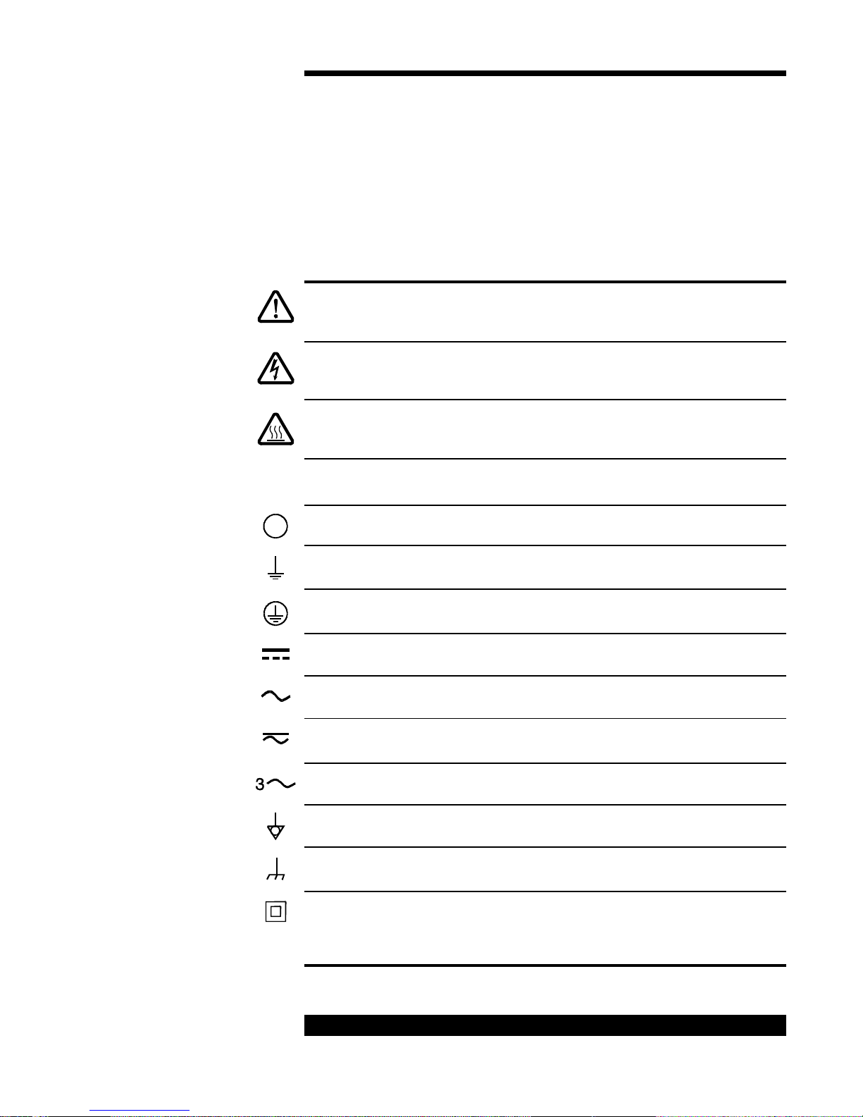
Symbol Definitions
Definition of Symbols
Found on the Unit
(English)
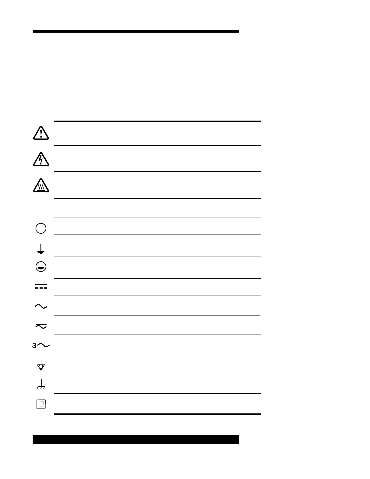
Caution
refer to accompanying documents
ISO 3864, No. B.3.1
Caution
risk of electric shock
ISO 3864, No. B.3.6
Caution
hot surface
IEC 417, No. 5041
On (Supply)
IEC 417, No. 5007
|
Off (Supply)
IEC 417, No. 5008
Earth (Ground)
IEC 417, No. 5017
Définition des symboles
apparaissant sur
l’appareil (Français)
Attention
se reporter à la documentation
ISO 3864, No. B.3.1
Attention
risque de secousse électrique
ISO 3864, No. B.3.6
Attention
surface brûlante
IEC 417, No. 5041
Marche (mise sous tension)
IEC 417, No. 5007
Arrêt (hors tension)
IEC 417, No. 5008
Terre
IEC 417, No. 5017
Protective Earth (Ground)
IEC 417, No. 5019
Direct Current
IEC 417, No. 5031
Alternating Current
IEC 417, No. 5032
Both Direct and Alternating Current
IEC 417, No. 5033-a
Three-phase Alternating Current
IEC617-2, No. 020206
Equipotentiality
IEC 417, No. 5021
Frame or Chassis
IEC 417, No. 5020
Class II Equipment
IEC 417, No. 5172-a
4
937A Multi-Sensor System
Terre de protection
IEC 417, No. 5019
Courant continu
IEC 417, No. 5031
Courant alternatif
IEC 417, No. 5032
Courant continu et alternatif
IEC 417, No. 5033-a
Courant alternatif triphasé
IEC617-2, No. 020206
Equipotentialité
IEC 417, No. 5021
Masse, Châssis
IEC 417, No. 5020
Matériel de la Classe II
IEC 417, No. 5172-a
Definitionen der am
Gerät angebrachten
Symbole (Deutsch)
Símbolos que Aparecen
en la Unidad (Español)
Vorsicht!
Bitte Begleitdokumente lesen!
ISO 3864, Nr. B.3.1
Vorsicht!
Stromschlaggefahr!
ISO 3864, Nr. B.3.6
Vorsicht!
Heiße Fläche!
IEC 417, Nr. 5041
Ein (Netz)
|
IEC 417, Nr. 5007
Aus (Netz)
IEC 417, Nr. 5008
Erde
IEC 417, Nr. 5017
Schutzleiter
IEC 417, Nr. 5019
Gleichstrom
IEC 417, Nr. 5031
Wechselstrom
IEC 417, Nr. 5032
Precaución
Consultar los documentos adjuntos
ISO 3864, N.° B.3.1
Precaución
Riesgo de descarga eléctrica
ISO 3864, N.° B.3.6
Precaución
Superficie caliente
IEC 417, N.° 5041
Encendido (alimentación eléctrica)
IEC 417, N.° 5007
Apagado (alimentación eléctrica)
IEC 417, N.° 5008
Puesta a tierra
IEC 417, N.° 5017
Protección a tierra
IEC 417, N.° 5019
Corriente continua
IEC 417, N.° 5031
Corriente alterna
IEC 417, N.° 5032
Wechselstrom und Gleichstrom
IEC 417, Nr. 5033-a
Drehstrom
IEC 617-2 Nr. 020206
Äquipotentialanschluß
IEC 417, Nr. 5021
Rahmen oder Chassis
IEC 417, Nr. 5020
Geräteklasse II
IEC 417, Nr. 5172-a
937A Multi-Sensor System
Corriente continua y alterna
IEC 417, N.° 5033-a
Corriente alterna trifásica
IEC 617-2 N.° 020206
Equipotencialidad
IEC 417, N.° 5021
Caja o chasis
IEC 417, N.° 5020
Equipo de clase II
IEC 417, N.° 5172-a
5
Safety Precautions
Safety Procedures and Precautions (English)
The following general safety precautions must be observed during all phases
of operation of this instrument. F ailure to comply with these precautions or
with specific warnings elsewhere in this manual violates safety standards of
intended use of the instrument and may impair the protection provided by the
equipment. MKS Instruments, Inc. assumes no liability for the customer’s
failure to comply with these requirements.
Properly ground the Contr oller .
This product is grounded through the grounding conductor of the power cord.
To avoid electrical shoc k, plug the power cord into a properly wired receptacle
before connecting it to the product input or output terminals. A protective
ground connection by way of the grounding conductor in the power cord is
essential for safe operation.
Upon loss of the protective-ground connection, all accessible conductive
parts (including knobs and controls that may appear to be insulating) can
render an electrical shock.
Do not substitute parts or modify instrument.
Do not install substitute parts or perform any unauthorized modification to the
instrument. Return the instrument to an MKS Calibration and Service Center
for service and repair to ensure that all safety features are maintained.
Use proper electrical fittings.
Dangerous voltages are contained within this instrument. All electrical fittings
and cables must be of the type specified, and in good condition. All electrical
fittings must be properly connected and grounded.
The Series 937A Controller contains lethal voltages when on.
High voltage is present in the cable and a cold cathode sensor when the
Controller is turned on.
Use the proper power source.
This product is intended to operate from a power source that applies a voltage
between the supply conductors, or between either of the supply conductors
and ground, not more than that specified in the manual.
Use the proper fuse.
Use only a fuse of the correct type, voltage rating, and current rating, as
specified for your product.
6
937A Multi-Sensor System
Do not operate in explosive en vironments.
To avoid explosion, do not operate this product in an explosive environment
unless it has been specifically certified for such operation.
Service by qualified personnel only.
Operating personnel must not remove instrument covers. Component
replacement and internal adjustments must be made by qualified service
personnel only .
Use the proper power cord.
Use only a power cord that is in good condition and which meets the input
power requirements specified in the manual.
Use only a detachable cord set with conductors that have a cross-sectional
area equal to or greater than 0.75 mm2. The po wer cable should be approv ed
by a qualified agency such as VDE, Semko, or SEV.
937A Multi-Sensor System
7
Mesures de Sécurité et Mises en Garde (Français)
Prendre toutes les précautions générales suivantes pendant toutes les phases
d’utilisation de cet appareil. Le non-respect de ces précautions ou des
avertissements contenus dans ce manuel entraîne une violation des normes
de sécurité relatives à l’utilisation de l’appareil et le risque de réduire le niveau
de protection fourni par l’appareil. MKS Instruments, Inc. ne prend aucune
responsabilité pour les conséquences de tout non-respect des consignes de la
part de ses clients.
Mise à la terre de l'appareil.
Cet appareil est mis à la terre à l’aide du fil de terre du cordon d’alimentation.
Pour éviter tout risque de secousse électrique, brancher le cordon
d’alimentation sur une prise de courant correctement câblée avant de le
brancher sur les bornes d’entrée ou de sortie de l’appareil. Une mise à la terre
de protection à l’aide du fil de terre du cordon d’alimentation est indispensable
pour une utilisation sans danger de l’appareil.
En cas de défaut de terre, toutes les pièces conductrices accessibles (y
compris les boutons de commande ou de réglage qui semblent être isolés)
peuvent être source d’une secousse électrique.
Ne pas substituer des pièces ou modifier l’appareil.
Ne pas utiliser de pièces détachées autres que celles vendues par MKS
Instruments, Inc. ou modifier l’appareil sans l’autorisation préalable de MKS
Instruments, Inc. Renvoyer l’appareil à un centre d’étalonnage et de
dépannage MKS pour tout dépannage ou réparation afin de s’assurer que tous
les dispositifs de sécurité sont maintenus.
Mise à la terre et utilisation correcte d’accessoires électriques.
Des tensions dangereuses existent à l’intérieur de l’appareil. T ous les
accessoires et les câbles électriques doivent être conformes au type spécifié
et être en bon état. Tous les accessoires électriques doivent être correctement
connectés et mis à la terre.
Danger de haute tension.
Une haute tension est présente dans le câble et dans le capteur lorsque le
contrôleur est sous tension.
Utilisation d’une alimentation appropriée.
Cet appareil est conçu pour fonctionner en s’alimentant sur une source de
courant électrique n’appliquant pas une tension entre les conducteurs
d’alimentation, ou entre les conducteurs d’alimentation et le conducteur de
terre, supérieure à celle spécifiée dans le manuel.
Utilisation d’un fusible approprié.
Utiliser uniquement un fusible conforme au type, à la tension nominale et au
courant nominal spécifiés pour l’appareil.
8
937A Multi-Sensor System
Ne pas utiliser dans une atmosphère explosive.
Pour éviter tout risque d’explosion, ne pas utiliser l’appareil dans une
atmosphère explosive à moins qu’il n’ait été approuvé pour une telle
utilisation.
Dépannage effectué uniquement par un personnel qualifié.
L’opérateur de l’appareil ne doit pas enlever le capot de l’appareil. Le
remplacement des composants et les réglages internes doivent être effectués
uniquement par un personnel d’entretien qualifié.
Utilisation d’un cordon d’alimentation approprié.
Utiliser uniquement un cordon d’alimentation en bon état et conforme aux
exigences de puissance d’entrée spécifiées dans le manuel.
Utiliser uniquement un cordon d’alimentation amovible avec des conducteurs
dont la section est égale ou supérieure à 0,75 mm2. Le cordon d’alimentation
doit être approuvé par un organisme compétent tel que VDE, Semk o ou SEV.
937A Multi-Sensor System
9
Sicherheitsvorschriften und Vorsichtsmaßnahmen
(Deutsch)
Die untenstehenden allgemeinen Sicherheitsvorschriften sind bei allen
Betriebs-phasen dieses Instruments zu befolgen. Jede Mißachtung dieser
Sicherheits-vorschriften oder sonstiger spezifischer W arnhinweise in dieser
Betriebsanleitung stellt eine Zuwiderhandlung der für dieses Instrument
geltenden Sicherheits-standards dar und kann die an diesem Instrument
vorgesehenen Schutzvor-richtungen unwirksam machen. MKS Instruments,
Inc. haftet nicht für eine Mißachtung dieser Sicherheitsvorschriften seitens
des Kunden.
Produkt erden!
Dieses Produkt ist mit einer Erdleitung und einem Schutzkontakt am
Netzstecker versehen. Um der Gefahr eines elektrischen Schlages
vorzubeugen, ist das Netzkabel an einer vorschriftsmäßig geerdeten
Schutzkontaktsteckdose anzuschließen, be v or es an den Eingangs- bzw .
Ausgangsklemmen des Produkts angeschlossen wird. Das Instrument kann
nur sicher betrieben werden, wenn es über den Erdleiter des Netzkabels und
einen Schutzkontakt geerdet wird.
Geht die Verbindung zum Schutzleiter verloren, besteht an sämtlichen
zugänglichen Teilen aus stromleitendem Material die Gefahr eines
elektrischen Schlages. Dies gilt auch für Knöpfe und andere Bedienelemente,
die dem Anschein nach isoliert sind.
Keine T eile austauschen und keine V eränderungen v ornehmen!
Bauen Sie in das Instrument keine Ersatzteile ein, und nehmen Sie keine
eigenmächtigen Änderungen am Gerät vor! Schicken Sie das Instrument zu
Wartungs- und Reparatur-zweck en an einen MKS-Kalibrierungs- und Kundendienst ein! Dadurch wird sicher-gestellt, daß alle
Sicherheitseinrichtungen voll funktionsfähig bleiben.
Erdung und V erwendung geeigneter elektrischer Armaturen!
In diesem Instrument liegen gefährliche Spannungen an. Alle verwendeten
elektrischen Armaturen und Kabel müssen dem angegebenen Typ
entsprechen und sich in einwand-freiem Zustand befinden. Alle elektrischen
Armaturen sind vorschriftsmäßig anzubringen und zu erden.
Hochspannungsgefahr!
Bei eingeschaltetem Steuerteil liegt im Kabel und im Sensor Hochspannung an.
Richtige Stromquelle verwenden!
Dieses Produkt ist für eine Stromquelle vorgesehen, bei der die zwischen
den Leitern bzw. zwischen jedem der Leiter und dem Masseleiter
anliegende Spannung den in dieser Betriebsanleitung angegebenen W ert
nicht überschreitet.
10
937A Multi-Sensor System
Richtige Sicherung benutzen!
Es ist eine Sicherung zu verwenden, deren Typ, Nennspann ung und
Nennstromstärke den Angaben für dieses Produkt entsprechen.
Gerät nicht in explosiver Atmosphäre benutzen!
Um der Gefahr einer Explosion vorzubeugen, darf dieses Gerät nicht in der
Nähe explosiver Stoffe eingesetzt werden, sofern es nicht ausdrücklich für
diesen Zweck zertifiziert worden ist.
Wartung nur durch qualifizierte Fac hleute!
Das Gehäuse des Instruments darf vom Bedienpersonal nicht geöffnet
werden. Das Aus wechseln von Bauteilen und das V ornehmen von internen
Einstellungen ist nur von qualifizierten Fachleuten durchzuführen.
Richtiges Netzkabel verwenden!
Das verwendete Netzkabel muß sich in einwandfreiem Zustand befinden und
den in der Betriebsanleitung enthaltenen Anschlußwerten entsprechen.
Das Netzkabel muß abnehmbar sein. Der Querschnitt der einzelnen Leiter
darf nicht weniger als 0,75 mm2 betragen. Das Netzkabel sollte einen
Prüfvermerk einer zuständigen Prüfstelle tragen, z.B. VDE, Semk o oder SEV.
937A Multi-Sensor System
11
Procedimientos y Precauciones de Seguridad
(Español)
Las precauciones generales de seguridad que figuran a continuación deben
observarse durante todas las fases de funcionamiento del presente
instrumento. La no observancia de dichas precauciones, o de las
advertencias específicas a las que se hace referencia en el manual,
contraviene las normas de seguridad referentes al uso previsto del
instrumento y podría impedir la protección que proporciona el instrumento.
MKS Instruments, Inc., no asume responsabilidad alguna en caso de que el
cliente haga caso omiso de estos requerimientos.
Puseta a tierra del instrumento.
Este instrumento está puesto a tierra por medio del conductor de tierra del
cable eléctrico. Para e vitar descargas eléctricas, enchuf ar el cable eléctrico
en una toma debidamente instalada, antes de conectarlo a las terminales de
entrada o salida del instrumento. P ara garantizar el uso sin riesgos del
instrumento resulta esencial que se encuentre puesto a tierra por medio del
conductor de tierra del cable eléctrico.
Si se pierde la conexión protectora de puesta a tierra, todas las piezas
conductoras a las que se tiene acceso (incluidos los botones y mandos que
pudieran parecer estar aislados) podrían producir descargar eléctricas.
No utilizar piezas no originales ni modificar el instrumento.
No se debe instalar piezas que no sean originales ni modificar el
instrumento sin autorización. P ara garantizar que las prestaciones de
seguridad se observen en todo momento, enviar el instrumento al Centro
de servicio y calibración de MKS cuando sea necesaria su reparación y
servicio de mantenimiento.
Usar los accesorios eléctricos adecuados.
Este instrumento funciona con voltajes peligrosos. Todos los accesorios y
cables eléctricos deben ser del tipo especificado y mantenerse en buenas
condiciones. Todos los accesorios eléctricos deben estar conectados y
puestos a tierra del modo adecuado.
Peligro por alto voltaje.
Cuando el controlador está encendido, se registra alto voltaje en el
cable y en el sensor.
Usar la fuente de alimentación eléctrica adecuada.
Este instrumento debe funcionar a partir de una fuente de alimentación
eléctrica que no aplique más voltaje entre los conductores de suministro, o
entre uno de los conductores de suministro y la puesta a tierra, que el que se
especifica en el manual.
12
937A Multi-Sensor System
Usar el fusible adecuado.
Usar únicamente un fusible del tipo , clase de v oltaje y de corriente
adecuados, según lo que se especifica para el instrumento.
Evitar su uso en entornos explosivos.
Para e vitar el riesgo de explosión, no usar este instrumento o en un entorno
explosiv o, a no ser que haya sido certificado para tal uso.
Reparaciones efectuadas únicamente por técnicos
especializados.
Los operarios no deben retirar las cubiertas del instrumento. El cambio
de piezas y los reajustes internos deben efectuarlos únicamente
técnicos especializados.
Usar el cable eléctrico adecuado.
Usar únicamente un cable eléctrico que se encuentre en buenas
condiciones y que cumpla los requisitos de alimentación de entrada
indicados en el manual.
Usar únicamente un cable desmontable instalado con conductores que
tengan un área de sección transversal equivalente o superior a 0,75mm². El
cable eléctrico debe estar aprobado por una entidad autorizada como, por
ejemplo, VDE, Semko o SEV.
937A Multi-Sensor System
13

Specifications*
Controller
Measuring Range** 1 x 10
Operating Temperature Range 5° to 40°C (41° to 104°F)
Storage Temperature Range -10° to 55°C (14° to 131°F)
Relative Humidity 80% maximum for temperatures
Altitude 2000 m (6561 ft) maximum
Insulation Coordination Installation (Overvoltage)
-11
to 1.0 x 10+4 T orr
-11
1 x 10
1 x 10⁻⁹ to 1.3 x 10+6 Pa
1 x 10⁻⁸ to 1.0 x 10+7 microns
less than 31°C, decreasing linearly
to 50% maximum at 40°C
Category II, Pollution Degree 2
to 1.3 x 10+4 mbar
Po wer Requirement, Nominal 100, 120, 220, or 230/240 VA C
50/60 Hz
Mains V oltage Fluctuations not to exceed
±10% of nominal
Po wer Consumption 35 W maximum
Fuse Rating, Size T 0.63A for 100 VAC
T 0.50A for 120 VAC
T 0.315A for 220 V A C
T 0.25A for 230/240 VAC,
Ø 5 mm x 20 mm for all
Process Control Relay 5 nonvolatile, relay set points
(one for each channel)
Relay Rating SPDT, 2 A @ 30 V resistive
Relay Response 150 msec maximum
*Design and/or specifications subject to change without notice
**Measurement range depends upon sensor options selected
14
937A Multi-Sensor System

Analog Outputs Buffered and Logarithmic (0.6 V/dec)
outputs for each channel
T w o wide-range combination
logarithmic outputs.
Zout=100 ohms
Number of Channels 5
Front Panel Controls Po wer on-off switch, 7-position
rotary switch for function selection,
5-position rotary switch for
sensor selection, 2 push-button
switches for adjustments & control
Display All active channels displayed at
same time; LCD with 2 significant
digits (1 leading) and 1½-digit signed
exponent; 0.36"-high, 7-segment
digits; ±60° viewing angle; status
and error messages
Pressure Units Torr , mbar , Pascal or microns
Update Rate 50 msec per sensor or 250 msec per
full set of sensors in
Leak T est
modes, 100 msec per
Pressure
and
sensor in all other modes
Leak Test 26-segment bar graph with a
variable rate audio signal
Sensor Module Slots 3 (1 for a cold cathode only, 2 for
any combination of cold cathode,
Pirani, capacitance manometer ,
thermocouple, and convection
Pirani sensor modules)
Sensor Modules channels/module*
Cold Cathode single
Pirani dual or single
Convection Pirani dual or single
Capacitance Manometer dual or single
Thermocouple dual or single
*Single channel module allows one sensor to have two independent adjustable
set point relays in Slots A and B.
937A Multi-Sensor System
15

Serial
Computer Interface (Optional)
– RS-232 and RS-485
2400, 4800, 9600, 19200 bit rate
selectable
Electronic Casing Aluminum
Dimensions 9½" x 12¼" x 3½"
(W x D x H) (241 mm x 311 mm x 88 mm)
Size ½ rack, 2U high
Typical Weight 8.0 lb (3.6 kg)
CE Certification EMC Directive
89/336/EEC
Low V oltage Directive
73/23/EEC
16
937A Multi-Sensor System

Sensors
Sensor Type
CC
Pirani
Convection Pirani (CEP)
CM
TC
Pressure Range
CC
Pirani
Series 421 inverted magnetron
Series 423 I-MAG
®
Series 315 Pirani
Series 345 Pirani
Series 317 Convection Pirani
MKS Baratron® 622A, 626A, or
722A Capacitance Manometer; ±15
V at 35 mA externally-powered;
unheated;0 to 10 V r ange transducer ,
10 V corresponds to either 1, 10,
100,1 K ,or 10K Torr full-scale head
T eledyne-Hastings DV -6M
-11
1 x 10
1 x 10
to 1 x 10⁻² Torr
-11
to 1 x 10⁻² mbar
1 x 10⁻⁹ to 1 x 10+0 Pa
1 x 10⁻⁸ to 1 x 10+1 microns
5 x 10⁻⁴ to 4 x 10+2 T orr
7 x 10⁻⁴ to 5 x 10+2 mbar
7 x 10⁻² to 5 x 10+4 Pa
5 x 10⁻¹ to 4 x 10+5 microns
Convection Pirani
CM
TC
937A Multi-Sensor System
1.0 x 10⁻³ to 1.0 x 10+3 T orr
1.3 x 10⁻³ to 1.3 x 10+3 mbar
1.3 x 10⁻¹ to 1.3 x 10+5 Pa
1.0 x 10+0 to 1.0 x 10+6 microns
Three decades below full scale of
head, (e.g., 10 Torr head is
1.0 x 10⁻² to 1.0 x 10+1 Torr)
1.0 x 10⁻³ to 1.0 x 10+0 T orr
1.3 x 10⁻³ to 1.3 x 10+0 mbar
1.3 x 10⁻¹ to 1.3 x 10+2 Pa
1.0 x 10+0 to 1.0 x 10+3 microns
17

Relay Set Point Range
CC
Pirani
CEP
CM
TC
Response Time
2.0 x 10
2.7 x 10
-10
to 9.5 x 10⁻³ Torr
-10
to 1.2 x 10⁻² mbar
2.7 x 10⁻⁸ to 1.2 x 10+0 Pa
2.0 x 10⁻⁷ to 9.5 x 10+0 microns
2.0 x 10⁻³ to 9.5 x 10+1 T orr
2.7 x 10⁻³ to 1.2 x 10+2 mbar
2.7 x 10⁻¹ to 1.2 x 10+4 Pa
2.0 x 10+0 to 9.5 x 10+4 microns
2.0 x 10⁻³ to 9.5 x 10+2 T orr
2.7 x 10⁻³ to 1.2 x 10+3 mbar
2.7 x 10⁻¹ to 1.2 x 10+5 Pa
2.0 x 10+0 to 9.5 x 10+5 microns
1% to 95% of the measurement
range of the head (e.g. 1 Torr head is
1.0 x 10⁻² to 9.5 x 10⁻¹ Torr ,
1.3 x 10+0 to 1.2 x 10+2 Pa, etc.)
2.0 x 10⁻³ to 9.5 x 10⁻¹ Torr
2.7 x 10⁻³ to 1.2 x 10+0 mbar
2.7 x 10⁻¹ to 1.2 x 10+2 Pa
2.0 x 10+0 to 9.5 x 10+2 microns
CC
Pirani, CEP
CM
TC
Resolution
CC
Pirani
CEP, CM, TC
40 msec
150 msec
50 msec
150 msec
2 significant digits between 10
-10
and 10-3 Torr, 1 significant digit
outside that range
2 significant digits between 10-3 and
99 Torr, 1 significant digit outside
that range.
Display will indicate 1x10+2, 2x10+2,
3x10+2, 4x10+2 and AA in upper
decade.
2 significant digits
18
937A Multi-Sensor System

Repeatability
CC, Pirani, CEP, TC
CM
Calibration Gas
CC, Pirani, CEP, TC
CM
Installation Orientation
CC, TC , CM,Pirani
CEP
Materials Exposed to V acuum
CC
5% of indicated pressure at
constant temperature
2% of indicated pressure at
constant temperature
Air/nitrogen
Any (gas independent)
Any (port down suggested)
Body horizontal only
Series 421 – SS 304, Al 6061,
silver-copper brazing alloy, alumina
ceramic, Elgiloy®, OFHC® copper
Series 423 – SS 302, SS 304,
glass, Al, Inconel X-750®,
alumina ceramic
Pirani
300 series stainless, platinum,
alumina ceramic, silver brazing
alloy, nickel 200
CEP
300 series stainless, nickel, glass,
platinum
CM
TC
Inconel
Nickel-plated steel, noble metal
®
alloy, glass
Internal V olume *
CC
Series 421 - 1.8 in.3 (30 cm3)
Series 423 - 0.9 in.3 (15 cm3)
Pirani
CEP
CM
0.5 in.3 (8 cm3)
2.0 in.3 (33 cm3)
Type 122 - 0.43 in.3 (7 cm3)
Type 622/626 - 0.38 in.3 (6.3 cm3)
Type 722 -0.07 in.3 (1.2cm3)
*Volume will vary with the type of vacuum conection selected
937A Multi-Sensor System
19

Operating Temperature Range
CC
Pirani
CEP
CM
TC
Maximum Bakeout T emperature
(Without Controller or Cables)
CC
Pirani
Series 421 - 0° to 70°C
(32° to158°F)Special available that
operates up to 200°C.
Series 423 - 0° to 70°C
(32° to158°F)
0° to 50°C (32° to 122°F)
10° to 50°C (50° to 122°F)
0° to 50°C (32° to 122°F)
0° to 40°C (32° to 104°F)
Series 421 – 250°C (482°F) when
backshell subassembly removed,
125°C (257°F) otherwise ;
Series 423 – 400°C (752°F) CF
flange version only with magnet
removed
50°C (122°F)
Diameter
CEP
CM
TC
CC
Pirani
CEP
CM
TC
150°C (302°F)
100°C (212°F) RF shielded
N/A
60°C (140°F)
Series 421 – 2.2 in. (56 mm)
Series 423 – 2.6 in. (66 mm)
1.3 in. (34 mm)
1.6 in. (41 mm)
Type 122 - 3.0 in. (76 mm)
Types 622 and 626 - 2.6 in. (66 mm)
Type 722- 1.5 in. (38 mm)
1.3 in. (34 mm)
20
937A Multi-Sensor System

Length*
CC
Pirani
CEP
CM
TC
T ypical W eight (with 2¾" CF Flange)
CC
Pirani
CEP (w/ KF Flange)
V acuum Connection
CC
Series 421 – 6.3 in. (160 mm)
Series 423 – 3.4 in. (86 mm)
4.4 in. (112 mm)
4.4 in. (112 mm)
Type 122 and 622 - 4.9 in. (124 mm)
Type 626 - 4.8 in. (121 mm)
Type 722 -3.9 in. ( 99 mm)
1.3 in. (34 mm)
421 - 2.4 lb (1.1 kg)
423 - 1.8 lb (0.8 kg)
0.5 lb (0.2 kg)
0.5 lb (0.2 kg)
KF 25
KF 40
2¾" CF
8 VCR® -F (½")
1" tubing
Pirani, CEP
KF 16
KF 25
1
/8" NPT-M with
½" compression seal
8 VCR®-F
4 VCR®-F
11/3" CF (non-rotatable)
2¾" CF (non-rotatable)
CM
KF 16
8 VCR®-F (½")
8 VCO®-F (½")
11/3" CF (non-rotatable)
½" tube
TC
*Length will vary with the type of vacuum connection selected. Refer to product
brochure for dimensions prior to installation.
1
/8" NPT-M
937A Multi-Sensor System
21
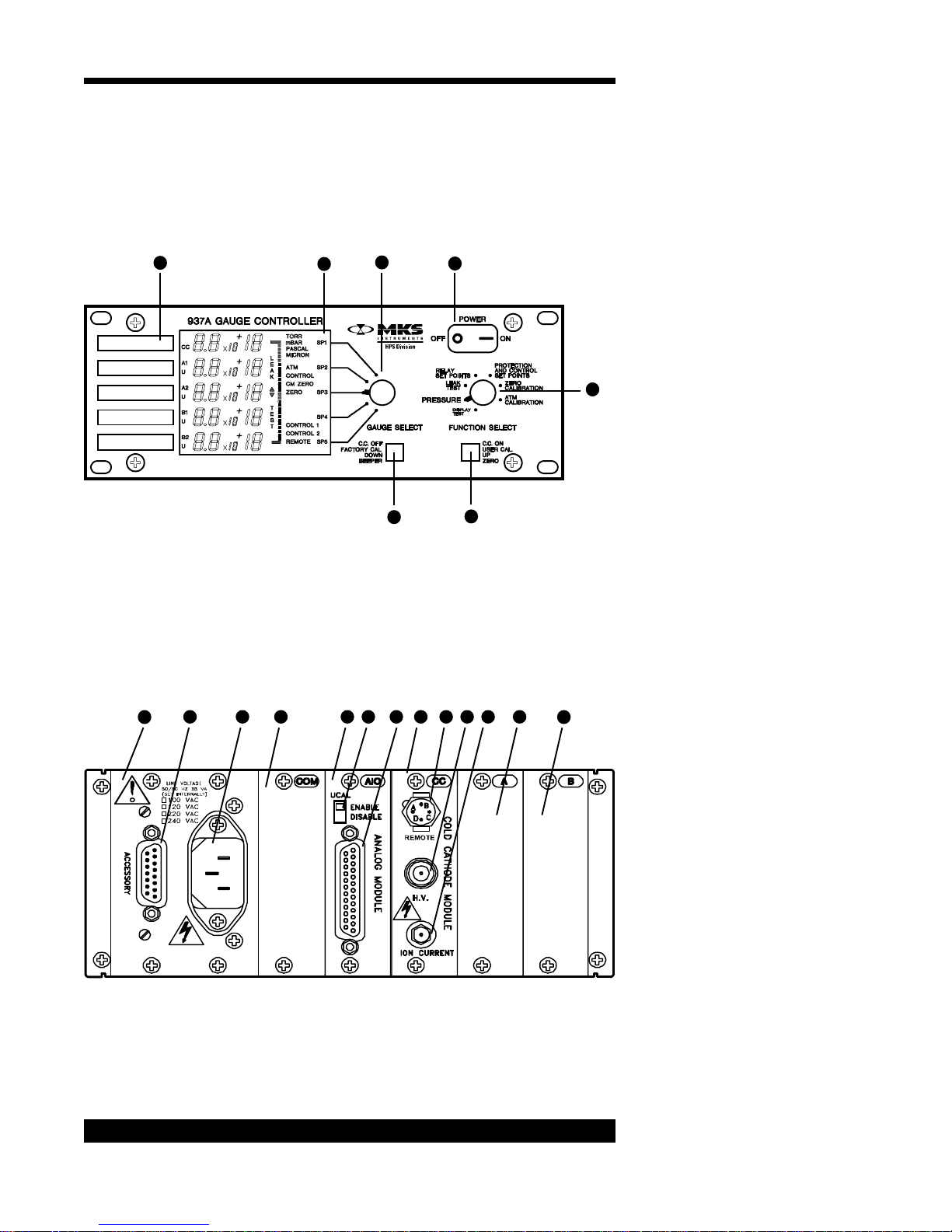
Feature and Control Locations
1
2
3
7
4
5
6
Front Panel
22
11
108 9
13 14 15 16 17 18 19
12
Rear Panel
937A Multi-Sensor System
20
 Loading...