

MKS HPS Service Manual
tm
HPS
Two-Stage Valve
Service Manual
651 Lowell Street
Methuen, MA 01844
Main Telephone: (800) 227-8766 p/n 1061054
www.mksinst.com
Rev. 001

Copyright © 2015 by MKS Instruments, Inc.
All rights reserved. No part of this work may be reproduced or transmitted in any form or by any means,
electronic or mechanical, including photocopying and recording, or by any information storage or retrieval
system, except as may be expressly permitted in writing by MKS Instruments, Inc.
Printed in the United States of America
DeviceNet™ is a trademark of Open DeviceNet Vendor Association, Inc., Coral Springs, FL.
®
SEMI
is a registered trademark of Semiconductor Equipment and Materials International, Mountain View,
CA.
®
Swagelok
and VCR® are registered trademark of Swagelok Marketing Co., Solon, OH.

Table of Contents
Valve Safety Information .................................................................................................................................. 1
Symbols Used in This Instruction Ma nual .................................................................................................................... 1
Symbols Found on the Unit ........................................................................................................................................... 1
Safety Procedures and Precautions ................................................................................................................................ 1
Sicherheitshinweise für das Ventil.................................................................................................................... 3
In dieser Betriebsanleitung vorkommende Symbole ..................................................................................................... 3
Erklärung der am Gerät angebrachten Symbole ............................................................................................................ 3
Sicherheitsvorschrift en und Vorsichtsmaßnahmen ....................................................................................................... 3
Informations de sécurité relatives au manomètre ........................................................................................... 5
Symboles utilisés dans ce manuel d’utilisation ............................................................................................................. 5
Symboles figurant sur l’unité ........................................................................................................................................ 5
Mesures de sécurité et précautions ................................................................................................................................ 5
Medidas de seguridad del manómetro ............................................................................................................. 7
Símbolos usados en este manual de instrucciones ......................................................................................................... 7
Símbolos hallados en la unidad ..................................................................................................................................... 7
Procedimientos y precauciones de seguridad ................................................................................................................ 7
How This Manual is Organized ..................................................................................................................................... 9
Customer Support .......................................................................................................................................................... 9
Chapter One: General Information .............................................................................................................. 10
Introduction ................................................................................................................................................................. 10
Chapter Two: Servicing an HPS Products Two-Stage Valve ..................................................................... 11
Disassembly of the main valve .................................................................................................................................... 11
Disassembly and Inspection of Internal Assembly ...................................................................................................... 12
Disassembly of the bypa ss valve ................................................................................................................................. 14
Disassembly and Inspection of the Bypass Valve ....................................................................................................... 15
Assembly of Main and Bypass Valves ........................................................................................................................ 15
List of Figures
No table of figures entries found.
List of Tables
Table 1: Definition of Symbols Found on the Unit............................................................................................. 1
Tabelle 2: Bedeutung der am Gerät angebrachten Symbole ............................................................................... 3
Tableau 3: Définition des symboles sur l’unité ................................
Tabla 4: Definición de los símbolos hallados en la unidad ................................................................................. 7
Table 5: Definitions .......................................................................................... Error! Bookmark not defined.
.................................................................. 5
iii

Valve Safety Information
The WARNING sign denotes a hazard. It calls attention to a procedure, practice,
condition, or
in injury to personnel.
The CAUTION sign denotes a hazard. It calls attention to an operating procedure,
practice, or the like, which, if not correctly performed or adhered to, could result in
damage to or destruction of all or part of the product.
The NOTE sign denotes important information. It calls attention to a procedure, practice,
condit
|
IEC 417, No. 5007
IEC 417, No. 5008
IEC 417, No. 5017
IEC 417, No. 5019
IEC 417, No. 5020
IEC 417, No. 5021
IEC 417, No. 5031
IEC 417, No. 5032
IEC 417, No. 5033-a
IEC 617-2, No. 020206
ISO 3864, No. B.3.1
ISO 3864, No. B.3.6
Valve Safety Information
Symbols Used in This Instruction Manual
Definitions of WARNING, CAUTION, and NOTE messages used throughout the manual are:
Warning
the like, which, if not correctly performed or adhered to, could result
Caution
Note
ion, or the like, which is essential to highlight.
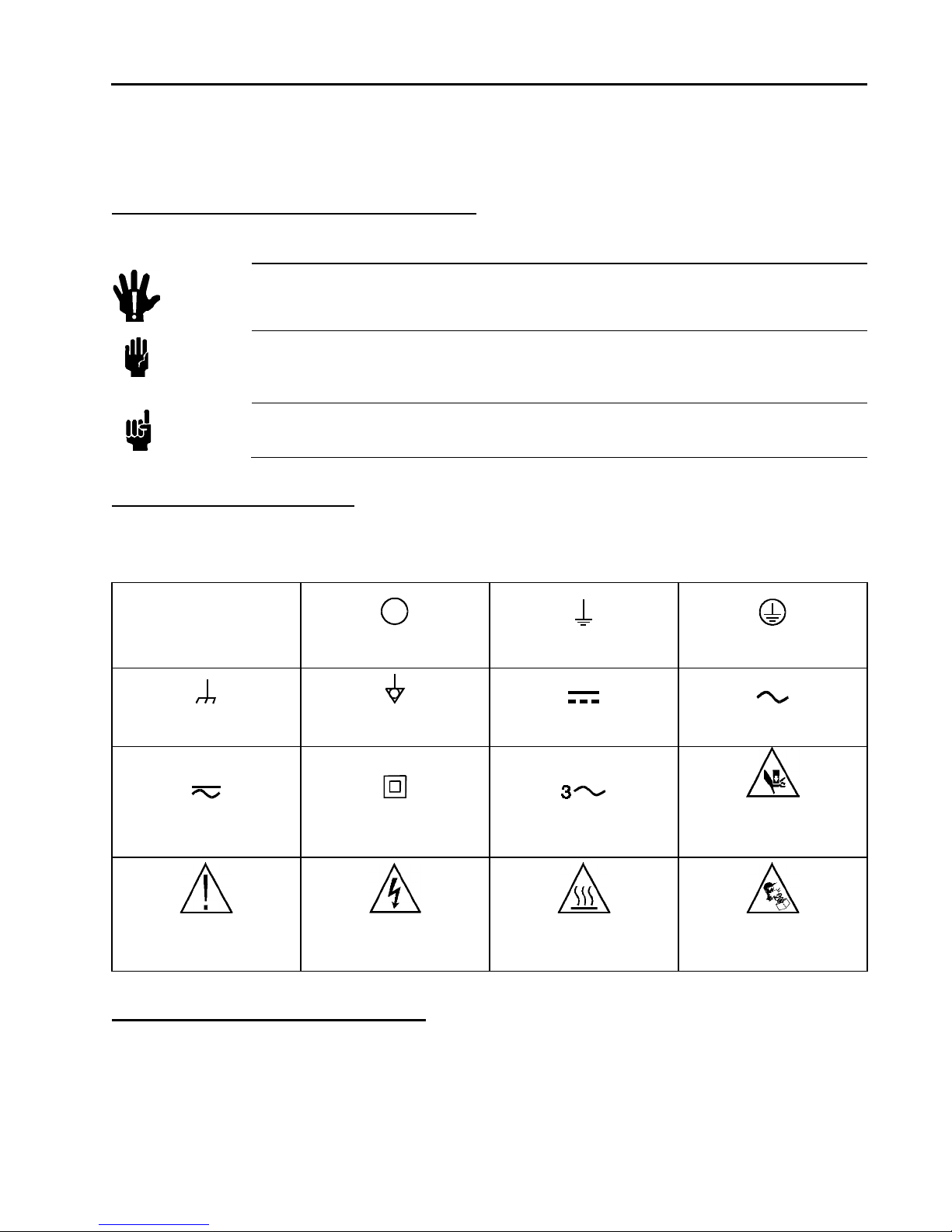
Symbols Found on the Unit
The following table describes symbols that may be found on the unit.
Table 1: Definition of Symbols Found on the Unit
On (Supply)
Frame or Chassis
Both Direct and Alternating
Current
Caution (refer to
accompanying documents)
Off (Supply)
Equipotentiality
Class II Equipment
IEC 417, No. 5172-a
Caution, Risk of Electric
Shock
Safety Procedures and Precautions
Earth (ground)
Direct Current
Three Phase
Alternating Current
Caution, Hot Surface
IEC 417, No. 5041
Protective Earth (ground)
Alternating Current
Caution, Hand Crush
ISO 3864
Caution, Spring Loaded
ISO 3864
Observe the following general safety precautions during all phases of operation of this instrument.
Failure to comply with these precaution s or with sp eci fic warnin gs else wh ere in this manu a l viola tes
safety standards of intended use of the instrument and may impair the protection provided by the
equipment. MKS Instruments, Inc. assumes no liability for the customer ’s fail ure to comp ly with thes e
requirements.
1

Valve Safety Information
Moving parts in the valve create a risk of personal injury until the valve is securely
incorporated into a system. To avoid injury, keep all body
valve opening.
1.
2.
Warning
parts away from any
Do not insert objects into openings where contact with moving parts is
possible.
Isolate the valve from any electrical or pneumatic power supply before
handling the valve.
DO NOT SUBSTITUTE PARTS OR MODIFY VALVE
Do not install substitute p arts or perform any unaut horized mod ification to the valve. Return the valve to an MK S
Calibration and Service Center for service and repair to ensure that all safety features are maintained.
SERVICE BY QUALIFIED PERSONNEL ONLY
Operating personnel must not attempt component replacement and internal adjustments. Qualified service personnel
must perform any service only.
USE CAUTION WHEN OPERATING WITH HAZARDOUS MATERIALS
If hazardous materials are used, observe the proper safety precautions, completely purge the valve when necessary, and
ensure that the material used is compatible with the wetted materials in this product, including any sealing materials.
PURGE THE VALVE
After installing the unit, or befor e removing it from a system, purge the unit completely with a clean, dry gas to eliminate
all traces of the previously used flow material.
USE PROPER PROCEDURES WHEN PURGING
This valve must be purged under a ventilation hood and gloves must be worn for protection.
DO NOT OPERATE IN AN EXPLOSIVE ENVIRONMENT
To avoid explosion, do not operate this product in an explosive environment unless it has been specifically certified for
such operation.
USE PROPER FITTINGS AND TIGHTENING PROCEDURES
All valve fittings must be consistent with valve specifications and compatible with the intended use of the valve.
Assemble and tighten fittings ac c ording to manufacturer’s directions.
CHECK FOR LEAK-TIGHT FITTINGS
Carefully check all vacuum component connections to ensure leak-tight installation.
OPERATE AT SAFE INLET PRESSURES
Never operate the valve at pressures higher than the rated maximum pressure (refer to the product specifications for the
maximum allowable pressure).
INSTALL A SUITABLE BURST DISC
When operating from a pressurized gas source, install a suitable burst disc in the vacuum system to pr e vent system
explosion should the sys t em pressure rise.
KEEP THE UNIT FREE OF CONTAMINANTS
Do not allow contaminants to enter the unit before or during use. Contamina tion such as dust, dirt, lint, glass chips, and
metal chips may permanently damage the unit or contaminate the process.
KEEP AWAY FROM VALVE OPENING
Keep fingers, other body parts, and other materials away from the valve opening when the valve is in operation.
2
Sicherheitshinweise für das Ventil
Das Symbol WARNUNG! weist auf eine Gefahr für das B
macht auf einen Arbeitsablauf, ei n e Arbeitsweise, einen Zustand oder eine
sonstige Gegebenheit aufmerksam, deren unsachgemäße Ausführung bzw.
ungenügende Berücksichtigung zu Verletzungen führen kann
Das Symbol VORSICHT! weist auf eine Gefahr für das Gerät hin. Es macht auf
einen Bedienungsablauf, eine Arbeitsweise oder eine sonstige Gegebenheit
aufmerksam, deren unsachgemäße Ausführung bzw. ungenügende
Berücksichtigung zu einer Besch
Teilen des Gerätes führen kann
Das Symbol HINWEIS macht auf wichtige Informationen bezüglich eines
Arbeitsablaufs, einer Arbeitsweise, eines Zustands oder einer so
aufmerksam.
|
IEC 417, No.5007
IEC 417, No.5008
IEC 417, No.5017
IEC 417, No.5019
IEC 417, No.5020
IEC 417, No.5021
IEC 417, No.5031
IEC 417, No.5032
IEC 417, No.5172-a
IEC 617-2, No.020206
ISO 3864
Sicherheitshinweise für das Ventil
In dieser Betriebsanleitung vorkommende Symbole
Bedeutung der mit WARNUNG!, VORSICHT! und HINWEIS gekennzeichneten Absätze in dieser
Betriebsanleitung.
Warnung!
Vorsicht!
edienpersonal hin. Es
.
ädigung oder Zerstörung des Gerätes oder von
.
Hinweis
nstige Gegebenheit
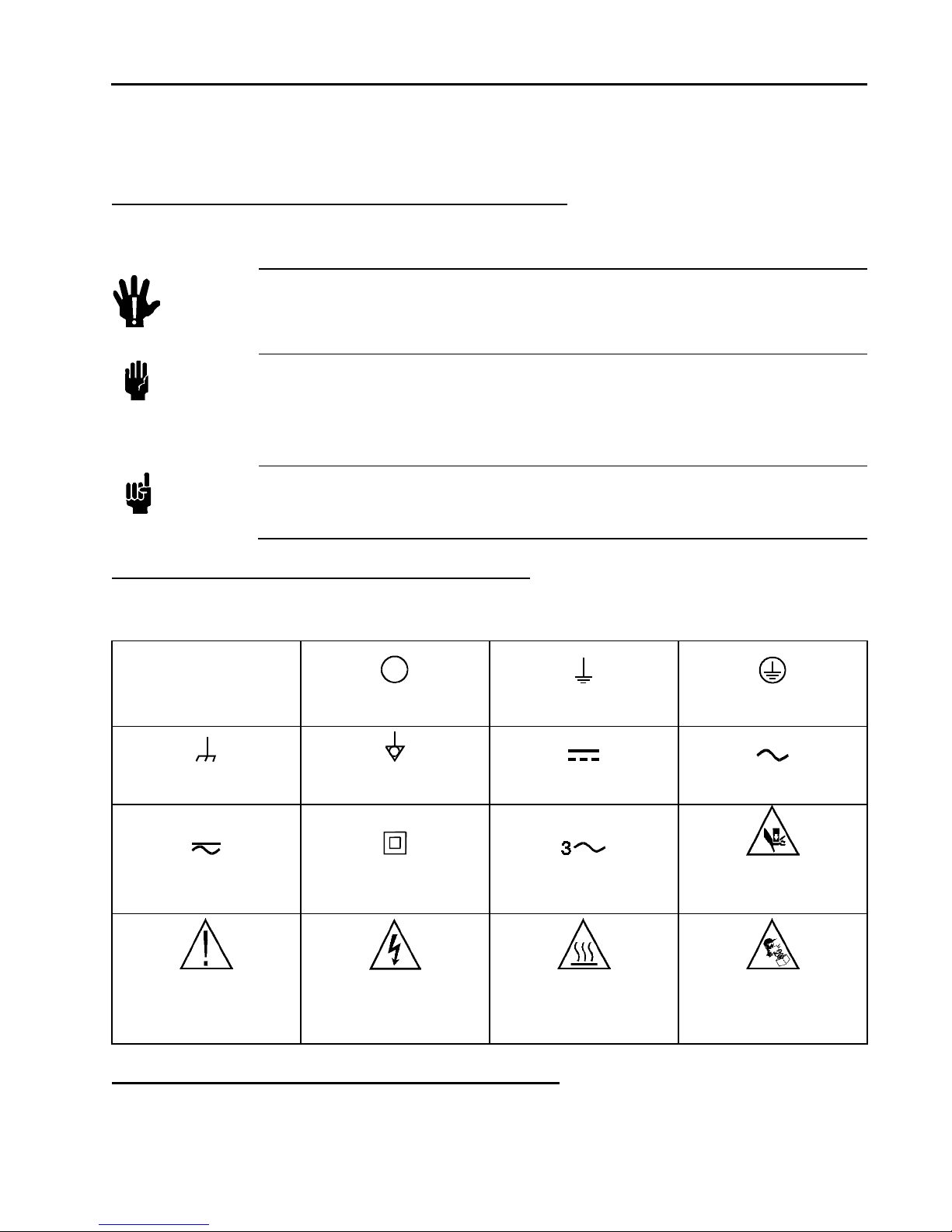
Erklärung der am Gerät angebrachten Symbole
Nachstehender Tabelle sind die Bedeutungen der Symbole zu entnehmen, die am Gerät angebracht sein können.
Tabelle 2: Bedeutung der am Gerät angebrachten Symbole
Ein (Energie)
Aus (Energie)
Erdanschluss
Schutzleiteranschluss
Masseanschluss
Gleich- oder Wechselstrom
IEC 417, No.5033-a
Warnung vor einer
Gefahrenstelle (Achtung,
Dokumentation beachten)
ISO 3864, No.B.3.1
Aquipotentialanschluss
Durchgängige doppelte
oder verstärkte Isolierung
Warnung vor gefährlicher
elektrischer Spannung
ISO 3864, No.B.3.6
Gleichstrom
Dreileiter-Wechselstrom
(Drehstrom)
Höhere Temperatur an
leicht zugänglichen Teilen
IEC 417, No.5041
Sicherheitsvorschriften und Vorsichtsmaßnahmen
Folgende allgemeine Sicherheitsvorschriften sind während allen Betriebsphasen dieses Gerätes zu
befolgen. Eine Missachtung der Sicherheitsvorschriften und sonstiger Warnhinweise in dieser
3
Wechselstrom
Vorsicht: Quetschgefahr für
die Hand
Vorsicht: Federspannung
ISO 3864
 Loading...