

MKS HPQ3, HPQ3S Maintance Manual

HPQ3 (S)
Hardware Manual
HPQ3 Hardware Manual – SP101019.101
October2012

2
As part of our continuous product improvement policy, we are always pleased to receive your comments
and suggestions about how we should develop our product range. We believe that the manual is an
important part of the product and would welcome your feedback, particularly relating to any omissions or
inaccuracies you may discover.
You can send your comments to:-
MKS Instruments UK Ltd - Spectra Products
Cowley Way
Weston Road
Crewe
Cheshire
CW1 6AG
U.K.
+44 (0)1270 250150 Tel. International
+44 (0)1270 251939 Fax. International
Email: manual_info@mksinst.com
MKS Products provided subject to the US Export Regulations.
Diversion or transfer contrary to U.S. law is prohibited.
HPQ3 is a registered trademark of MKS Instruments UK Limited.
Conflat® is a registered trademark of Varian Associates.
Viton® is a registered trademark of E.I. DuPont de Nemours & Co., Inc.
Windows® is a trademark of the Microsoft Corporation.
All other brand or product names are trademarks or registered trademarks of their respective companies and as such are fully
recognised.
MKS Instruments UK Ltd
HPQ3 Hardware Manual – SP101019.101 October 2012

3
Table of Contents
Overview 7
1. Specifications 9
1.1 Mechanical 9
HPQ3 9
24VDC Power Supply 9
Analyser 9
1.2 Electrical 10
Power Supply 11
1.3 Environmental 11
Temperature range 11
1.4 Safety 11
1.5 Connectors 11
1.6 Warning labels 12
1.7 Ventilation 12
2. Rear Panel Connections 17
2.1 X-Trip 18
2.2 Audio Socket 18
2.3 Emission Indicator 19
2.4 Multiplier Indicator – N/A 19
2.5 Power Indicator 19
2.6 Gauge Connector 20
2.7 Power 20
2.8 Analogue I/O Connector 21
3. Analyser Installation 25
3.1 Unpacking 25
3.2 Inspecting the analyser 25
3.3 Installing the analyser 27
3.4 Checking the system pressure 27
3.5 Mounting the analyser 29
4. HPQ3 Installation 30
4.1 Installation 30
4.2 Electrical connections 30
5. Connecting to the Ethernet Port 32
5.1 Adding the HPQ3 33
5.2 Directly connecting to the HPQ3 35
5.3 Assigning a static IP Address 39
6. Baking 42
7. Analyser Maintenance 43
7.1 Overview 43
7.2 Ohmmeter analyser checks 44
7.3 Checking filaments 45
7.4.1 Removing the filaments 47
7.4.2 Fitting filaments 51
51
7.5 Ion Source cleaning 52
7.5.1 Cleaning while fitted to the analyser
52
2.9 Digital I/O Connector 22
2.10 Ethernet 24
MKS Instruments UK Ltd
HPQ3 Hardware Manual – SP101019.101 October 2012
7.5.2 Removing the ion-source to clean or
replace 53

4
8. Exploded Views 56
Complete Ion-source 58
Analyser pin-outs 56
9. Spare Parts 58
Filaments 58
10. Returning Your Unit for Service 59
Support Contact Numbers 59
MKS Instruments UK Ltd
HPQ3 Hardware Manual – SP101019.101 October 2012

5
2004/108/EEC Electromagnetic Compatibility Directive
EN 61326-1:2006 Electrical equipment for measurement, control & laboratory use.
2006/95/EC Low Voltage Directive
EN 61010-1:2006 Safety requirements for electrical equipment for measurement, control &
laboratory use.
MKS Instruments UK Ltd
3 – 4 Cowley Way
Crewe
Cheshire
CW16AG
United Kingdom
EC Declaration of Conformity
MKS Instruments UK Ltd declares that the:
HPQ3 RGA (MKS114) control electronics package
Is in accordance with the following directives:
I hereby declare that the equipment named above has been designed to comply with the relevant
sections of the above referenced specifications. The unit complies with all essential requirements
of the Directives.
MKS Instruments UK Ltd
HPQ3 Hardware Manual – SP101019.101 October 2012

6
Signed:
J.M.Higgins
General Manager
10th October 2009
MKS Instruments UK Ltd
HPQ3 Hardware Manual – SP101019.101 October 2012

7
Overview
The HPQ3 is the latest innovation in RGA technology from MKS Instruments allowing operation far
beyond the 1e-4mbar of conventional RGA’s without the need for differential pumping.
The field proven analyser technology of the HPQ analyser coupled with the latest innovative
electronics technology derived from the Microvision2 family give data quality not previously seen in
this class of instrument. The resulting system is less complex, with reduced installation
requirements, offering a higher level of reliability at a substantially lower cost.
In addition, the HPQ3S uses application validated correction algorithms to compensate for the
sensitivity variation arising from ion-molecule interactions in the ion source at higher pressures.
This allows reliable data to be obtained for specific gas species including water, oxygen, nitrogen,
methane, helium and hydrogen in argon and other gas mixtures.
Features
Data acquisition through solid state, wide dynamic range, fast settling detector electronics.
Temperature stabilized critical components offering improved signal stability and drift.
Calibrations and configurations stored locally within the RGA.
Flexible I/O capability including a dedicated gauge port.
Further expandability of the I/O capabilities using add-in cards.
TCP/IP and ASCII protocol support
Operation
The HPQ3 is designed to be operated in several ways:
From a host computer – an IBM compatible PC or MAC running the MKS Process Eye
Professional or EasyView software package.
PC or MAC using a web browser such as Internet Explorer or Safari.
Integration into existing systems controlling through the use of the ASCII protocol command set.
MKS Instruments UK Ltd
HPQ3 Hardware Manual – SP101019.101 October 2012

8
This manual focuses on HPQ3 hardware and should be used in conjunction with the relevant user
interface manual during installation.
Any required network communications cards should be installed and configured prior to installing
the HPQ3, or RGA software if supplied.
MKS Instruments UK Ltd
HPQ3 Hardware Manual – SP101019.101 October 2012

9
1. Specifications
1.1 Mechanical
HPQ3
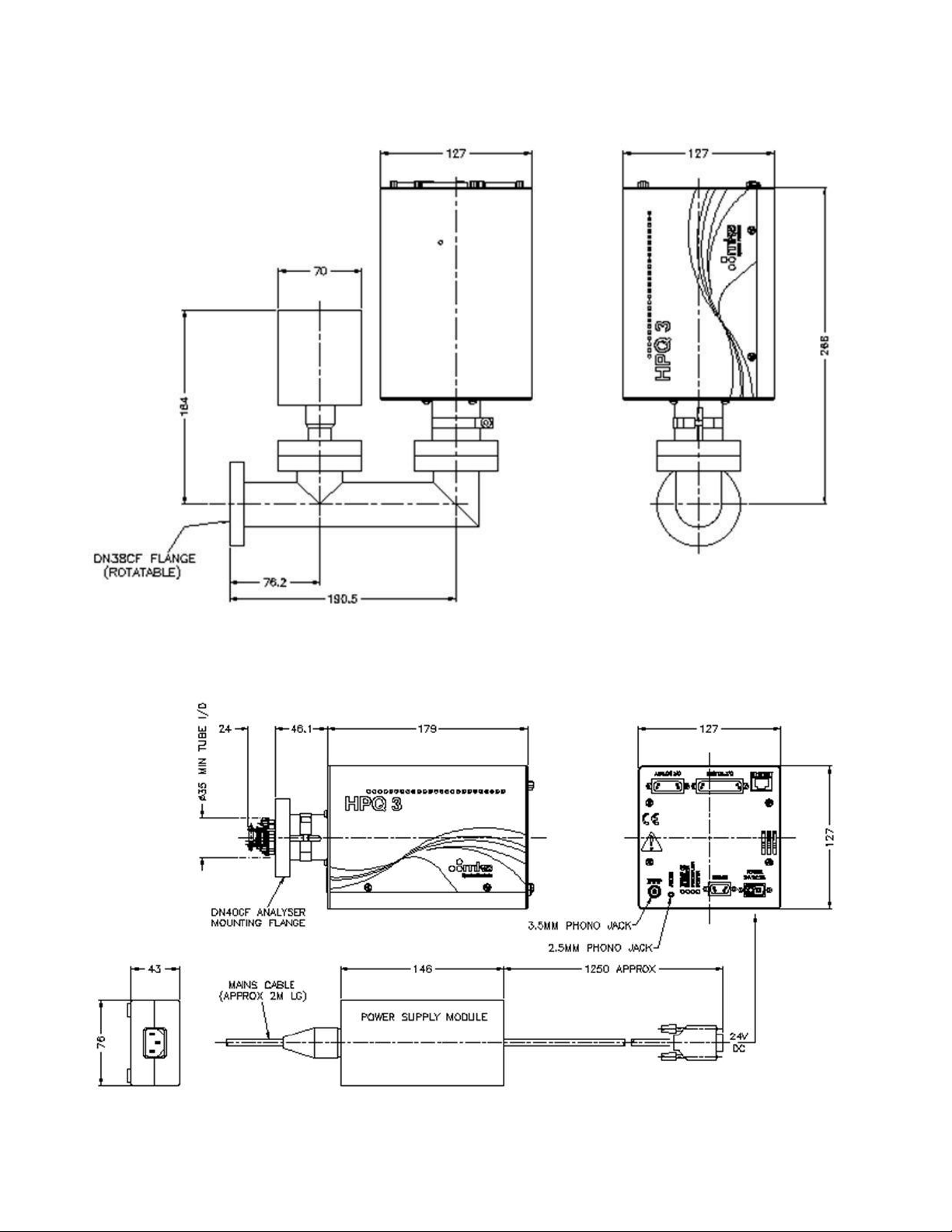
Dimensions:
127mm wide x 127mm x 179mm deep, plus 46mm over analyser connector to face of CF flange.
Weight:
1.7 kg
24VDC Power Supply
Dimensions:
75mm wide x 45mm high x 146mm deep plus 30mm over strain relief.
Weight:
0.6 kg
Analyser
Max. Operating pressure
HPQ3 1e-3 Torr (1.3e-3 mbar)
Maximum transient burst pressure
4e-2 Torr (5e-2 mbar) – gas dependant
HPQ3S 8e-3 Torr (1e-2 mbar) – Application
dependant
MKS Instruments UK Ltd
HPQ3 Hardware Manual – SP101019.101 October 2012
10
MKS Instruments UK Ltd
HPQ3 Hardware Manual – SP101019.101 October 2012

11
1.2 Electrical
Power Supply
100 to 120, 200 to 240 VAC rms 47- 63Hz @ 2.1A rms
Installation category (over voltage category) II to IEC664
Fuses Internal, not user replaceable
Insulation Class I to IEC536
1.3 Environmental
Temperature range
0 to 400C, 80%RH non-condensing, operating and storage
Pollution degree 2 to EN61010
Enclosure IP20 to EN60529
1.4 Safety
IP20 to EN60529
The protective earth conductor of the power cord must be connected to the power source
protective earth terminal.
There are no operator replaceable parts within the 24VDC power supply unit or the HPQ3 unit.
1.5 Connectors
The connectors for external circuits are for use only with MKS equipment, or equipment which has
no accessible hazardous live parts.
The external circuits must comply with the requirements of EN61010-1 section 6.6.1.
Ports for connection of accessories do not carry hazardous potentials.
Do not position the 24VDC power supply so that it is difficult to unplug the supply power cord.
Installation Category II comprises mains powered, local level appliances.
MKS Instruments UK Ltd
HPQ3 Hardware Manual – SP101019.101 October 2012
12
1.6 Warning labels
Refer to:
a. Accessible hazardous voltages on analyser connector, when not mated to the analyser, which
may result in a non-hazardous electric stock if touched.
b. Tuning adjustment holes, which are not for operator use.
On the rear panel refers to:
a. Read all instructions carefully before use.
b. The control unit and signal ports are designed for connection to MKS accessories via MKS
supplied cables.
There are no accessible hazardous voltages or currents on these ports.
MKS must be consulted before any non-MKS supplied cables or accessories are connected to
these ports.
1.7 Ventilation
The openings in the sides and rear panels must not be obstructed.
MKS Instruments UK Ltd
HPQ3 Hardware Manual – SP101019.101 October 2012

13
Allow a minimum clearance of 50mm all round.
Do not exceed the maximum operating ambient temperature.
MKS Instruments UK Ltd
HPQ3 Hardware Manual – SP101019.101 October 2012

14
Additional Installation Maintenance and Operating Instructions
In order to comply with European regulations, the following procedures must be followed:
A) INSTALLATION
1. The installation procedures given in the operating and technical manuals must be followed in
addition to these instructions.
2. The mains power cable must conform to local regulations and must have a protective earth (PE)
conductor securely connected to the power plug protective earth contact.
3. The short earthing braid supplied with some products, must be fitted between the terminal on the
RF head and one of the CF40 vacuum flange bolts.
4. Only cables supplied with the equipment may be used for interconnections. If extension cables
are required to obtain a greater separation between control unit and RF head, or if longer serial
communications cables are required, they must be supplied by MKS Instruments Ltd.
5. Cables attached to all other ancillary signal and control ports must have a length of less than 3
meters. If greater length is required, MKS Instruments Ltd. must be contacted for technical
guidance on possible EMC and safety issues.
6. The vacuum system on which the analyser/RF head is mounted must be earthed, to a protective
earth, preferably to the same protective earth as the control unit.
B) OPERATION
1. The equipment is not authorised for use as a critical component in a life support or safety critical
system without the express written approval of MKS Instruments Ltd.
2. All instructions given in the operating manual must be followed.
3. Adjustments are strictly limited to those accessible from the control panel and computer
keyboard and only when running software supplied by MKS Instruments Ltd.
MKS Instruments UK Ltd
HPQ3 Hardware Manual – SP101019.101 October 2012

15
MKS Instruments UK Ltd
HPQ3 Hardware Manual – SP101019.101 October 2012

16
C) MAINTENANCE
WARNING-DANGEROUS VOLTAGES EXIST INSIDE
THE EQUIPMENT
1. Maintenance functions must only be carried out by competent persons.
2. During the warranty period, faulty equipment must be returned to MKS Instruments, Spectra
Products Ltd., unless special arrangements are made.
3. There are no user serviceable parts in the electronic equipment. Certain components are EMC
and safety critical and must not be substituted. Replacement parts are available from MKS
Instruments UK Ltd.
4. Equipment enclosures embody certain special fastenings and bonding devices that affect EMC
and safety performance. These must be correctly re-fitted after servicing.
MKS Instruments UK Ltd
HPQ3 Hardware Manual – SP101019.101 October 2012
17
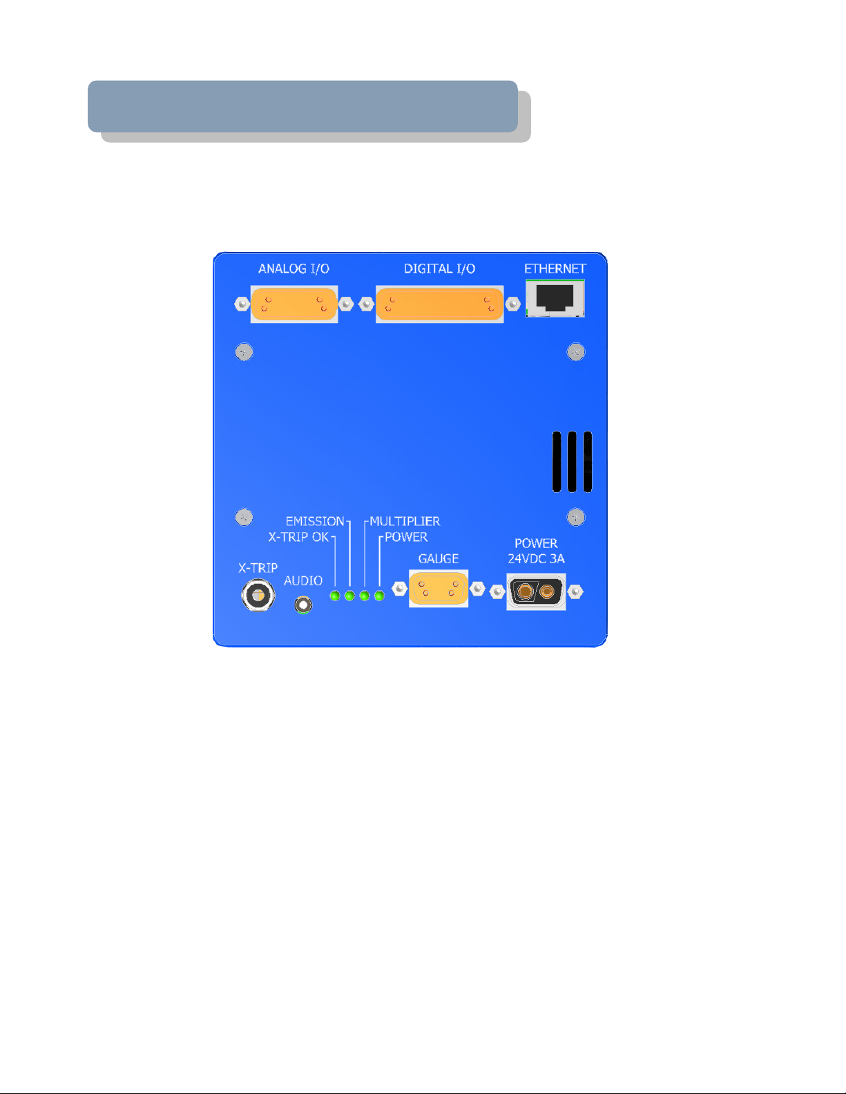
2. Rear Panel Connections
The rear panel incorporates all the connections required by the HPQ3 RGA.
Details on these connectors and their use can be found in this section.
MKS Instruments UK Ltd
HPQ3 Hardware Manual – SP101019.101 October 2012

18
2.1 X-Trip
The X-Trip connector requires a special locking, stereo jack plug, which is supplied with the unit.
Do not use a standard 3.5mm jack plug. Replacements are available from MKS Instruments if
required.
The external trip feature is used to protect the filaments and electron multiplier from exposure to
high pressures. It allows an independent total pressure gauge or signal from a vacuum control
system to be connected to the HPQ3 as protection against accidental damage.
It is the most effective of the trips available and we would always recommend its use.
The external trip input can be driven in three ways:
1. Uncommitted relay contact
This is a low voltage (+5V, 1mA) contact. The contact should be closed for normal operation, open
to trip the filaments, or if the protective equipment is switched off.
2. Open collector TTL drive
The output transistor should be on for normal operation, off for trip, or if the protective equipment is
turned off.
3. Totem pole TTL drive
The signal should be low for normal operation, high for a trip condition, or if the protective
equipment is switched off.
The external trip circuitry is galvanically isolated from the system ground. The maximum common
mode voltage is 60V DC or peak AC, current limited to 2mA.
2.2 Audio Socket
This is a 2.5mm jack socket. It is used to connect headphones or an external amplified speaker so
that audio tones generated in some of the modes can be heard. E.g. Leak checking tone and audio
alarms.
The minimum load impedance should be 8 ohms and the power handling is 2 watts max.
MKS Instruments UK Ltd
HPQ3 Hardware Manual – SP101019.101 October 2012

19
2.3 Emission Indicator
The indicator is lit when a filament is active and within correct operating parameters.
2.4 Multiplier Indicator – N/A
2.5 Power Indicator
The indicator is lit when power is supplied to the HPQ3 unit.
MKS Instruments UK Ltd
HPQ3 Hardware Manual – SP101019.101 October 2012

20
2.6 Gauge Connector
Pin
Function
Description
1
Gauge On
Open collector output from gauge
2
No connection
3 24VDC Output
24VDC supply output, fused at 120mA
4
0V Ground
5
Differential Signal Input High
Gauge pressure output
6
0V Ground
7
No connection
8 Differential Signal Input Low
Gauge pressure output
9
Gauge Enable
Open collector to gauge
Pin
Function
Description
1
24VDC
A2
0V
A standard 9-way D-type socket used to interface to a total pressure gauge. This may be already in
use depending on the type of RGA system purchased.
2.7 Power
A 2-pin D-type connecter used to for the 24VDC power supply.
MKS Instruments UK Ltd
HPQ3 Hardware Manual – SP101019.101 October 2012
 Loading...