

MKS HPQ2-IP User Manual

HPQ2-IP
Manual
SP101009.103
10 October 2012

HPQ2-IP SP101009.102 – 10 October 2012
MKS Instruments, Spectra Products
2
As part of our continuous product improvement policy, we are always pleased to
receive your comments and suggestions about how we should develop our product
range. We believe that the manual is an important part of the product and would
welcome your feedback particularly relating to any omissions or inaccuracies you
may discover.
You can send your comments to:-
MKS Instruments, Spectra Products
Cowley Way
Weston Road
Crewe, Cheshire
CW1 6AG
United Kingdom
Tel: +44 (0) 1270 250150
Email: Maual_info@mksinst.com
MKS Products provided subject to the US Export Regulations. Diversion or
transfer contrary to U.S. law is prohibited.
Windows and Windows95 are trademarks of the Microsoft Corporation and as such are fully
recognised.
Conflat is a registered trademark of Varian Associates.
Viton is a registered trademark of E.I. Dupont de Nemours & Co., Inc.
All other brand or product names are trademarks or registered trademarks of their respective
companies.

HPQ2-IP SP101009.102 – 10 October 2012
MKS Instruments, Spectra Products
3
Declaration of Conformity
Spectra SensorTech Ltd.
Cowley Way
Crewe
Cheshire
CW1 6AG
United Kingdom
DECLARES THAT THE FOLLOWING PRODUCT:
LM101 HPQ2-IP Control unit
IS IN CONFORMITY WITH THE FOLLOWING EUROPEAN DIRECTIVES:
2004/108/EEC ELECTROMAGNETIC COMPATIBILITY DIRECTIVE
2006/95/EC LOW VOLTAGE DIRECTIVE
THE APPLICABLE STANDARDS ARE:
EN 61326:1998 ELECTRICAL EQUIPMENT FOR MEASUREMENT, CONTROL &
LABORATORY USE.
EN 61010-1:1993 SAFETY REQUIREMENTS FOR ELECTRICAL
EQUIPMENT FOR MEASUREMENT, CONTROL
& LABORATORY USE.
WARNING
This apparatus shall not be used in the residential, commercial, and light
industrial environment unless further mitigation measures are taken.
For advice please contact Spectra SensorTech Ltd.
SIGNED:
J.M.Higgins
GENERAL MANAGER
DATE: 19
th
February 2007
HPQ2-IP SP101009.102 – 10 October 2012
MKS Instruments, Spectra Products
4
Safety
IP20 to EN60529
The protective earth conductor of the power cord must be connected to the power
source protective earth terminal.
There are no operator replaceable parts within the 24VDC power supply unit or the
HPQ2 unit.
Connectors
The connectors for external circuits are for use only with MKS Spectra equipment, or
equipment which has no accessible hazardous live parts.
The external circuits must comply with the requirements of EN61010-1 section
6.6.1.
Ports for connection of accessories do not carry hazardous potentials.
Do not position the 24VDC power supply so that it is difficult to unplug the supply
power cord.
Installation Category II comprises mains powered, local level appliances.
Warning labels
On the front panel refers to:
a. Accessible hazardous voltages on analyser connector, when not mated to the
analyser, which may result in a non-hazardous electric stock if touched.
b. Tuning adjustment holes, which are not for operator use.

HPQ2-IP SP101009.102 – 10 October 2012
MKS Instruments, Spectra Products
5
On the rear panel refers to:
a. Read all instructions carefully before use.
b. The control unit and signal ports are designed for connection to MKS Spectra
accessories via MKS Spectra supplied cables.
There are no accessible hazardous voltages or currents on these ports.
MKS Spectra must be consulted before any non-MKS Spectra supplied cables or
accessories are connected to these ports.
Ventilation
Openings in the front, top and bottom panels must not be obstructed.
Allow a minimum clearance of 50mm all round. Do not exceed the maximum
operating ambient temperature.

HPQ2-IP SP101009.102 – 10 October 2012
MKS Instruments, Spectra Products
6
Additional Installation Maintenance and Operating Instructions
In order to comply with European regulations, the following procedures must be
followed:
A) INSTALLATION
1. The installation procedures given in the operating and technical manuals must be
followed in addition to these instructions.
2. The mains power cable must conform to local regulations and must have a
protective earth (PE) conductor securely connected to the power plug protective
earth contact.
3. The short earthing braid supplied with some products, must be fitted between
the terminal on the RF head and one of the CF40 vacuum flange bolts.
4. Only cables supplied with the equipment may be used for interconnections. If
extension cables are required to obtain a greater separation between control unit
and RF head, or if longer serial communications cables are required, they must be
supplied by MKS Instruments Ltd.
5. Cables attached to all other ancillary signal and control ports must have a length
of less than 3 metres. If greater length is required, MKS Instruments Ltd. must be
contacted for technical guidance on possible EMC and safety issues.
6. The vacuum system on which the analyser/RF head is mounted must be earthed,
to a protective earth, preferably to the same protective earth as the control unit.
B) OPERATION
1. The equipment is not authorised for use as a critical component in a life support
or safety critical system without the express written approval of MKS Instruments
Ltd.
2. All instructions given in the operating manual must be followed.
3. Adjustments are strictly limited to those accessible from the control panel and
computer keyboard and only when running software supplied by MKS Instruments
Ltd.

HPQ2-IP SP101009.102 – 10 October 2012
MKS Instruments, Spectra Products
7
C) MAINTENANCE
WARNING-DANGEROUS VOLTAGES EXIST INSIDE THE EQUIPMENT
1. Maintenance functions must only be carried out by competent persons.
2. During the warranty period, faulty equipment must be returned to MKS
Instruments, Spectra Products Ltd., unless special arrangements are made.
3. There are no user serviceable parts in the electronic equipment. Certain
components are EMC and safety critical and must not be substituted. Replacement
parts are available from MKS Instruments, Spectra Products Ltd.
4. Equipment enclosures embody certain special fastenings and bonding devices
that affect EMC and safety performance. These must be correctly re-fitted after
servicing.

HPQ2-IP SP101009.102 – 10 October 2012
MKS Instruments, Spectra Products
8
Safety ........................................................................................................ 4
Connectors ............................................................................................... 4
Warning labels.......................................................................................... 4
Ventilation................................................................................................ 5
1. Specification ....................................................................................... 10
2. Introducing HPQ2-IP ......................................................................... 12
3. Control Unit Overview ........................................................................ 13
3.1 The Rear Panel ................................................................................. 14
3.2 Power Connector ........................................................................... 14
3.3 Indicators ..................................................................................... 15
3.4 Ethernet Connector ........................................................................ 15
3.5 Audio Output ................................................................................. 16
3.6 Analog I/O Connector..................................................................... 16
3.7 Digital I/O Connector ..................................................................... 17
3.8 Reset Switch ................................................................................. 18
3.9 External Trip ................................................................................. 18
4. Analyser Installation .......................................................................... 19
4.1 Unpacking ........................................................................................ 19
4.2 Inspecting the Analyser ..................................................................... 19
4.3 Installing the Analyser ....................................................................... 20
4.4 Checking the System Pressure ............................................................ 20
4.5 Mounting the Analyser ....................................................................... 20
5. Control Unit Installation .................................................................... 22
5.1 Connecting the Control Unit to the Analyser ......................................... 22
5.2 Electrical Connections ........................................................................ 23
5.3 IP Address ........................................................................................ 23
5.4 Re-setting the IP address ................................................................... 23
6. Baking ................................................................................................ 24
7. Analyser Maintenance ........................................................................ 25
7.1 General Overview .............................................................................. 25
7.2 Maintenance of Your Analyser ............................................................ 26
7.3 Failed Filaments ................................................................................ 27
7.4 Ohmmeter Analyser Checks ................................................................ 28
7.5 Checking for shorts ........................................................................ 28
7.6 Checking Filaments ........................................................................ 29
7.7 Changing Filaments........................................................................ 29
7.9 Fitting New Filaments ..................................................................... 31
7.10 Ion source, replacing and cleaning .................................................... 32
7.11 Removing the Ion Source ............................................................. 32
7.12 Cleaning the Source ..................................................................... 33
7.13 Re-fitting the Ion Source .............................................................. 34
8. Exploded Views .................................................................................. 35
8.1 Analyser Flange pin-outs .................................................................... 35
8.2 Exploded View of the Analyser ............................................................ 36

HPQ2-IP SP101009.102 – 10 October 2012
MKS Instruments, Spectra Products
9
9. Ion Source Parameters ...................................................................... 38
10. Communications Troubleshooting ................................................... 39
11. Returning Your Unit for Service ....................................................... 46

HPQ2-IP SP101009.102 – 10 October 2012
MKS Instruments, Spectra Products
10
1. Specification
General
Mass Range Capability
2 to 80 amu
Detector System
Faraday Cup
Maximum Recommended
Operating Pressure
1 x 10⁻² mBar
(8 x 10⁻³ Torr)
Maximum Permissible
Operating Pressure
2 x 10⁻² mBar
(1.6 x 10⁻² Torr)
Minimum Detectable Partial
Pressure
1 x 10
-10
mBar
(8 x 10
-11
Torr)
Mass Stability
Better than 0.1 amu over 8
hours at constant ambient
temperature
Resolution
<1.2 amu at 10% peak height
Total shipping weight
6.0kg
Analyser
Maximum Bakeout
Temperature
2500C
Mounting Flange
2 ¾ inch Conflat (CF35)
Insertion Length
1.0 inch (25.4mm)
Ion Source Sensitivity
5 x 10⁻⁵ A/Torr
Electron Energy
40 and 70 eV nominal
(adjustable from PC)
Emission Current
0.1 and 0.7mA nominal
(adjustable from PC)
Filaments
2, independent, tungsten

HPQ2-IP SP101009.102 – 10 October 2012
MKS Instruments, Spectra Products
11
Control unit
Control Unit Weight
2.3kg
Dimensions
127mm x 127mm x 210mm
Overall length
2245mm
Maximum Ambient
Operating Pressure
350C non-condensing
PC Software
Process Eye Professional or
Easyview
Power
24V DC 3A External supply
included
Communication
Ethernet
Distance
100Metres

HPQ2-IP SP101009.102 – 10 October 2012
MKS Instruments, Spectra Products
12
2. Introducing HPQ2-IP
The HPQ2-IP is a complete quadrupole residual gas analyser (RGA) designed to
operate at higher pressures than traditional quadrupole instruments. The HPQ2-IP
system is based around an extremely compact quadrupole analyser which has an
insertion length into the vacuum of 1 inch (25.4mm) and mounts on a CF35 (2 ¾
inch) Conflat flange.
The HPQ2-IP incorporates all of the electronics normally found in a separate control
unit and RF power supply into one extremely compact unit, which fits directly onto
the quadrupole analyser. A separate low voltage power supply connects to the
HPQ2-IP control unit.
The HPQ2-IP is designed to be operated from an IBM compatible PC running either
Process Eye Professional or Easyview software. Communication between the PC and
the HPQ2-IP is via an Ethernet link.
The complete HPQ2-IP system will comprise; HPQ2-IP analyser, HPQ2-IP control
unit, low voltage power supply, interconnecting cables, manual, tool kit and either
Process Eye Professional or Easyview software.
This manual focuses on the HPQ2-IP hardware and should be used in conjunction
with the manual for the operating software, Process Eye Professional or Easyview.

HPQ2-IP SP101009.102 – 10 October 2012
MKS Instruments, Spectra Products
13
3. Control Unit Overview
The HPQ2-IP control unit is a single unit incorporating all the necessary power
supply and data acquisition electronics for the residual gas analyser.
Power is derived from a dedicated low voltage power supply which is supplied as
part of the standard package.
Alternatively, power may be derived from a suitable Spectra Remote Vacuum
Controller if the complete system incorporates one.
The HPQ2-IP control unit plugs directly onto the HPQ2-IP quadrupole analyser via
the connector mounted on the front panel of the unit. All external connections
including the power supply and communications are made via connectors mounted
on the rear panel of the control unit.
The HPQ2-IP control unit contains no user serviceable parts and the only manual
adjustment is the volume control for the audio, which is mounted on the rear panel.
HPQ2-IP SP101009.102 – 10 October 2012
MKS Instruments, Spectra Products
14
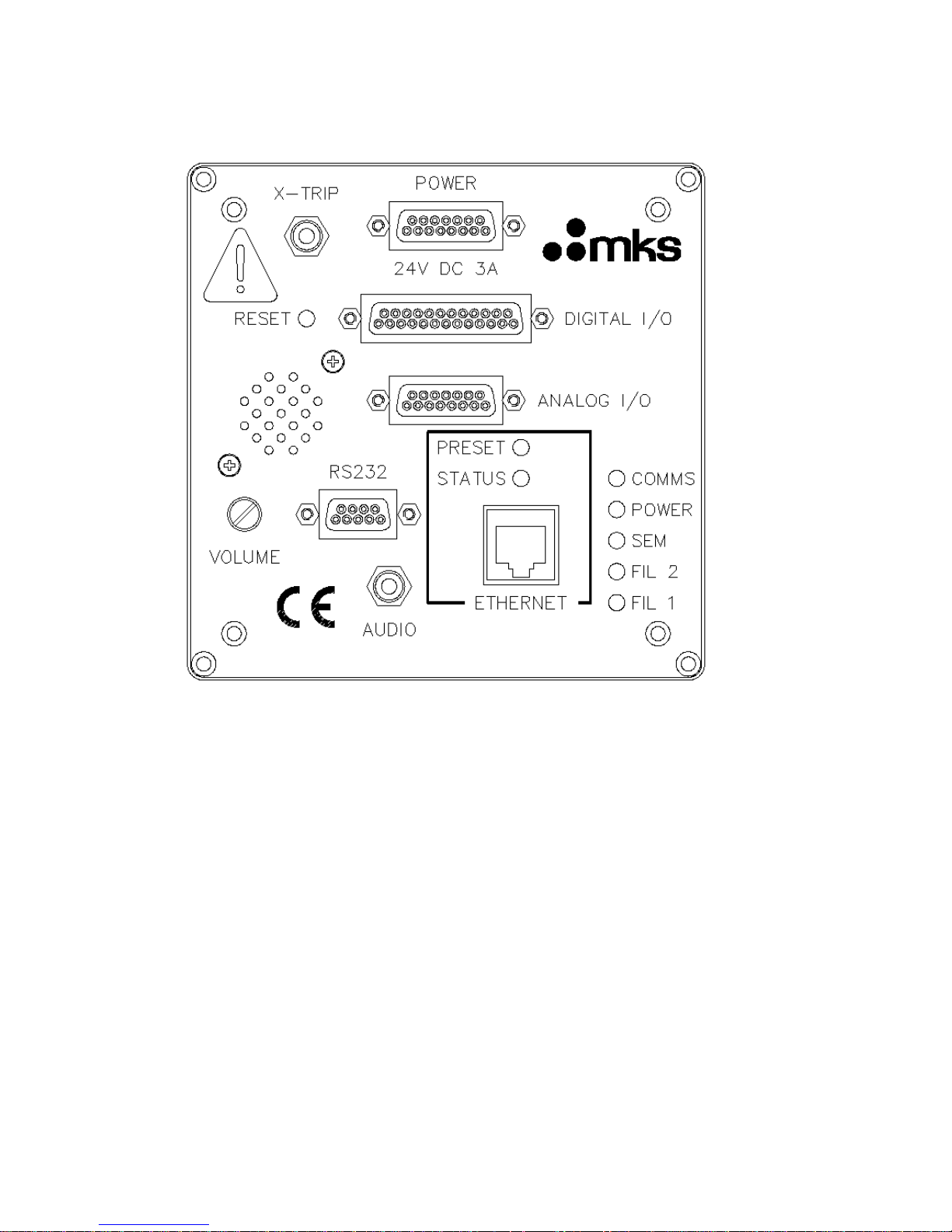
3.1 The Rear Panel
3.2 Power Connector
This is a 15 way D-Type socket labelled POWER on the rear panel of the unit to
connect to the low voltage power supply unit.
Pin connections are:-
1, 2, 3 (joined together) +24 volts DC
9, 10, 11 (joined together) 0 volts (24 volt return)
The power input is 24 volts DC 10%, 3 Amps max.
The current drawn depends on the mass range and whether a filament is on or off.

HPQ2-IP SP101009.102 – 10 October 2012
MKS Instruments, Spectra Products
15
3.3 Indicators
On the rear panel of the HPQ2-IP control unit there are six LED indicators, their
functions are described below.
Filament Indicators
An indicator, Fil1 or Fil2 is lit to show the currently active filament.
SEM Indicator
The indicator is lit when the SEM detector is active. This is not implemented on the
HPQ2-IP as there is no SEM detector fitted.
Power
The indicator is lit when power is supplied to the HPQ2 unit.
Comms
This indicator will flash to show a comms event to the HPQ2-IP unit. If there are no
active communications with the HPQ2-IP, this indicator will pulse at approximately
2Hz, depending on the RGA software version used.
Status
Indicates the current state of the instrument. The indicator is lit while the unit is
booting, or when in FTP mode, otherwise it is off.
3.4 Ethernet Connector
This is an RJ45 style connector used to connect the HPQ2-IP to the host computer.
Use standard Cat5 patch cables, as follows:
If connecting directly to a PC, use a “crossover” or “cross-wired” Cat5 Patch cable.
If connecting to a network, use a standard Cat5 Patch cable.
 Loading...