

MKS GV 210 Operating Instructions Manual
control – motion – interface
mks Maschinen-Kontroll-Systeme GmbH
Zwischen den Wegen 32
D-78239 Rielasingen - Germany
Tel. +49 (0)7731-9332-0
Fax +49 (0)7731-9332-30
info@mks-control.com
www.mks-control.com
GV21001e_e_A5.doc / Jul-07 Page 1 / 11
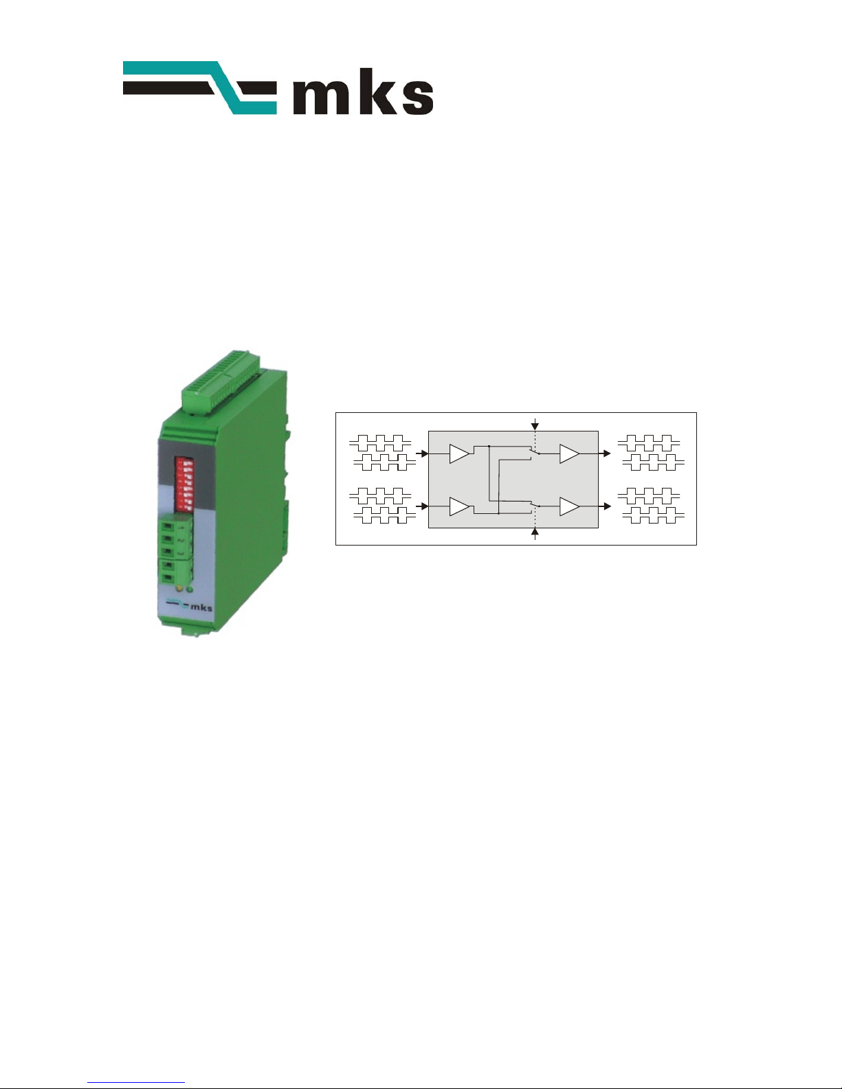
GV 210
Cross Switcher and Splitter
for Incremental Encoder Signals
In1
Control 1
Control 2
In2
Out1
Out2
A, /A, B, /B, Z, /Z
A, /A, B, /B, Z, /Z
A, /A, B, /B, Z, /Z
A, /A, B, /B, Z, /Z
• Universal encoder interface, applicable as level converter, encoder splitter and
encoder cross switch
• Two encoder inputs A, B, Z and /A, /B, /Z, adjustable to either TTL/RS422 level or to
HTL (10-30 volts) level
• Two signal outputs A, B, Z and /A, /B, /Z, likewise adjustable to either TTL/RS422 or
HTL (10-30 volts) level
• Contactless and bounce-free switch-over between the encoder channels, by remote
control signals
• Power supply 12-30 volts DC, auxiliary output 5 volts for encoder supply
Operating Instructions

GV21001e_e_A5.doc / Jul-07 Page 2 / 11
Safety Instructions
• This manual is an essential part of the unit and contains important hints about
function, correct handling and commissioning. Non-observance can result in
damage to the unit or the machine, or even in injury to persons using the
equipment !
• The unit must only be installed, connected and activated by a qualified electrician
• It is a must to observe all general and also all country-specific and application-
specific safety standards
• When this unit is used with applications where failure or maloperation could cause
damage to a machine or hazard to the operating staff, it is indispensable to meet
effective precautions in order to avoid such consequences
• Regarding installation, wiring, environmental conditions, screening of cables and
earthing, you must follow the general standards of industrial automation industry
• - Errors and omissions excepted –
Version: Description:
GV21001b/ Feb.05 /af/hk Original version released
GV21001c/ Jul. 05 /hk Terminal assignments and coding (X1 – X5)
GV21001d/ Aug.05 /hk Clarification RS422 /differential and HTL /single-ended operation
GV21001e/ Jul.07 /hk Corrections TTL-single-ended, outlines and dimensions

GV21001e_e_A5.doc / Jul-07 Page 3 / 11
Table of Contents
1. Applications....................................................................................................4
1.1. Dual level converter .................................................................................................4
1.2. Encoder splitter (dual output)...................................................................................4
1.3. Encoder signal switcher ...........................................................................................5
2. Connection Diagram .......................................................................................6
2.1. Power supply............................................................................................................6
2.2. Control inputs...........................................................................................................6
2.3. Encoder inputs..........................................................................................................6
2.4. Outputs.....................................................................................................................7
3. The Front LEDs ................................................................................................8
4. Switch Settings...............................................................................................9
5. Dimensions ...................................................................................................10
6. Technical Specifications...............................................................................11

GV21001e_e_A5.doc / Jul-07 Page 4 / 11
1. Applications
1.1. Dual level converter
In1
Control 1
= LOW
Control 2
= HIGH
In2
Out1
Out2
RS422 or
HTL 10-30V
HTL 10-30V
or RS422
RS422 or
HTL 10-30V
HTL 10-30V
or RS422
A, /A, B, /B, Z, /Z
A, /A, B, /B, Z, /Z A, /A, B, /B, Z, /Z
A, /A, B, /B, Z, /Z
Both inputs can be individually set to either TTL/RS422 standard with A, /A, B, /B, Z, /Z
channels, or to HTL 10-30 V standard with A, B, Z channels
The output format can again be selected individually for each output.
The outputs provide always all signals including the inverted channels, even when no inverted
signals are applied to the input.
With Control input 1 = LOW (or unconnected) and Control input 2 = HIGH the signal ways are as
shown in the drawing above, featuring two independent level converters.
1.2. Encoder splitter (dual output)
In1
Control 1
= LOW (n.c.)
Control 2
= LOW (n.c.)
In2
Out1
Out2
RS422 or
HTL 10-30V
HTL 10-30V
or RS422
HTL 10-30V
or RS422
N.C.
A, /A, B, /B, Z, /Z A, /A, B, /B, Z, /Z
A, /A, B, /B, Z, /Z
Input 1 is used as encoder input, and Input 2 remains unconnected. The input characteristics
can be set to either TTL/RS422 standard with A, /A, B, /B, Z, /Z channels or to HTL 10-30 V
standard with A, B, Z channels only
The output standard can again be selected individually for each output. The outputs provide
always all signals including the inverted channels, even when no inverted signals are applied to
the input. Control1 and Control2 remain unconnected with this application.
 Loading...