

MKS Granville-Phillips Mini-Convectron 275 Quick Start Manual
This Quick Start Guide is for the following
Series 275 Mini-Convectron Modules:
Figure 1: Mini-Convectron with DeviceNet, Digital
Display Panel
Figure 2: Mini-Convectron with DeviceNet, Setup
Panel
Catalog Numbers for Mini-Convectron
Modules covered in this Quick Start
Guide and Instruction Manual 275563
Modules with DeviceNet and Tungsten or
Platinum gauge filaments:
• 275538-XX-X and 275553-XX-X
General Description
The Series 275 Mini-Convectron Vacuum Gaug e Module
is a CE Compliant, high precision convection enhanced
Pirani-style gauge and electronics enclosure that
measures vacuum pressures from 1 x 10
-4
Torr to 1000
Tor r.
Benefits of the design include:
• Compact, convenient, cost saving vacuum
measurement.
• Each gauge is calibrated at the factory which assures
the highest performance.
• All-metal electronics enclosure provides immunity to
RF noise.
• Power requirement of only 11.5 Vdc to 26.5 Vdc.
• Replaceable gauge which can easily be replaced
using only a screwdriver.
Intended Use
The intended use of this instrument is to measure
vacuum pressure in the range of 1 x 10⁻⁴ Torr to 1000
Torr. This device is to be used only in accordance with
the instructions in this Quick Start Guide and the
Instruction Manual, p/n 275563.
Improper Use
• Removal of any factory installed components
• Modifying any factory installed components
• Removal of any labeling or warranty seals
• Operation of this device in any condensing vapor or
liquid environment
• CE Conformity: The manufacturer’s declaration
becomes invalid if the user modifies the original
product or installs additional components.
Safety Notices
These safety precautions must be observed during all
phases of installation, operation, and service of this
product. Failure to comply with these precautions or with
specific warnings elsewhere in this instruction guide
violates safety standards of design, manufacture, and
intended use of the instrument. MKS Instruments, Inc./
Granville-Phillips disclaims all liability for the customer's
failure to comply with these requirements.
These instructions do not and cannot provide for every
contingency that may arise in connection with the
installation, operation, or maintenance of this product. If
you require further assistance, please contact MKS,
Granville-Phillips Division at the address given on this
instruction guide.
Safety Notices / Warnings
Figure 3: Safety Symbol on the Mini-Convectron
Module
System Grounding
High Voltage
Installation of the Mini-Convectron
Module on the Vacuum Chamber
Physical Dimensions of the Module
Figure 4: Dimensions of the Mini-Convectron
Module
Table 1: Mini-Convectron Vacuum Connections
Install Pressure Relief Devices
Before installing the module, install appropriate pressure
relief devices in the vacuum system.
Granville-Phillips does not supply pressure relief valves
or rupture disks. Suppliers of pressure relief valves and
pressure relief disks can be located via an online search,
and are listed on ThomasNet.com under “Relief Valves”
and “Rupture Discs. Confirm that these safety devices
are properly installed before installing and operating
the Mini-Convectron Module.
Mounting Location
• Locate the Mini-Convectron Module where it can be
easily accessed.
• For greatest accuracy and repeatability, locate the
Mini-Convectron Module in a stable, roomtemperature environment. Ambient temperature
should never exceed 40 °C (104 °F) operating, noncondensing, or 85 °C (185 °F) non-operating.
• Locate the Mini-Convectron Module away from
internal and external heat sources and in an area
where ambient temperature remains reasonably
constant. Do not mount the Module above other
equipment that generates excessive heat.
• Do not locate the Mini-Convectron Module directly
below the chamber which may allow sputtering
particles or other contamination to fall into the gauge.
• Do not locate the Mini-Convectron Module near the
pump, where gauge pressure might be lower than
system vacuum pressure.
• Do not locate the Mini-Convectron Module near a gas
inlet or other source of contamination.
• Do not locate the Mini-Convectron Module where it
will be exposed to corrosive gases such as mercury
vapor or fluorine.
• Do not locate the module in an area of high vibration.
Vibration causes convection cooling, resulting in
inaccurate high pressure readings.
Mounting Orientation
For proper operation of the module above 1 Torr, orient
the module so the axis is horizontal. Although the
Convectron gauge will read correctly below 1 Torr with
the module mounted in any position, inaccurate readings
will result at pressures above 1 Torr if the module axis is
not horizontal.
Figure 5: Recommended Mounting Orientations
Attach the Mini-Convectron Module to the
Vacuum Chamber
Connect the Mini-Convectron Module to the vacuum
system flange using the appropriate gasket and
mounting hardware.
Figure 6: Common Vacuum Connections
For a 1/8-inch pipe thread:
The 1/8 NPT pipe thread accommodates a standard 1/8
NPT female fitting.
1. Wrap the threads of the port to the vacuum chamber
with thread seal tape.
2. Without using a wrench or other tool, tighten the
module just enough to achieve a seal.
For a VCR or VCO-type fitting:
1. Remove the plastic or metal bead protector cap from
the fitting.
2. If a gasket is used, place the gasket into the female
nut.
3. Assemble the components and tighten them to
finger-tight.
4. While holding a back-up wrench stationary, tighten
the female nut 1/8 turn past finger-tight on 316
stainless steel or nickel gaskets, or 1/4 turn past
finger-tight on copper or aluminum gaskets.
For an NW10KF through NW50KF flange:
The KF mounting system requires O-rings and centering
rings between mating flanges.
1. Tighten the clamp to compress the mating flanges
together.
2. Seal the O-ring.
For an NW16CF (1.33 inch) or NW35CF (2.75 inch)
flange:
To minimize the possibility of leaks with ConFlat flanges,
use high strength stainless steel bolts and a new, clean
OFHC copper gasket. Avoid scratching the seal
surfaces. To avoid contamination, install metal gaskets.
1. Finger tighten all bolts.
2. Use a wrench to continue tightening 1/8 turn at a
time in crisscross order (1, 4, 2, 5, 3, 6) until the
flange faces make contact.
3. Further tighten each bolt about 1/16 turn.
Electrical Connections and Power
Requirements
The cable is user-supplied. Granville-Phillips does not
supply the cable. Install externally shielded cable and
connect the shield to ground.
Connect a 11.5 to 26.5 Vdc, 5.5 W max, power supply to
terminals 2 and 3 of the DeviceNet connector.
• Terminal 2 (input) is positive (+).
• Terminal 3 (ground) is negative (–).
See the Grounding Requirements and Specifications in
this document.
Figure 7: 9-Pin Connector for the 2 Setpoints
Figure 8: DeviceNet Connector
Grounding Requirements
If the gauge has a ConFlat-type flange, the module will
be properly grounded via the vacuum chamber
connection.
If the gauge has an NWxxKF flange, check continuity
between the gauge and the vacuum chamber.
If the fitting requires a rubber gasket, rubber O-ring,
Teflon tape , or other material that prevents metal-tometal contact between the housing base and the vacuum
chamber, attach a ground connection as illustrated in
Figure 9.
1. Attach a metal hose clamp or other metal clamp to
the gauge stem of the housing.
2. Install a 3.31 mm
2
(12 AWG) or larger copper wire
between the clamp and a metal ground lug, bolt, or
stud on the vacuum chamber.
Figure 9: Ground Connection
Operation
It is important to understand that the pressure indicated
by a Convectron Gauge depends on the type of gas, the
orientation of the gauge axis, and on the gas density in
the gauge. Convectron Gauges are normally factory
calibrated for N
2
(air has approximately the same
calibration). With proper precautions, the Convectron
Gauge may be used for pressure measurement of
certain other gases.
At pressures below a few Torr, there is no danger in
measuring pressure of gases other than N
2
and air,
merely inaccurate readings. A danger arises if the N
2
calibration is used without correction to measure higher
pressure levels of some other gases. For example, N
2
at
24 Torr causes the same heat loss from the Convectron
sensor as argon will at atmospheric pressure. If the
pressure indication of the Convectron Gauge is not
properly corrected for argon, an operator attempting to fill
a vacuum system with 1/2 atmosphere of argon would
observe a pressure reading of only 12 Torr when the
actual pressure had risen to the desired 380 Torr.
Continuing to fill the system with argon to 760 T orr would
result in a 24 Torr pressure reading.
Depending on the pressure of the argon gas source, the
chamber could be dangerously pressurized while the
display continued to read about 30 Torr of N
2
equivalent
pressure.
This type of danger is not unique to the Convectron
Gauge and likely exists with other thermal conductivity
gauges using convection to extend the range to high
pressures.
To measure the pressure of gases other than air or N
2
with a Convectron Gauge calibrated for N
2
, you must use
the conversion curves listed specifically for Convectron
Gauges to translate between indicated pressure and true
pressure. Do not use other data. Never use the
conversion curves designed for Convectron Gauges to
translate pressure readings for gauges made by other
manufacturers. Their geometry is very likely different and
dangerously high pressures may be produced even at
relatively low pressure indications.
Ensure that the atmosphere adjustments for the
Convectron Gauge are correctly set.
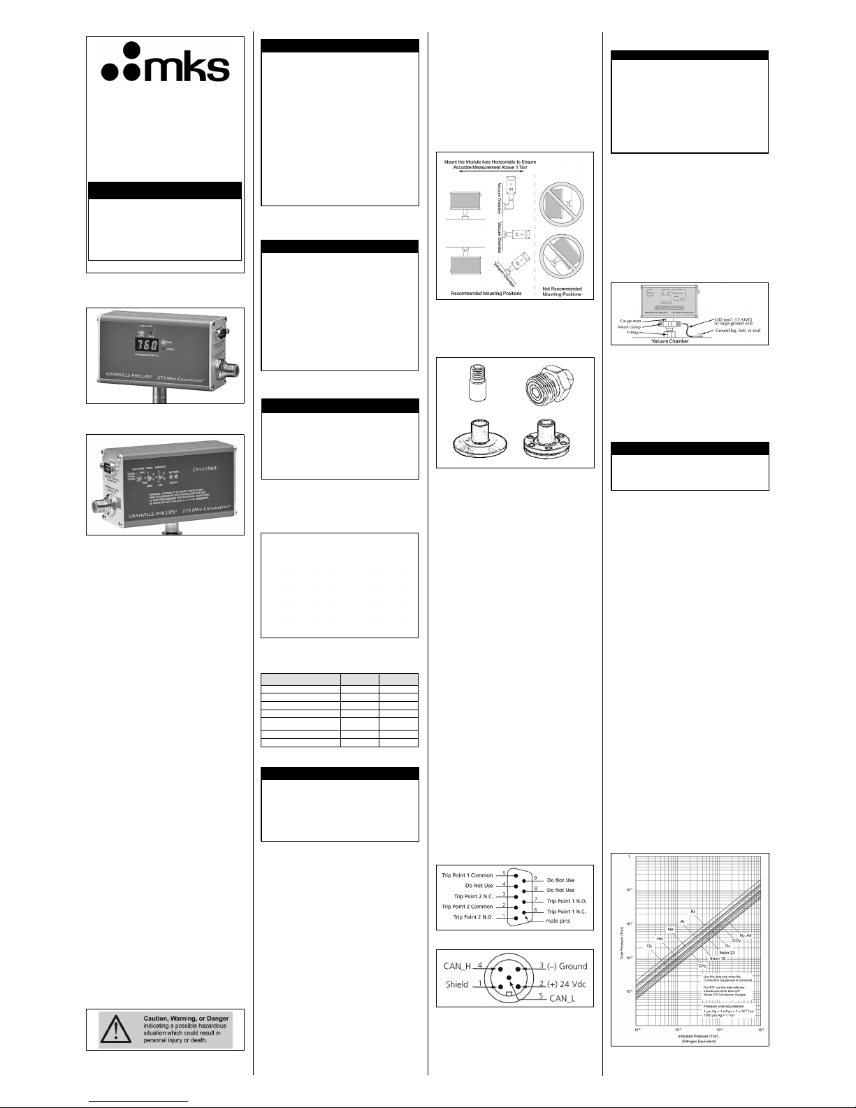
Use the following graphs to determine the indicated N
2
or
air pressure that corresponds to a specific true pressure
of 10 other commonly used process gases. Find the
point at which the horizontal line representing true
pressure intercepts the vertical line representing
indicated N
2
pressure. If the gas being used is not
included among those listed, or for a gas mixture,
generate a calibration curve using a gas-independent
transfer standard such as a capacitance manometer.
More thorough information is given in the Instruction
Manual, p/n 275563, which can be downloaded at:
www.mksinst.com.
Figure 10: True Pressure vs. Indicated Pressure for
Commonly used Gases, 10
-4
to 10-1 Torr
Series 275
Quick Start Guide for the GranvillePhillips
®
Series 275 Mini-
Convectron
®
Vacuum Gauge
Modules with DeviceNet
TM
Interface
Quick Start Guide p/n 275001- Rev. C
More detailed instructions regarding
installation, operation, and service of the
Series 275 Mini-Convectron Vacuum Gauge
Modules are provided in the Instruction
Manual, p/n 275563 which can be downloaded
from the MKS website. Go to: www.mksinst.com
and search for “275563”.
NOTICE
Connection (fitting) cm (Dim. H) inch (Dim. H)
1/8 NPT, 1/2-inch ID 2.2 0.9
1/4-inch 4 VCR, female 3.0 1.2
3/8-inch VCO male 3.9 1.5
1/2-inch 8 VCR, female 3.9 1.5
NW10KF, NW16KF, NW25KF,
NW40KF, NW50KF Flange
3.1 1.2
1.33-inch NW16CF Conflat 3.8 1.5
2.75-inch NW16CF Conflat 3.8 1.5
General Safety Notices
Do not use this instrument to measure the
pressure of flammable or explosive gases. Using
the Mini-Convectron Vacuum Gauge Module to
measure the pressure of flammable or explosive
gases can cause a fire or explosion resulting in
severe property damage or personal injury.
Exposing the Mini-Convectron Module to
moisture can cause fire or electrical shock
resulting in severe property damage or personal
injury. To avoid exposing the Module to
moisture, install it in an indoor environment. Do
not install the Module in any outdoor
environment.
To avoid measurement error or product failure
due to over pressurization, install pressure relief
valves or rupture disks in the system if pressure
substantially exceeds 1000 Torr (1333 mbar, 133
kPa).
CAUTION
High Voltage and Proper Grounding
All components of a vacuum system used with
this or any similar high voltage product must be
maintained at Earth ground for safe operation.
Be aware that grounding this product does not
guarantee that other components of the vacuum
system are maintained at Earth ground.
Verify that the vacuum port to which the MiniConvectron Module is mounted is electrically
grounded. It is essential for personnel safety as
well as proper operation that the envelope of the
gauge be connected to a facility ground.
Connect power cords only to properly grounded
outlets or sources.
WARNING
Electrical Shock or Personal Injury
The service and repair information in this
instruction guide is for the use of Qualified
Service Personnel. To avoid possible electrical
shock or personal injury, do not perform any
procedures in this manual or perform any
servicing on this product unless you are
qualified to do so.
WARNING
Operating the module above 1000 Torr
(1333mbar, 133 kPa) true pressure could cause
pressure measurement error or product failure.
To avoid measurement error or product failure due
to overpressurization, install pressure relief valves
or rupture disks in the system if pressure exceeds
1000 Torr (1333 mbar, 133 kPa).
CAUTION
Improper grounding could cause product
failure, property damage, or serious personal
injury.
To reduce the risk of product failure, property
damage, or serious personal injury, follow ground
network requirements for the facility.
• Maintain all exposed conductors at Earth ground.
• Ground the module housing to the vacuum
chamber as instructed below.
• Make sure the vacuum port to which the module
is mounted is properly grounded.
WARNING
Using the N2 calibration to pressurize a vacuum
system above about 1 Torr with certain other
gases can cause dangerously high pressures
which may cause explosion of the system.
CAUTION
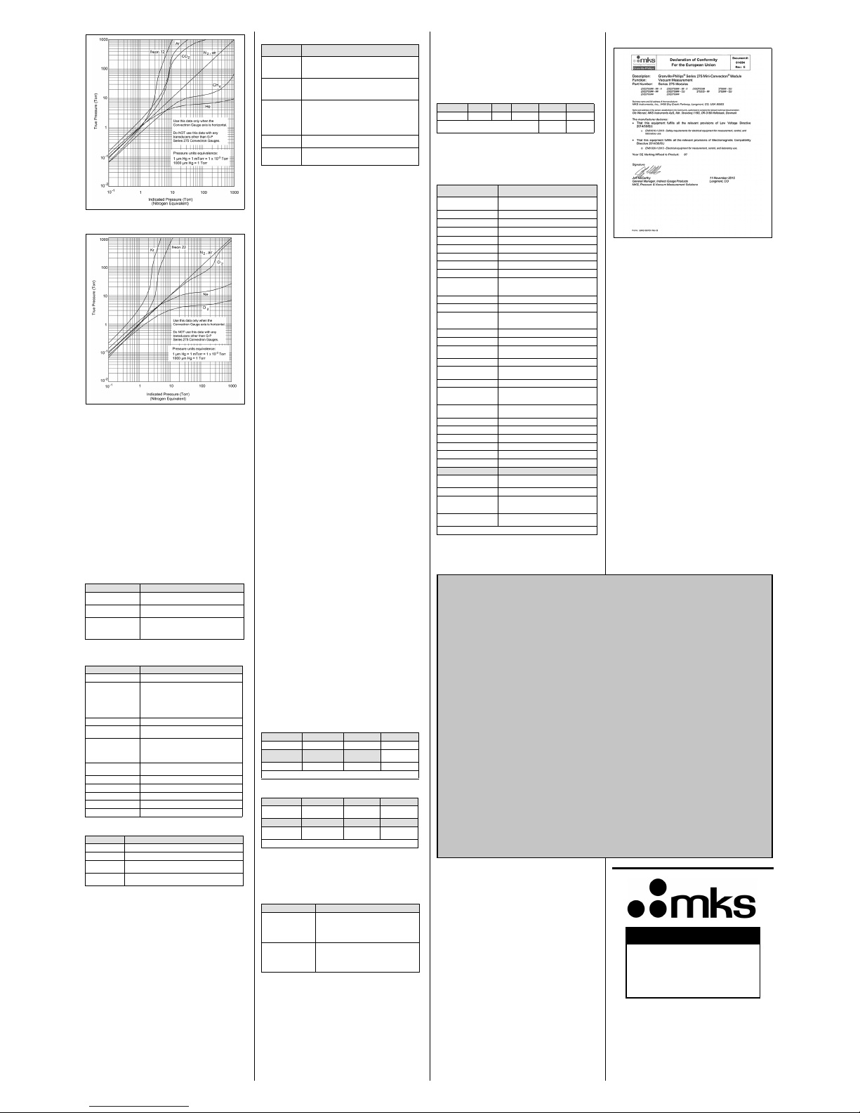
Figure 11: True Pressure vs. Indicated Pressure for
Commonly used Gases, 10
-1
to 1000 Torr
Figure 12: True Pressure vs. Indicated Pressure for
Commonly used Gases, 10
-1
to 1000 Torr
Configure the Setpoint Relays
To measure the pressure of a gas other than N2 or air,
the relay setpoints must be adjusted for the process gas.
The true pressure of a gas other than N
2
or air may be
substantially different from the pressure that the output
indicates. For example, outputs might indicate a
pressure of 10 Torr
(1.33 kPa, 13.3 mbar) for argon,
although the true pressure of the argon is 250 Torr
(33.3
kPa, 333.3 mbar)
. Such a substantial difference between
indicated pressure and true pressure can cause
overpressurization resulting in an explosion.
See Section 5.2, “Process Control Relays” in the
DeviceNet Chapter in the Instruction Manual 275563 for
detailed instructions to adjust the setpoints.
Panel Indicators and Adjustments
Table 2: Display Panel Features of Mini-Convectron
Module (See Figure 1)
Table 3: Setup Panel Features of Mini-Convectron
Module with DeviceNet (See Figure 2)
Table 4: LED Status
Table 5: Network Status
Calibration at Atmosphere and Vacuum
Pressures
Calibration improves the accuracy and repeatability of
the Convectron gauge.
An atmospheric calibration is performed on the
Convectron gauge, using N
2
, at the factory before the
module is shipped. The factory calibration sets the
atmospheric calibration point to 760 Torr
(101.3 kPa, 1013
mbar) of N
2
.
Because performance varies depending on the process
gas, it may be necessary to reset the atmospheric
calibration point if a gas other than N
2
or air is being
used. Periodic resets of the atmospheric calibration point
also improve the accuracy and repeatability of the
Convectron gauge near atmospheric pressure, even if
the process gas is N
2
or air.
During a fast pumpdown from atmospheric pressure,
thermal effects temporarily prevent the module from
measuring pressure accurately below 1 x 10
–3
Torr
(1.3 x 10⁻⁴ kPa, 1.3 x 10⁻³ mbar). After approximately 15
minutes, pressure indications in the 1 x 10⁻⁴ Tor r
(1.3 x 10⁻⁵ kPa, 1.3 x 10⁻⁴ mbar) range will be accurate.
When pressure indication in the 1 x 10
–4
Tor r (1.3 x 10
–5
kPa, 1.3 x 10⁻⁴ mbar) range has stabilized, a Convectron
gauge calibration at vacuum chamber pressure may be
performed.
The calibration may be performed at a higher pressure if
readings in the 1 x 10
–4
Torr (1.3 x 10
–5
kPa, 1.3 x 10⁻⁴ mbar)
range are not required. In the 1 x 10⁻⁴ Tor r
(1.3 x 10⁻⁵ kPa, 1.3 x 10⁻⁴ mbar) range, resolution is ±0.1
millitorr, if the Convectron gauge has been properly
calibrated at vacuum chamber pressure. If the module
frequently operates in the 1 x 10
–4
Tor r (1.3 x 10
–5
kPa, 1.3 x
10–4 mbar) range, Convectron gauge calibration at
vacuum chamber pressure should be performed
frequently.
See “Calibrating Convectron Gauge at Atmospheric
Pressure” and “Calibrating Convectron Gauge at
Vacuum Chamber Pressure” in the Operation Chapter of
the Instruction Manual, p/n 275563.
DeviceNet Operation
DeviceNet Digital Interface Setup
Use the following procedure to configure the DeviceNet
digital interface on the vacuum system and obtain a
vacuum chamber pressure.
1. Turn OFF power to the Mini-Convectron Gauge
Module.
2. Set the MAC ID switches on the Mini-Convectron
Module to the correct address position (0 - 63) for
the network on which it is installed.
3. Set the data rate switch to the appropriate baud rate
setting. See Table 3.
4. Connect the DeviceNet network cable to the
connector 275 Mini-Convectron Vacuum Gauge
Module.
5. Turn ON power to the DeviceNet connector on the
Mini-Convectron Module.
6. See Tables 6 and 7 to allocate a connection for the
module to the network master. Set the bit contents to
1 for a Polled connection, and 0 to enable Explicit
Messages.
An explicit message connection must be allocated to
allow a polled connection to be allocated. They may
be allocated simultaneously as shown in Tables 6
and 7.
7. Allocate a connection for the Mini-Convectron
Module to the network master as listed in Table 7.
Table 6: Network Master Connection
Table 7: Allocation Choice Byte Contents
The DeviceNet protocol conveys two types of messages,
as defined in Table. Once the Mini-Conve ctron Module is
operating, use the polled I/O or explicit messages to
perform the tasks listed in Table 8.
Table 8: Network Message Types
8. Configure the expected packet rate for the explicit
and polled connections, as listed in Table 9. The
default explicit message expected packet rate is 2.5
seconds. If data is requested as a slower rate, this
must change to prevent the connection from
expiring. See Tabl e 9 to disable the expe cted packe t
rate.
Table 9: Disabling the Expected Packet Rate
See Chapter 5, “DeviceNet Operation” in the Instruction
Manual 275563 for detailed information for the
DeviceNet protocol.
Product Specifications
1. Measurements will change with different gases and mixtures.
Correction parameters must be used for gases other than N
2
or Air.
2. Do not use Convectron Gauges with flammable or explosive
gases.
Declaration of Conformity
Service / Maintenance
If the product requires service, contact the MKS,
Granville-Phillips Technical Support Department at
1-303-652-4400 for troubleshooting help.
If the product must be returned to the factory for service,
request a Return Material Authorization (RMA) from
Granville-Phillips. Do not return products without first
obtaining an RMA. In some cases a hazardous materials
document may be required. The MKS/Granville-Phillips
Customer Service Representative will advise you if the
hazardous materials document is required.
When returning a product to Granville-Phillips, be sure to
package the product to prevent shipping damage. Cir cuit
boards and modules separated from the gauge assembly
must be handled using proper anti-static protection
methods and must be packaged in anti-static packaging.
Shipping damage on returned products as a result of
inadequate packaging is the Buyer's responsibility.
Service / Maintenance Procedures
Troubleshooting and gauge replacement instructions are
given in the Instruction Manual, p/n 275563, which can
be downloaded at: www.mksinst.com.
Customer Service / Technical Support
MKS Pressure and Vacuum Measurement Solutions
MKS Instruments, Inc., Granville-Phillips® Division
6450 Dry Creek Parkway
Longmont, Colorado 80503 USA
Tel: 303-652-4400
Fax: 303-652-2844
Email: mks@mksinst.com
MKS Corporate Headquarters
MKS Instruments, Inc.
2 Tech Drive, Suite 201
Andover, MA 01810 USA
Tel: 978-645-5500
Fax: 978-557-5100
Email: mks@mksinst.com
Feature Description
Relay ON The LEDs illuminate green when the
programmed setpoint is activated.
Pressure value display Provides 3-digit indication of measured
pressure.
Torr & mTorr LEDs Torr is illuminated green when the 3-digit display
indicates pressure in Torr.
mTorr is illuminated green when the 3-digit
display indicates pressure in mTorr.
Feature Description
Switches
Data rate Set the Baud Rate switch taking into account
the limits due to the length of the cable between
the DeviceNet controller and the MiniConvectron Module.
500 meters - 125K
250 meters - 250K
100 meters - 500K (default)
Baud rate 125Kb, 250Kb, 500Kb (default)
PGM (Program) Allows a programmed communication rate over
the DeviceNet interface
Node address (0 to 63) • Set the switch labeled “MSD,” to a value of 0
to 6 for the most significant (first) digit.
• Set the switch labeled “LSD,” to a value of 0
to 9 for the least significant (second) digit.
PGM Allows a programmed address setting over the
DeviceNet interface.
LSD Least Significant Digit
MSD Most Significant Digit
LEDs
NET Status of the DeviceNet network
MOD Status of the Mini-Convectron Module
Feature Description
Off No Power to the module.
Green Operating normally.
Orange The module has an unrecoverable fault, and may need
to be replaced.
Flashing
Orange-Green
The module is in self test. Refer to the Identity Object in
Volume II of the ODVA DeviceNet specification.
Feature Description
Off The module is not online.
The module has not completed the Dup_MAC_ID test
yet.
No power to the module.
Solid Green The module is on-line with connections in the
established state.
For a Group 2 Only device, the module is alloca ted to a
Master.
Blinking Green The module is on-line with no connections in the
established state.
The module has passed the Dup_MAC_ID test, is online, but has not established connections to other
nodes.
For a Group 2 Only device, the module is not allocated
to a Master.
Blinking Orange One or more I/O connections are in the Timed-Out
state.
Orange The module has detected an error that has rendered it
incapable of communicating on the network (Duplicate
MAC ID or Buss-Off).
Parameter Service Class Instance
Connection 4B
hex
31
Data Type Allocation
Choice
Master ID
STRUCT 3* 0 to 63
*Allocation Choice: 3 allocates a polled and explicit message connection.
7* 6* 5* 4*
Reserved Acknowledge
Suppression
Cyclic Change of
State
3* 2* 1 0
Reserved Bit Strobed Polled Explicit
Message
*Not Supported; Value = 0 only.
Message Type Message Purpose
Polled I/O messages • Used for time-critical, control-oriented data.
• Provides a dedicated, special purpose
communication path between a producing
application and one or more consuming
applications.
Explicit messages • Provides multipurpose, point-to-point
communication paths between two devices.
• Provides typical request/response oriented
network communications used for performing
node configuration and problem diagnosis.
Parameter Service Class Instance Attribute Data
Service 10
hex
51* 9 0
*Instance: 1 = Explicit connection, 2 = Polled
Connection
Parameter Specification
Measurement Range for
N
2
/ Air
1,2
See notes 1 and 2, below
Tor r
1x10
-4
to 1000 Torr
mbar
1x10
-4
to 1300 mbar
pascal
1x10
-2
to 130 kPa
Resolution
1x10
-4
Torr; 1x10⁻⁴ mbar; 1x10⁻² pascal
Mounting orientation Horizontal preferred
I/O connectors
2 setpoint relays 9-pin male subminiature D
DeviceNet 5-pin micro
Input power through the
DeviceNet connector
11.5 to 26.5 Vdc:
• 26 Vdc, 1.5 A
• 11.5 Vdc, 2.5 A
Setpoint relays 2-Single-pole, double-throw (SPDT)
Contact rating 1 A @ 30 Vdc resistive, 30 VAC non-inductive
Hysteresis 2% of reading for module without display;
10% of reading plus 1 significant digit for
module with optional display
Resolution 3 significant digits
DeviceNet interface
Parameters adjustable Vacuum and atmosphere calibrations,
setpoints
Messaging Polled I/O and explicit
Address 0 to 63, selected by using the Low and High
address switches
Baud rates 125K, 250K, or 500K, switch selectable
Operating temperature
0
o
C to +40 oC (32 0F to 104 0F) ambient,
indoor use only, ordinary protection from
moisture
Non-operating
temperature
-40
o
C to +70 oC (-40 0F to 158 0F)
Case material Powder-coated extruded aluminum
Weight 340 g (12 o z.) with 1/8 NPT fitting
CE Compliance
EMC EN61326-1
Safety EN61010-1
IP rating IP20
Convectron Gauge
Sensing wire filament Gold-plated tungsten (standard)
or solid platinum (optional)
Internal volume 40 cc (2.5 cu. in.)
Materials exposed to
gas
304 Stainless Steel, 17-7 stainless steel,
ceramic, Ag/Cu brazing material, Kovar,
alumina, and molybdenum
Bakeout temperature
150
o
C (302 oC) maximum, non-operating,
with electronics removed
Specifications and dimensions are subject to change without notice.
© 2016 MKS Instruments, Inc. All rights reserved.
Granville-Phillips®, Convectron®, and Mini-Convectron® are
registered trademarks, and mksinstTM is a trademark of MKS
Instruments, Inc. All other trademarks and registered trademarks
are the properties of their respective owners.
Quick Start Guide p/n 275001-Rev. C
October 2016
Template p/n DR100019-Rev. F
More detailed instructions regarding
installation, operation, and service of the
Series 275 Mini-Convectron Module are
provided in the Instruction Manual, p/n
275563 available online at
www.mksinst.com.
Notice
 Loading...