

MKS Granville-Phillips 358 Instruction Manual

Series 358
Granville-Phillips® Series 358 Micro-Ion®
Vacuum Gauge Controller
Instruction Manual
Instruction manual part number 358013
Revision B - November 2014


Series 358
Granville-Phillips® Series 358 Micro-Ion®
Vacuum Gauge Controller
This Instruction Manual is for use with all Granville-Phillips
Series 358 Micro-Ion Vacuum Gauge Controllers.
A list of applicable catalog numbers is provided on the
following page.
For Customer Service or Technical Support 24 hours per day,
7 days per week, every day of the year including holidays:
Phone: +1-800-227-8766 or +1-303-652-4691
MKS, Granville-Phillips Division
6450 Dry Creek Parkway
Longmont, CO 80503 USA
Phone: 1-303-652-4691 or 1-800-776-6543
FAX: 1-303-652-2844
Email: gp-csr@mksinst.com
Corporate Office
MKS Instruments, Inc.
2 Tech Drive, Suite 201
Andover, MA 01810 USA
Phone: 1-978-645-5500
www.mksinst.com
Instruction Manual
© 2014 MKS Instruments, Inc. All rights reserved. Granville-Phillips®, Micro-Ion®, and
Convectron
registered trademarks are the properties of their respective owners.
®
are registered trademarks of MKS Instruments, Inc. All other trademarks and
Granville-Phillips® Series 358 Micro-Ion
Vacuum Gauge Controllerule
Catalog numbers for Series 358 Micro-Ion Controllers
®
Controller for a Micro-Ion gauge, with 3-line display, electron bombardent degas,
and remote input/output interface - CE Marked
(1)
Half-rack mount: 358501 - # # # - # #
Left mount for 19-inch rack: 358502 - # # # - # #
Center mount for 19-inch rack: 358503 - # # # - # #
Black Case & Half-rack mount: 358504 - # # # - # #
Black Case & Left mount for 19-inch rack: 358505 - # # # - # #
Interface options (Slot X):
None 0
RS-232 A
RS-485/422 B
Gauge options (Slot Y):
None 0
Dual Convectron 1
Capacitance Manometer/Convectron
(1)
2
Setpoint options (Slot Z):
None 0
2 setpoint relays for Micro-Ion gauge A
6 setpoint relays, 2 per channel B
Display options (Measurement units):
To rr T
mbar M
Pascal P
Powercord options:
North America 115 V 1
North America 240 V 2
Universal Europe 220 V 3
United Kingdom 240 V 4
NOTE:
(1)
The Capacitance Manometer/Convectron Gauge option is not CE Marked.

Table of Contents
Chapter 1 Before You Begin . . . . . . . . . . . . . . . . . . . . . . . . . . . . . . 9
1.1 Caution and Warning Statements . . . . . . . . . . . . . . . . . . . . 9
1.2 Reading and Following Instructions . . . . . . . . . . . . . . . . . . 9
1.3 Damage Requiring Service . . . . . . . . . . . . . . . . . . . . . . . . . 10
1.4 Pressure Relief Devices . . . . . . . . . . . . . . . . . . . . . . . . . . . . 11
1.5 Certification . . . . . . . . . . . . . . . . . . . . . . . . . . . . . . . . . . . . 11
1.6 Warranty Information . . . . . . . . . . . . . . . . . . . . . . . . . . . . . 11
1.7 Service Guidelines . . . . . . . . . . . . . . . . . . . . . . . . . . . . . . . 11
1.8 FCC Verification . . . . . . . . . . . . . . . . . . . . . . . . . . . . . . . . . 12
Chapter 2 System Components . . . . . . . . . . . . . . . . . . . . . . . . . . . . 13
2.1 Options . . . . . . . . . . . . . . . . . . . . . . . . . . . . . . . . . . . . . . . . 17
2.2 RS-232 Specifications . . . . . . . . . . . . . . . . . . . . . . . . . . . . . 18
2.3 RS-485 Specifications . . . . . . . . . . . . . . . . . . . . . . . . . . . . . 19
2.4 Specifications . . . . . . . . . . . . . . . . . . . . . . . . . . . . . . . . . . . 20
2.5 Dimensions . . . . . . . . . . . . . . . . . . . . . . . . . . . . . . . . . . . . . 23
2.6 Mounting Options . . . . . . . . . . . . . . . . . . . . . . . . . . . . . . . . 25
Chapter 3 Initial Setup . . . . . . . . . . . . . . . . . . . . . . . . . . . . . . . . . . . 27
3.1 Controller Setup . . . . . . . . . . . . . . . . . . . . . . . . . . . . . . . . . 27
3.2 Top Cover Removal . . . . . . . . . . . . . . . . . . . . . . . . . . . . . . 27
3.3 Pressure Units Setup . . . . . . . . . . . . . . . . . . . . . . . . . . . . . . 28
3.4 Changing Units of Measure for Electrometer Module . . . . . 28
3.5 Overpressure Shutdown Adjustment . . . . . . . . . . . . . . . . . . 30
3.6 Changing Display Update Rate on Electrometer Module . . . 30
3.7 Changing Units of Measure for Convectron Gauge . . . . . . . 30
3.8 Display Update Rate Switch on Convectron Module . . . . . . 31
3.9 Changing Units of Measure for a Capacitance Manometer . 31
3.10 Process Control Setup . . . . . . . . . . . . . . . . . . . . . . . . . . . . . 32
3.11 Relay Polarity Setting . . . . . . . . . . . . . . . . . . . . . . . . . . . . . 35
3.12 RS-232 Computer Interface Setup . . . . . . . . . . . . . . . . . . . . 37
3.13 RS-485 Computer Interface Setup . . . . . . . . . . . . . . . . . . . . 42
3.14 Replacing the Controller Cover . . . . . . . . . . . . . . . . . . . . . . 47
Series 358 Micro-Ion Controller Instruction Manual - 358013 - Rev. B 5

Table of Contents
Chapter 4 Installation . . . . . . . . . . . . . . . . . . . . . . . . . . . . . . . . . . . 49
4.1 Gauge Installation Tips . . . . . . . . . . . . . . . . . . . . . . . . . . . . 49
4.2 FCC and EU Installation Requirements . . . . . . . . . . . . . . . . 49
4.3 Cable Installation . . . . . . . . . . . . . . . . . . . . . . . . . . . . . . . . 50
4.4 Environmental Conditions . . . . . . . . . . . . . . . . . . . . . . . . . . 50
4.5 Controller Installation . . . . . . . . . . . . . . . . . . . . . . . . . . . . . 50
4.6 Mounting Configurations . . . . . . . . . . . . . . . . . . . . . . . . . . 51
4.7 Line Voltage . . . . . . . . . . . . . . . . . . . . . . . . . . . . . . . . . . . . 53
4.8 Fuse Replacement . . . . . . . . . . . . . . . . . . . . . . . . . . . . . . . 53
4.9 Vacuum Gauge Installation . . . . . . . . . . . . . . . . . . . . . . . . . 53
4.10 Mounting Options . . . . . . . . . . . . . . . . . . . . . . . . . . . . . . . . 54
4.11 Grounding the System . . . . . . . . . . . . . . . . . . . . . . . . . . . . . 55
4.12 Connecting Analog Outputs . . . . . . . . . . . . . . . . . . . . . . . . 59
4.13 Connecting a Capacitance Manometer . . . . . . . . . . . . . . . . 60
4.14 Connecting Process Control Relays . . . . . . . . . . . . . . . . . . . 63
4.15 Connecting the RS-232 Computer Interface Handshake Lines 65
4.16 Connecting RS-485 Computer Interface . . . . . . . . . . . . . . . 66
Chapter 5 Preparing for Operation . . . . . . . . . . . . . . . . . . . . . . . . . 67
5.1 Preparing for Pressure Measurement . . . . . . . . . . . . . . . . . . 67
5.2 Alternate ON/OFF Gauge Control . . . . . . . . . . . . . . . . . . . . 68
5.3 Micro-Ion Gauge Remote Input/Output . . . . . . . . . . . . . . . . 68
5.4 Micro-Ion Analog Output Signal . . . . . . . . . . . . . . . . . . . . . 69
5.5 Preparing for Convectron Gauge Operation . . . . . . . . . . . . 71
5.6 Gases other than Nitrogen or Air . . . . . . . . . . . . . . . . . . . . . 71
5.7 Micro-Ion Gauge Auto ON/OFF . . . . . . . . . . . . . . . . . . . . . 80
5.8 Filament Auto ON . . . . . . . . . . . . . . . . . . . . . . . . . . . . . . . 80
5.9 Gauge Zero and Atmospheric Pressure Adjustment . . . . . . . 81
5.10 Convectron Gauge Analog Output Signal . . . . . . . . . . . . . . 82
5.11 Preparing for Capacitance Manometer Operation . . . . . . . . 84
5.12 Preparing for Process Control Operation . . . . . . . . . . . . . . . 85
5.13 Preparing to use RS-232 Computer Interface . . . . . . . . . . . . 87
5.14 RS-232 Error Messages . . . . . . . . . . . . . . . . . . . . . . . . . . . . 90
5.15 Preparing to Use RS-485 Computer Interface . . . . . . . . . . . 90
5.16 RS-485 Error Messages . . . . . . . . . . . . . . . . . . . . . . . . . . . . 93
Chapter 6 Operation . . . . . . . . . . . . . . . . . . . . . . . . . . . . . . . . . . . . 95
6.1 Controller Operation . . . . . . . . . . . . . . . . . . . . . . . . . . . . . . 95
6.2 Micro-Ion Gauge ON/OFF . . . . . . . . . . . . . . . . . . . . . . . . . 97
6.3 Degas ON/OFF . . . . . . . . . . . . . . . . . . . . . . . . . . . . . . . . . . 97
6.4 Special Considerations for Use Below 10
6.5 Gauge Electrometer Operation . . . . . . . . . . . . . . . . . . . . . . 98
6.6 Filament Selection for Electrometer Module . . . . . . . . . . . . 100
6 Series 358 Micro-Ion Controller Instruction Manual - 358013 - Rev. B
–3
Torr . . . . . . . . . 98

Table of Contents
Chapter 7 Theory of Operation . . . . . . . . . . . . . . . . . . . . . . . . . . . . 101
7.1 Micro-Ion Gauge Theory of Operation . . . . . . . . . . . . . . . . 101
7.2 Convectron Gauge Theory of Operation . . . . . . . . . . . . . . . 102
7.3 Microcontrollers and Bus Structure . . . . . . . . . . . . . . . . . . . 103
7.4 Capacitance Manometer Theory of Operation . . . . . . . . . . 103
7.5 Process Control Theory of Operation . . . . . . . . . . . . . . . . . 103
Chapter 8 Service . . . . . . . . . . . . . . . . . . . . . . . . . . . . . . . . . . . . . . 105
8.1 Service Guidelines . . . . . . . . . . . . . . . . . . . . . . . . . . . . . . . 105
8.2 Customer service . . . . . . . . . . . . . . . . . . . . . . . . . . . . . . . . 106
8.3 Damage Requiring Service . . . . . . . . . . . . . . . . . . . . . . . . . 106
8.4 Returning a Damaged Product . . . . . . . . . . . . . . . . . . . . . . 106
8.5 Troubleshooting . . . . . . . . . . . . . . . . . . . . . . . . . . . . . . . . . 107
8.6 Overpressure Shutdown . . . . . . . . . . . . . . . . . . . . . . . . . . . 109
8.7 Troubleshooting the Convectron Gauge Module . . . . . . . . . 110
8.8 Capacitance Manometer Troubleshooting . . . . . . . . . . . . . . 112
8.9 Process Control Troubleshooting . . . . . . . . . . . . . . . . . . . . . 112
8.10 RS-232 Troubleshooting . . . . . . . . . . . . . . . . . . . . . . . . . . . 113
8.11 RS-485 Troubleshooting . . . . . . . . . . . . . . . . . . . . . . . . . . . 114
8.12 Field Installation of a Module . . . . . . . . . . . . . . . . . . . . . . . 115
Series 358 Micro-Ion Controller Instruction Manual - 358013 - Rev. B 7

Table of Contents
8 Series 358 Micro-Ion Controller Instruction Manual - 358013 - Rev. B
Chapter 1 Before You Begin
CAUTION
WARNING
1.1 Caution and Warning Statements
This manual contains caution and warning statements with which you must
comply to prevent inaccurate measurement, property damage, or personal
injury.
Caution statements alert you to hazards or unsafe
practices that could result in minor personal injury or
property damage.
Each caution statement explains what you must do to prevent or
avoid the potential result of the specified hazard or unsafe
practice.
Warning statements alert you to hazards or unsafe
practices that could result in severe property damage or
personal injury due to electrical shock, fire, or explosion.
Each warning statement explains what you must do to prevent
or avoid the potential result of the specified hazard or unsafe
practice.
Caution and warning statements comply with American Institute of
Standards Z535.1–2002 through Z535.5–2002, which set forth voluntary
practices regarding the content and appearance of safety signs, symbols,
and labels.
Each caution or warning statement explains:
a. The specific hazard that you must prevent or unsafe practice that you
must avoid,
b. The potential result of your failure to prevent the specified hazard or
avoid the unsafe practice, and
c. What you must do to prevent the specified hazardous result.
System Components Initial Setup InstallationBefore You Begin
1.2 Reading and Following Instructions
Series 358 Micro-Ion Controller Instruction Manual - 358013 - Rev. B 9
You must comply with all instructions while you are installing, operating,
or maintaining the module. Failure to comply with the instructions violates
standards of design, manufacture, and intended use of the module. MKS
Instruments, Inc./ Granville-Phillips disclaim all liability for the customer's
failure to comply with the instructions.
• Read instructions – Read all instructions before installing or operating the
product.
• Retain instructions – Retain the instructions for future reference.
Chapter 1
WARNING
• Follow instructions – Follow all installation, operating and maintenance
instructions.
• Heed warnings and cautions – Adhere to all warnings and caution
statements on the product and in these instructions.
• Parts and accessories – Install only those replacement parts and
accessories that are recommended by Granville-Phillips. Substitution of
parts is hazardous.
1.3 Damage Requiring Service
Disconnect the product from the wall outlet and all power sources and refer
servicing to qualified service personnel under the following conditions:
1. When any cable or plug is damaged.
2. If any liquid has been spilled onto, or objects have fallen into, the
product.
3. If the product has been exposed to rain or water.
4. If the product does not operate normally even if you follow the
operating instructions. Adjust only those controls that are covered by
the operation instructions. Improper adjustment of other controls may
result in damage and will often require extensive work by a qualified
technician to restore the product to its normal operation.
5. If the product has been dropped or the enclosure has been damaged.
6. When the product exhibits a distinct change in performance. This
indicates a need for service.
Substitution or modifying parts can result in product
damage or personal injury due to electrical shock or fire.
• Install only those replacement parts that are specified by
Granville−Phillips.
• Do not install substitute parts or perform any unauthorized
modification to the controller.
• Do not use the controller if unauthorized modifications
have been made.
10 Series 358 Micro-Ion Controller Instruction Manual - 358013 - Rev. B
Before You Begin
WARNING
1.4 Pressure Relief Devices
Failure to install appropriate pressure relief devices for
high−pressure applications can cause product damage
or personal injury.
For automatic backfilling and other applications in which
malfunction or normal process conditions can cause high
pressures to occur, install appropriate pressure relief devices.
Suppliers of pressure relief valves and pressure relief disks can be located
via an online search, and are listed on ThomasNet.com under “Relief
Valves” and “Rupture Discs. Confirm that these safety devices are properly
installed before installing and operating the product. In addition, check
that:
1. the proper gas cylinders are installed,
2. gas cylinder valve positions are correct on manual systems, and
3. the automation is correct on automated gas delivery systems.
Vacuum gauges with compression fittings may be forcefully ejected if the
vacuum system is pressurized.
1.5 Certification MKS Instruments, Inc./ Granville-Phillips certifies that this product met its
published specifications at the time of shipment from the factory. MKS
Instruments, Inc./ Granville-Phillips further certifies that its calibration
measurements are traceable to the National Institute of Standards and
Technology to the extent allowed by the Institute's calibration facility. See
also CE Declaration of Conformity inside envelope for CE tests performed.
System Components Initial Setup InstallationBefore You Begin
1.6 Warranty Information MKS Instruments, Inc. provides an eighteen (18) month warranty from the
date of shipment for new Granville-Phillips products. The MKS Instruments,
Inc./ Granville-Phillips general terms and conditions of sale provide the
complete and exclusive warranty for MKS,Granville-Phillips Division
products. This document is located on our web site at www.mksinst.com,
or may be obtained by a contacting an MKS. Granville-Phillips Division
customer service representative.
1.7 Service Guidelines If the product requires service, contact the MKS, Granville-Phillips Division
Customer Service Department at +1-800-227-8766 or +1-303-652-4691
for troubleshooting help over the phone.
If the product must be returned to the factory for service, request a Return
Material Authorization (RMA) from Granville-Phillips. Do not return
products without first obtaining an RMA. In some cases a hazardous
materials document may be required. The MKS/Granville-Phillips Customer
Series 358 Micro-Ion Controller Instruction Manual - 358013 - Rev. B 11

Chapter 1
Service Representative will advise you if the hazardous materials document
is required.
When returning a products to Granville-Phillips, be sure to package the
products to prevent shipping damage. Circuit boards and modules
separated from the gauge assembly must be handled using proper anti-static
protection methods and must be packaged in anti-static packaging.
Granville-Phillips will supply return packaging materials at no charge upon
request. Shipping damage on returned products as a result of inadequate
packaging is the Buyer's responsibility.
For Customer Service or Technical Support 24 hours per day, 7 days per
week, every day of the year including holidays:
Phone: +1-800-227-8766 or +1-303-652-4691
Email: gp-csr@mksinst.com
MKS, Granville-Phillips Division
6450 Dry Creek Parkway
Longmont, CO 80503 USA
Phone: 1-303-652-4691 or 1-800-776-6543
FAX: 1-303-652-2844
1.8 FCC Verification This equipment has been tested and found to comply with the limits for a
Class A digital device, pursuant to Part 15 of the U.S. Federal
Communications Commission (FCC) Rules. These limits are designed to
provide reasonable protection against harmful interference when the
equipment is operated in a commercial environment. This equipment uses
and can radiate radio frequency energy and, if not installed and used in
accordance with this instruction manual, may cause harmful interference to
radio communications. However, there is no guarantee that interference
will not occur in a particular installation. Operation of this equipment in a
residential area is likely to cause harmful interference in which case the user
will be required to correct the interference at his own expense. If this
equipment does cause harmful interference to radio or television reception,
which can be determined by turning the equipment OFF and ON, the user
is encouraged to try to correct the interference by one or more of the
following measures:
• Reorient or relocate the receiving antenna.
• Increase the separation between the equipment and the receiver.
• Connect the equipment into an outlet on a circuit different from that to
which the receiver is connected.
• Consult the dealer or an experienced radio or television technician for
help.
For information about FCC and EU compliance, see FCC and EU Installation
Requirements on page 49.
12 Series 358 Micro-Ion Controller Instruction Manual - 358013 - Rev. B
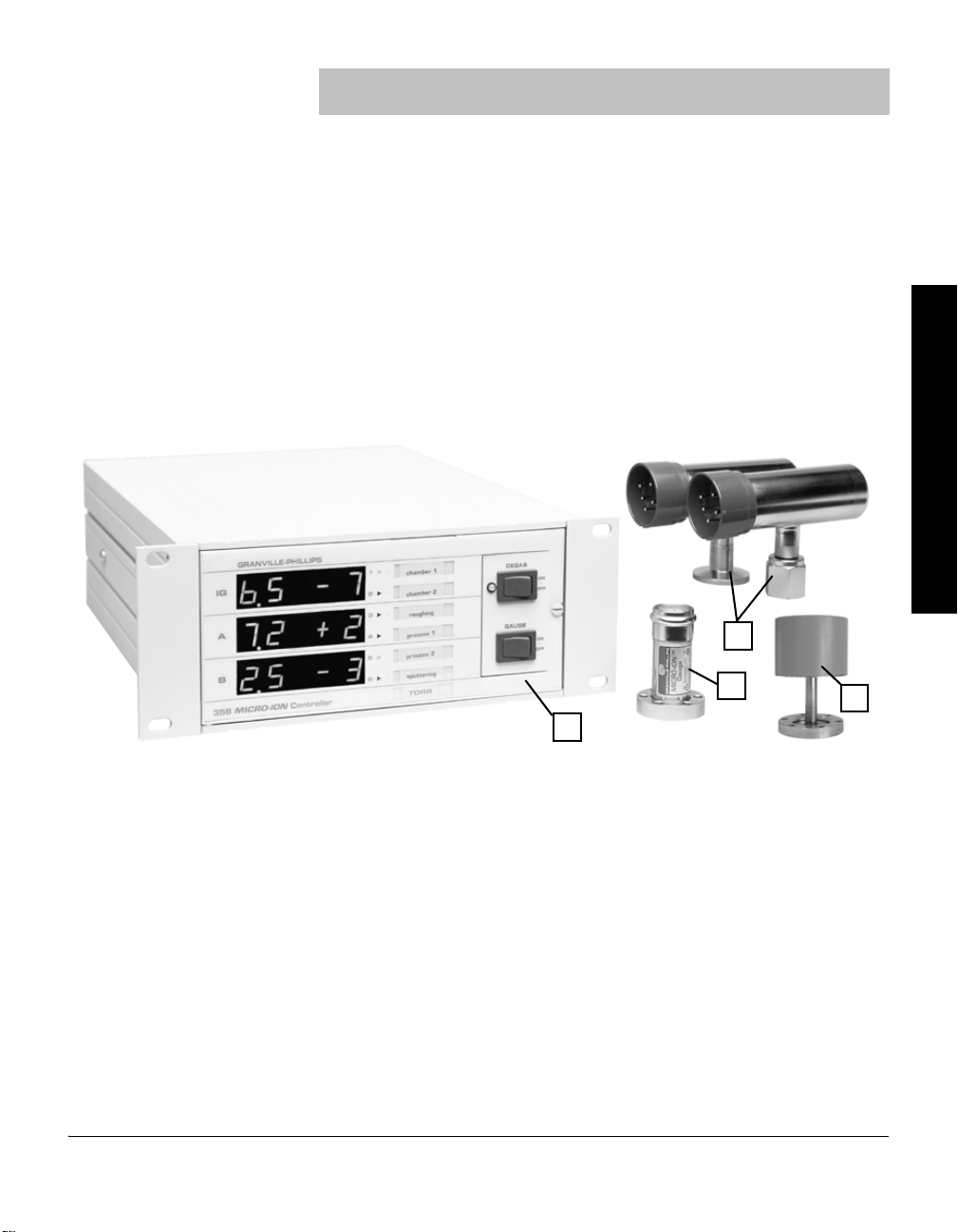
The Series 358 Micro-Ion Vacuum Measurement System can operate one
1
2
3
4
Micro-Ion Gauge along with two Convectron Gauges simultaneously, or
one Micro-Ion Gauge along with one Convectron Gauge and one
Capacitance Manometer Gauge simultaneously.
Pressure readout is via three front panel displays, analog output, and
available computer interface.
The Series 358 Micro-Ion Vacuum Measurement Controller is a modular
instrument that can easily be customized to fit most user's exact needs.
Infrequently used controls are housed behind a hinged front panel, reducing
front panel clutter and allowing the Controller to reside in a half rack space.
Figure 2-1 Micro-Ion Vacuum Measurement System
Chapter 2 System Components
System Components Initial Setup InstallationBefore You Begin
1. 358 Controller
2. Micro-Ion Gauge
3. Convectron Gauges
4. Capacitance Manometer Gauge
Series 358 Micro-Ion Controller Instruction Manual - 358013 - Rev. B 13
Chapter 2
9
8
6
1
2
3
4
5
7
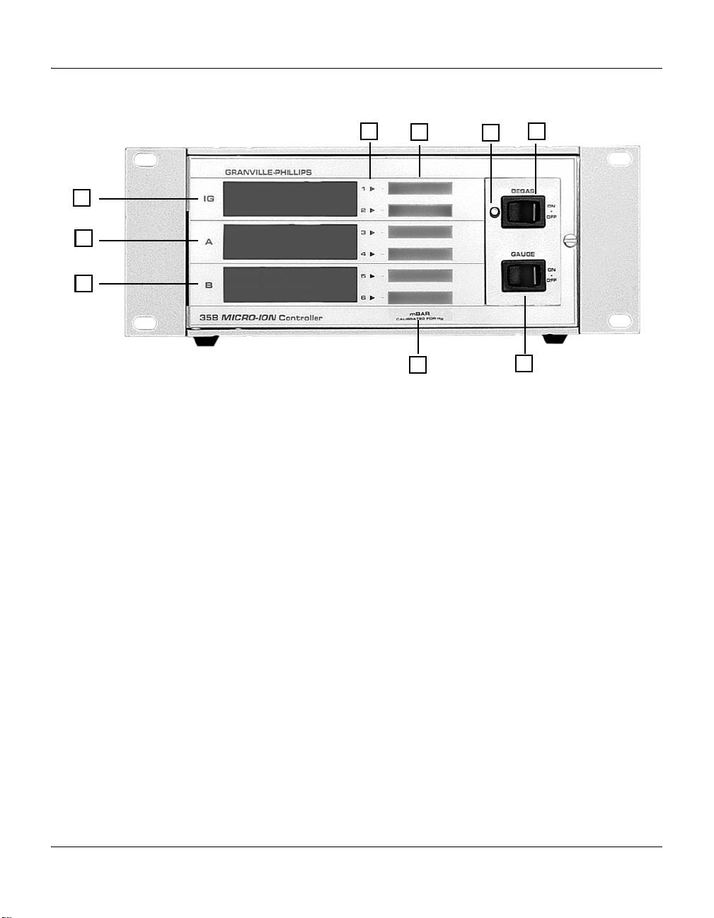
Figure 2-2 Controller Front Panel
1. Micro-Ion display 6. Degas “momentary” ON/OFF switch
2. Convectron Gauge A display 7. Degas LED
3. Convectron Gauge B or Capacitance
8. Process control channel labels
Manometer display
4. Unit of measure label: Torr, mbar or pascal,
9. Process control channel indicator lights
user selectable
5. Micro-Ion Gauge “momentary” ON/OFF switch
14 Series 358 Micro-Ion Controller Instruction Manual - 358013 - Rev. B
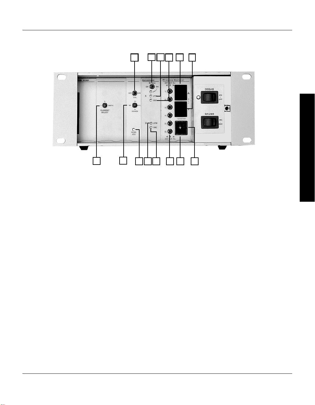
Figure 2-3 Controller Front Panel with Door Open
13
10
9
84 5
2
7
14 11
12
3
1
6
1. Filament select switch: filament 1, filament 2, or both
2. Pressure range selector
3. Sensitivity adjustment
System Components
System Components Initial Setup InstallationBefore You Begin
4. Atmosphere adjustment, Convectron or Capacitance Manometer gauge B
5. Vacuum zero adjustment, Convectron or Capacitance Manometer gauge B
6. Process control setpoint 3-position manual override switches.
Center = relay is controlled automatically.
Left = relay is deactivated.
Right = relay is activated.
7. Process control channel indicator
8. Process control channel selector thumbwheel
9. “Down” process control setpoint pressure set pushbutton
10. “Up” process control setpoint pressure set pushbutton
11. Vacuum zero adjustment, Convectron gauge A
12. Atmosphere adjustment, Convectron gauge A
13. Micro-Ion gauge auto ON switch (via Convectron gauge)
14. Calibration / sensitivity ON switch
Series 358 Micro-Ion Controller Instruction Manual - 358013 - Rev. B 15
Chapter 2
1
2
3
4
5
6
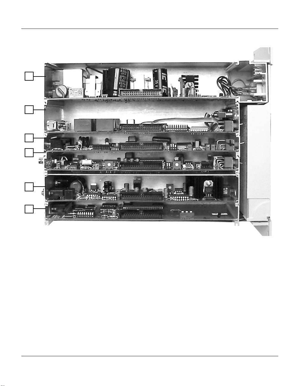
Figure 2-4 Controller Top View with Cover Removed
1. Power supply board
2. Process control setpoint option board
3. Convectron or Capacitance Manometer gauge option board
4. Electrometer board
5. Filament/grid supply board
6. Interface option board (RS-232 or RS-485)
16 Series 358 Micro-Ion Controller Instruction Manual - 358013 - Rev. B
2.1 Options
1
12
2
3 54 8
9
7
10
1113
6
System Components
Process Control Relay
A 2-setpoint or 6-setpoint relay option can either be factory installed or
added at any time by the user. The set points are adjustable from
atmosphere to 1 x 10
indication.
RS-232 or RS-485/422 Computer Interface Module
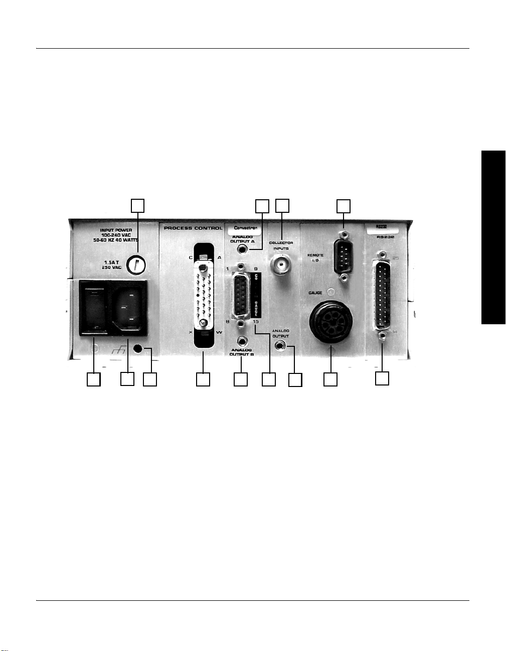
Figure 2-5 Controller Rear Panel (with RS-232 Option)
Provides readout of pressure, process control relay status, and Micro-Ion
Gauge control.
–10
Torr with override switches and front panel status
System Components Initial Setup InstallationBefore You Begin
1. Power switch 8. Micro-Ion Gauge power connector
2. Power input connector 9. DB25S connector for RS-232 computer interface
3. Grounding lug to be connected to Earth ground
with 12 AWG conductor
4. 20-pin connector for process control relay
contacts
5. Connector for analog output voltage from
Convectron or Capacitance Manometer gauge B
6. DA15P connector for Dual Convectron or
10. DE9S connector for remote parameter selection
inputs/outputs
11. Collector connector for Micro-Ion gauge
12. Connector for analog output voltage from
Convectron gauge A
13. Fuse holder
Capacitance Manometer gauge cable
7. Connector for analog output voltage from
Micro-Ion Gauge
Series 358 Micro-Ion Controller Instruction Manual - 358013 - Rev. B 17
Chapter 2
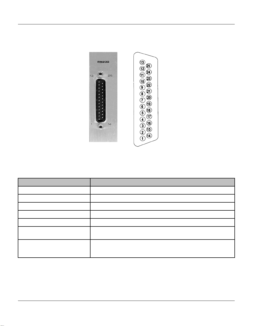
DB–25S connector
See Section 3.12 for
connector pin assignments.
2.2 RS-232 Specifications
Figure 2-6 RS-232 Wiring Connector
Table 2-1 RS-232 Specifications
Item Specification
Format EIA standard RS-232-C, half duplex, asynchronous
Data Rates 75,150,300,600,1200,2400,4800,9600 baud
Character length 7 or 8 bit ASCII, switch selectable
Parity Odd, even, or none, switch selectable
Stop bits 1 or 2. 8 character bits plus parity allows only 1 stop bit
Handshake Outputs: DTR,RTS. RTS polarity selectable. Inputs: DSR, CTS, DCD. May be
forced to logic “TRUE” with switches
Logic levels Inputs: Logic 1, 2.0 Vdc minimum,15 Vdc maximum, logic 0, –15 Vdc minimum,
18 Series 358 Micro-Ion Controller Instruction Manual - 358013 - Rev. B
0.75 VDC maximum
Input Current: 4.0 mA max @ Vin = +15 Vdc, –4.0 mA max @ Vin = –15 Vdc
2.3 RS-485 Specifications
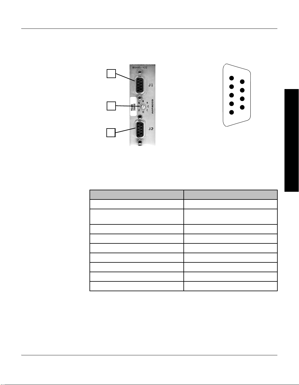
1
3
2
1) J 1 DE9P
Connector for
RS-485/422
computer interface
2) Address dial
3) J 2 DE9P
Connector for
RS-485/422
computer interface
5
9
1
6
See Section 3.12 for connector pin assignments
Figure 2-7 RS-485 Wiring Connector
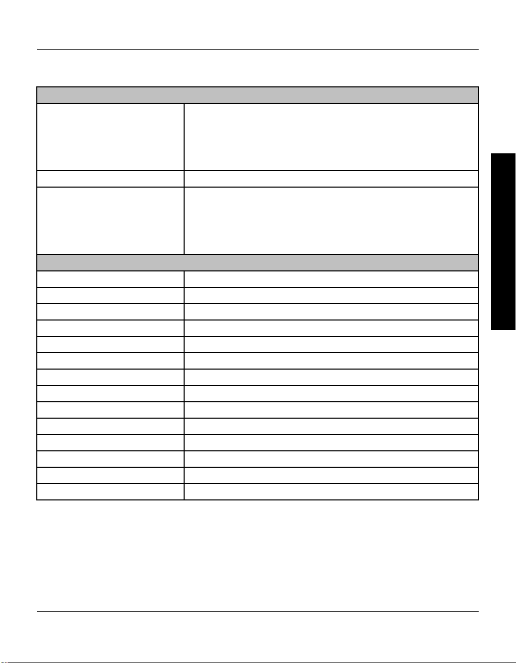
Table 2-2 RS-485 Specifications
Item Specification
Format Half duplex, asynchronous.
Data Rates 19200, 9600, 4800, 2400, 1200, 600, 300,
Character Length 8 bit or 7 bit ASCII
Parity No parity, even, or odd
Stop Bits 1 or 2
Handshake None.
Address 256 selectable combinations
Number of Connections Up to 32 devices
Total Cable Length 4000 ft. maximum
System Components
System Components Initial Setup InstallationBefore You Begin
150 baud
Series 358 Micro-Ion Controller Instruction Manual - 358013 - Rev. B 19

Chapter 2
2.4 Specifications
Table 2-3 Specifications
Micro-Ion System
Pressure Range for N
Lower Measurement Limit
Upper Measurement Limit
or air*
2
< 1 x 10⁻⁹ Torr (1.3 x 10⁻⁹ mbar) (1.3 x 10⁻⁷ pascal) at 4 mA emission
Atmosphere
Controller
Electronic accuracy Typical ± 3% of reading at ambient temperature of 25 ± 5
Display
Units
Update Rate
Digital, green LED, 2 digits plus exponent
Torr, mbar, pascal (user selectable)
0.5 sec. typical as shipped. Internal switch selectable to 3 sec./reading averaged
°C
Filament Control Switch selectable: filament 1, filament 2, or both
Degas Electron bombardment, approximately 4 W with 2 minute timer
Maximum Micro-Ion Gauge
Cable Length 15 m (50 ft) with standard cable
Remote I/O
Gauge and Degas On/Off Inputs
Momentary ground controls filament selection and degas
Less than 0.4 Vdc @ 10 μA for 25 msec (minimum). Must be greater than 3.5 Vdc
for 105 msec (minimum) before next low state
Filament Status Relay Contact Rating
Micro-Ion gauge status relay rated at 1.0 A, 30 Vdc
Environment Indoor use
Altitude up to 2000 meters
Temperature 0
°C to 40 °C
Maximum relative humidity 80% for temperatures up to 31 °C decreasing linearly
to 50% relative humidity at 40 °C
Transient overvoltages according to installation category (overvoltage category) II
Pollution degree 2 in accordance with IEC 664
Operating Temperature 0 °C to +40 °C ambient, noncondensing
Non-operating Temperature –40 °C to +70 °C
Analog Output 0 to 10 Vdc, logarithmic, 1 V/decade
Overpressure Protection Gauge turns OFF if pressure rises above factory set upper pressure limit
Emission Current Settings 0.02 mA (MV), 1 mA (HV), 4 mA (UHV)
Operating Voltage and Power 100 to 240 VAC, 50 to 60 Hz, 50 W maximum
Fuse Rating 250 V, 1.6 A, 5 x 20mm Time Lag (T), low breaking capacity
Weight 1.8 kg (4 lb)
* Measurement limits are determined by the controller emission current setting and X-ray limit of the gauge.
20 Series 358 Micro-Ion Controller Instruction Manual - 358013 - Rev. B
System Components
Table 2-3 Specifications
Controller Options
Process Control
Relay Configuration
Contact Rating
Channels
Hysteresis
Setpoint adjustment
SPDT, Form C
5A @ 120 VAC, 4A @ 240 VAC resistive or 5A @ 30 Vdc
6 maximum, 2 per operating gauge maximum
10%
Digital, 2 significant digits plus exponent
Digital Interfaces RS-232 or RS-485/422
Dual Convectron Gauge
Pressure Range
Display Units
Maximum Cable Length
Analog Output
Display Resolution
999 to 1 x 10
Torr, mbar, pascal (user selectable)
150 m (500 ft)
0 to 7 V, logarithmic, 1 V/decade, adjustable offset of +1 to –7 Vdc
2 significant digits, except for lowest two decades
–4
Torr for N2 or air
Micro-Ion Gauge
Sensitivity 3/Torr to 50/ Torr (factory setting is 20/Torr)
Emission Current 20 μA, 1 mA, 4 mA
Collector Potential 0 V
Grid Potential +180 Vdc
Filament Potential +30 Vdc
Degas Electron bombardment: 15 mA DC, 250 Vdc, auto shutoff, 2 minutes
Analog Output 0 to 10 Vdc, logarithmic, 1 V/decade
Filaments Dual yttria-coated iridium, or tungsten
†
Operating Temperature 0 °C to +50 °C ambient, noncondensing
Gauge Bakeout Temperature +200 °C maximum
Cable Bakeout Temperature +150 °C maximum
Materials Exposed to Vacuum Vacuum fired, UHV compatible
Internal Volume 10.8 cm
Weight 0.1 kg (4 oz.) (with 1 5/16 in. Conflat
3
(0.66 in.3)
®
type flange)
† Tungsten filaments are for applications involving gases containing fluorine, chlorine, or other gas species that poison
yttria-coated iridium filaments. Tungsten filaments are not recommended for general vacuum applications because they may
burnout when exposed to high pressures.
System Components Initial Setup InstallationBefore You Begin
Series 358 Micro-Ion Controller Instruction Manual - 358013 - Rev. B 21
Chapter 2
Table 2-3 Specifications
Convectron Gauge
Pressure Range 1 x 10
Display Resolution 2 significant digits, except for 1 significant digit in 1 x 10
Gas Type N
–4
Torr to 990 Torr, N2 equivalent
, air (for direct reading)
2
–4
Torr decade
Display Update Time 0.5 sec. typical. Switch selectable to 3 sec./reading, averaged
Analog Output 0 – 7 Vdc, logarithmic, 1 V/decade
Ion Gauge Turn-On Range Less than or equal to 100 mTorr (1 x 10
-1
Torr)
Sensor Material Gold-plated tungsten
Mounting Orientation Gauge axis must be horizontal to provide accurate measurement above about
1 Torr
Operating Temperature +4 °C to +50 °C ambient, noncondensing
Bakeout Temperature +150 °C maximum, nonoperating, cable disconnected
Cable Bakeout Temperature +105 °C maximum
Ion Gauge Pressure Range* See Table 3-1 on page 30
22 Series 358 Micro-Ion Controller Instruction Manual - 358013 - Rev. B
System Components
Table 2-3 Specifications
Capacitance Manometer Specifications
Gauge Type Any capacitance manometer transducer that requires ± 15 Vdc power at < 250 mA
Accuracy 0.01% of full scale (as limited by display resolution)
Display Resolution Highest 3 decades – 2 digits, lowest decade – 1 digit, scientific notation
Maximum Pressure Scales 1, 10, 100, 1000 Torr max heads, 4 decades of pressure
Display Update Time Unfiltered: 0.5 sec. typical. Switch selectable filtering: 3 sec. (average of 6
Output to Head ± 15 V ± 2% at 250 mA
Input from Head 0 to 10 Vdc into 100 k
Analog Output 5 mA maximum
Analog Output Speed Limited by transducer speed
Cable Connection Cable termination is bare tinned wire, user terminates to transducer
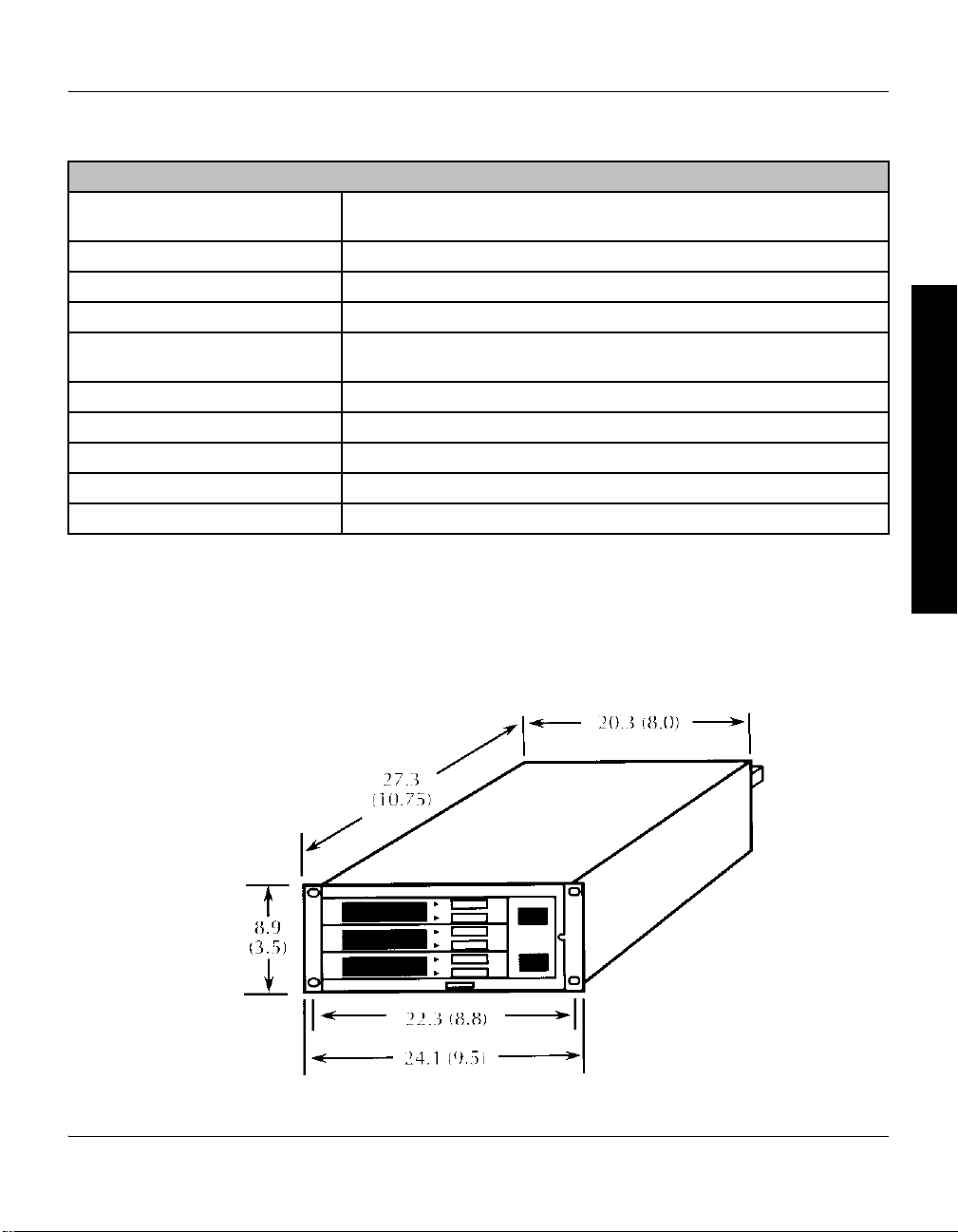
2.5 Dimensions The dimensions of the controller in a half rack (standard) mounting are
and outputs 0–10 Vdc proportional to pressure
readings)
Ω
shown in Figure 2-8.
Dimensions are in centimeters (inches).
System Components Initial Setup InstallationBefore You Begin
Figure 2-8 Controller Dimensions
Series 358 Micro-Ion Controller Instruction Manual - 358013 - Rev. B 23
Chapter 2
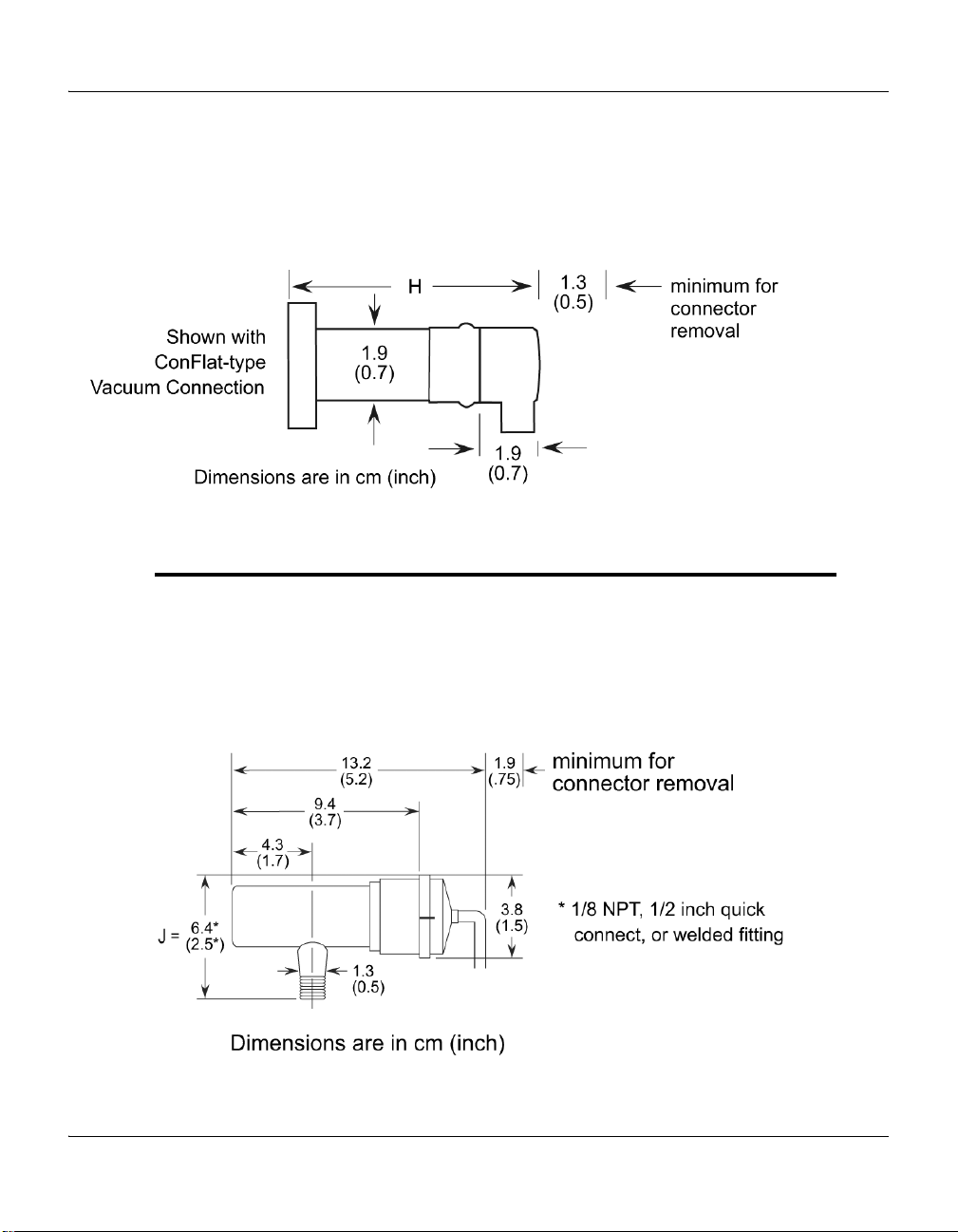
Figure 2-9 Micro-Ion Gauge with Connector
The dimensions of the Micro-Ion gauge are shown in Figure 2-9.
Dimensions are in cm (in.).
H dimensions are given in Table 2-4.
The dimensions of the Convectron gauge are shown Figure 2-10.
Dimensions are in cm (in.).
J dimensions are given in Table 2-4.
Figure 2-10 Convectron Gauge with Connector
24 Series 358 Micro-Ion Controller Instruction Manual - 358013 - Rev. B

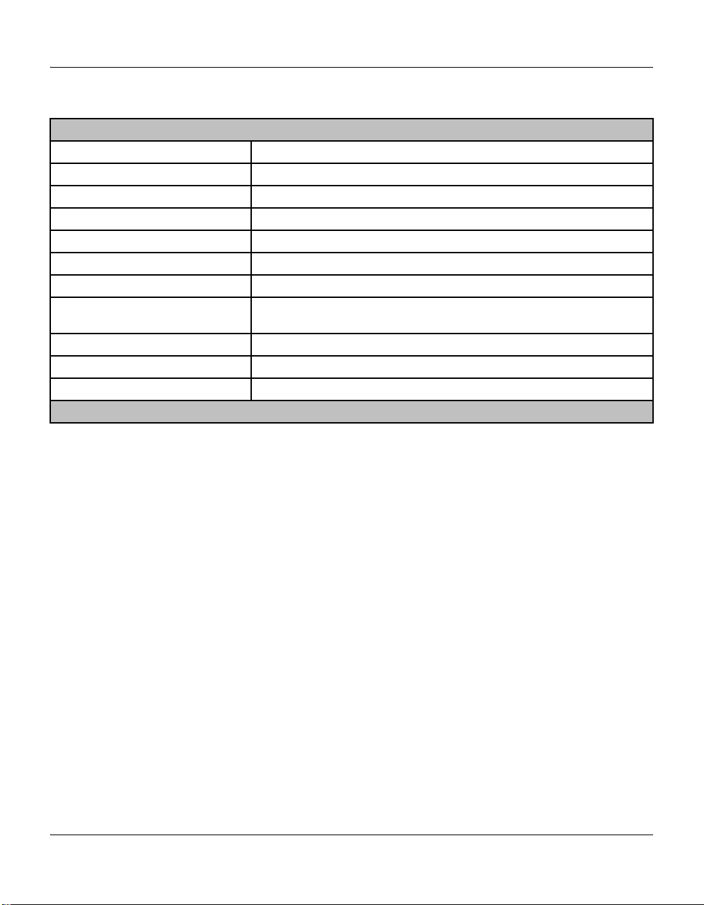
Table 2-4 Fittings
Fitting Description Dimension H Dimension J
0.75 inch port diameter
1.0 inch port diameter
15 mm port diameter
18 mm port diameter
9.4 cm (3.7 in.)
9.4 cm (3.7 in.)
9.4 cm (3.7 in.)
9.4 cm (3.7 in.)
Not applicable
Not applicable
Not applicable
Not applicable
System Components
1/4 inch VCR
1/2 inch VCR type
NW16KF flange
NW25KF flange
NW40KF flange
1.33 inch ConFlat
2.75 inch ConFlat
®
type
Not applicable
8.6 cm (3.4 in.)
7.3 cm (2.9 in.)
7.3 cm (2.9 in.)
7.3 cm (2.9 in.)
®
7.3 cm (2.9 in.)
7.3 cm (2.9 in.)
VCR® is a registered trademark of Swagelok Company
8.1 cm (3.2 in.)
8.1 cm (3.1 in.)
6.9 cm (2.7 in.)
6.9 cm (2.7 in.)
Not applicable
6.4 cm (2.5 in.)
6.4 cm (2.5 in.)
2.6 Mounting Options The controller can be ordered with a variety of mounting options to fit your
needs. This includes half rack (standard), full rack, or two units in a full rack.
See Controller Installation on page 50 and Figure 4-1 on page 52.
System Components Initial Setup InstallationBefore You Begin
Series 358 Micro-Ion Controller Instruction Manual - 358013 - Rev. B 25

Chapter 2
26 Series 358 Micro-Ion Controller Instruction Manual - 358013 - Rev. B
Chapter 3 Initial Setup
3.1 Controller Setup Now is a convenient time to make any required switch changes before
mounting the Controller in its desired location.
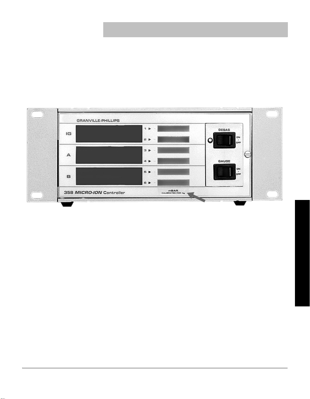
If the pressure display units of measure are correct (see Figure 3-1), and you
do not want to change the degas power timer from the factory setting of 10
minutes, skip to Process Control Setup on page 32.
Figure 3-1 Units of Measure Label
System Components Initial Setup InstallationBefore You Begin
If you want to change the units of measure, the display rate, or the degas
timer, you must remove the top cover of the Controller.
3.2 Top Cover Removal 1. With power OFF, remove any cables from Controller rear panel.
2. Observe antistatic precautions to avoid damaging static sensitive
components inside the chassis. Use a grounded, conductive work
surface. Do not handle integrated circuits (IC) devices more than
necessary, and only when wearing a high impedance ground strap.
(A high impedance helps protect human life in case of inadvertent
contact with high voltage.)
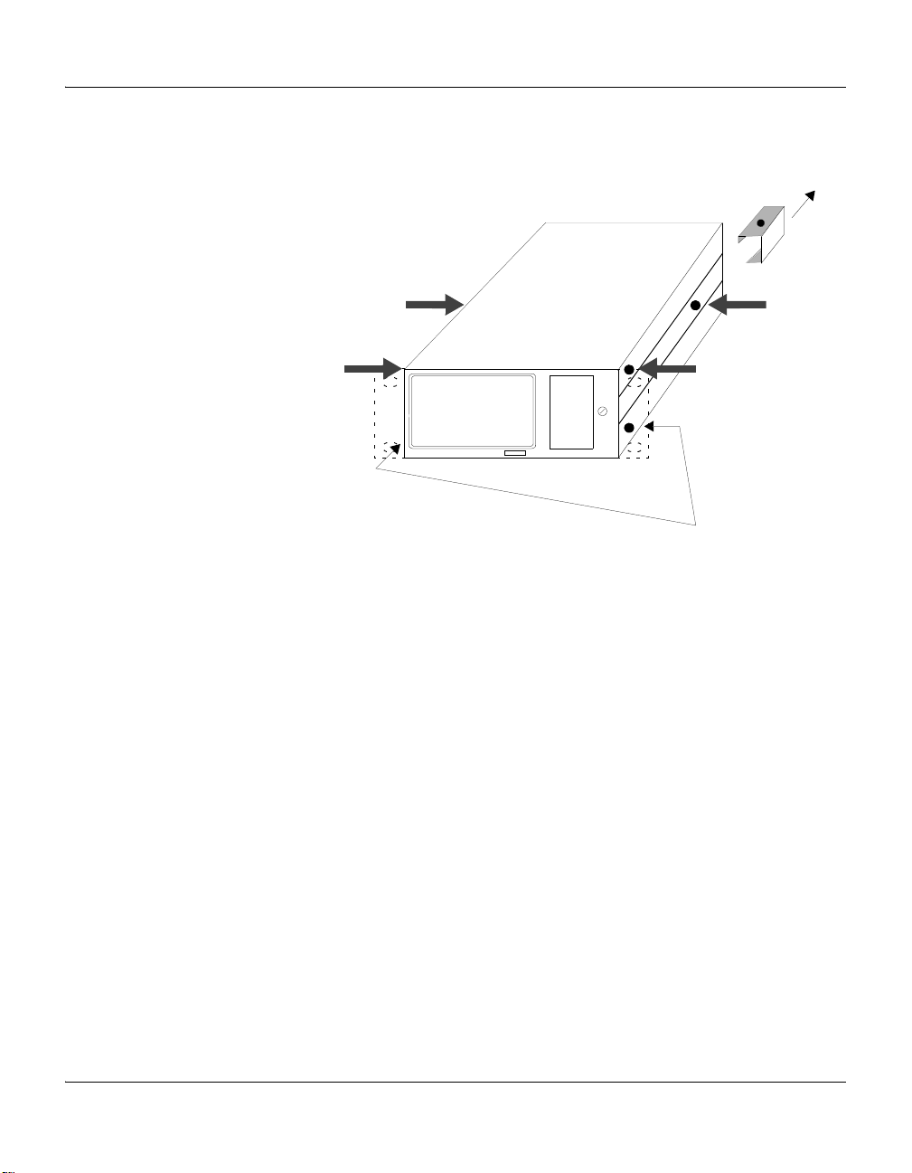
3. Remove the four Phillips head screws identified in Figure 3-2. If the
unit is equipped with a rear bracket, remove the Phillips head screw on
the bracket, and slide the bracket off.
Series 358 Micro-Ion Controller Instruction Manual - 358013 - Rev. B 27
Chapter 3
Bracket
Do not remove the two
lower front screws
Figure 3-2 Location of Screws for Top Cover Removal
3.3 Pressure Units Setup
If units of measure are as desired (see Figure 3-1), skip to Changing Display
Update Rate on Electrometer Module on page 30.
3.4 Changing Units of Measure for Electrometer Module
Your unit will have been shipped from the factory preset to display the unit
of measure, Torr, mbar, or pascal, that you requested. Selection between
Torr and mbar units is done by adjusting the Micro-Ion gauge tube
sensitivity to the appropriate units. For example, a tube has a sensitivity of
20/Torr or 15/mbar. Thus, for this tube, adjusting the sensitivity for a display
reading of 2.0+1 will result in display of pressure in Torr (see Sensitivity
Adjustment on page 99). Adjusting to 1.5+1 will result in display in mbar.
If you want to change pascal units, change the switch on the electrometer
module as follows:
1. Shut OFF power to the Controller.
2. Remove the top cover as described in Top Cover Removal on page 27.
3. Locate the Micro-Ion gauge electrometer module. See Figure 2-4 and
Figure 3-3.
4. Locate the Unit of Measure display units control switch.
28 Series 358 Micro-Ion Controller Instruction Manual - 358013 - Rev. B
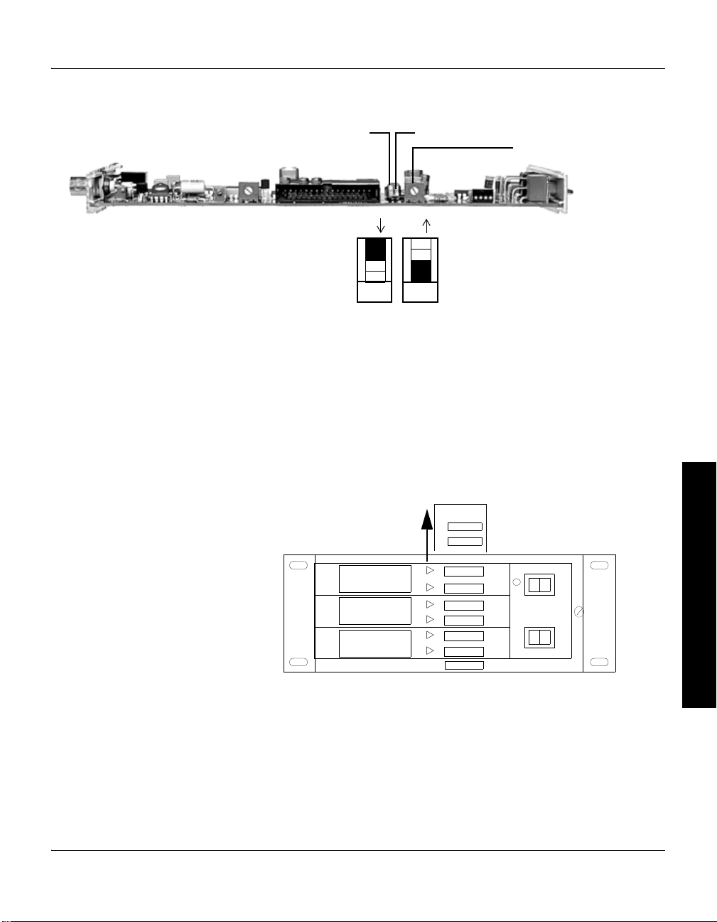
Figure 3-3 Ion Gauge Electrometer Module TopView
Unit of Measure
Slow Update
Overpressure Shutdown
Potentiometer
Units of measure switch
ON and OFF positions
X
OFF
X
ON
1
2
IG
7.5 – 6
A
B
6.4 – 2
3.2 + 2
1
DEGAS
-
2 -
3 -
ON
OFF
GAUGE
ON
OFF
358 Micro-Ion Controller
4 -
5 -
6 -
TORR
5. Set the switch to the desired position: Off = Torr/mbar units;
On = pascal units.
You must also change the setting of the unit of measure switch on the
Dual Convectron gauge as described in Changing Units of Measure for
Convectron Gauge on page 30.
6. To change the units of measure label on the front of the Controller,
open the door and lift the label card from its slot in the top of the front
panel. Units of measure labels are included in the mounting hardware
kit.
Initial Setup
System Components Initial Setup InstallationBefore You Begin
Figure 3-4 Removing the Units of Measure Label Card
Series 358 Micro-Ion Controller Instruction Manual - 358013 - Rev. B 29
Chapter 3
3.5 Overpressure Shutdown Adjustment
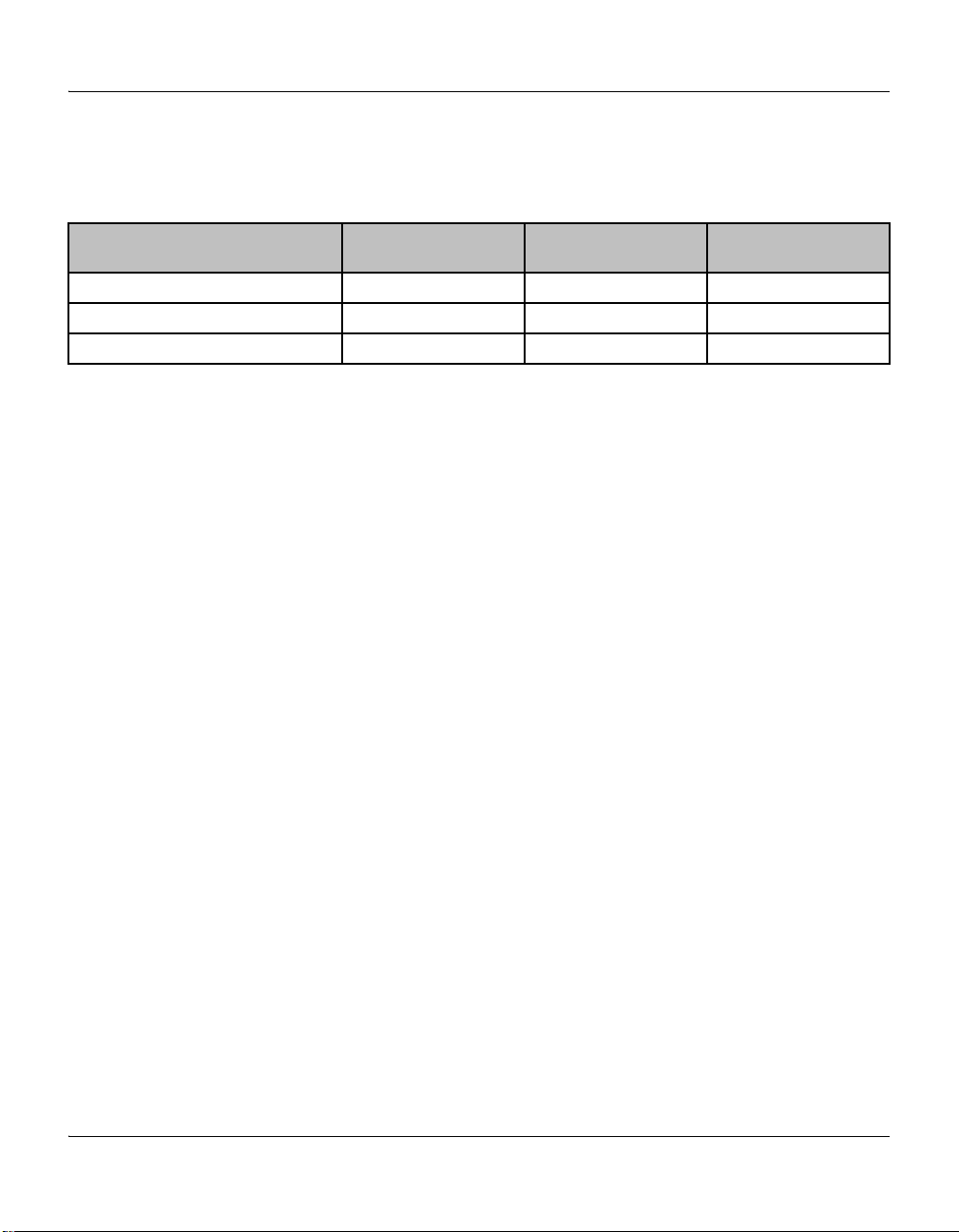
Table 3-1 Pressure Range Settings
Pressure Range
Designation
Emission Current 20 μA 1 mA 4 mA
Recommended Upper Limit, Torr 5 x 10
Recommended Lower Limit, Torr 1 x 10
This control is factory set so the ion gauge will shut down when the pressure
rises above the levels given in Table 3-1.
MV
(Medium Vacuum)
–2
–6
HV
(High Vacuum)
–4
8 x 10
–7
1 x 10
To adjust the overpressure shutoff point to a different level:
1. Maintain system pressure at the desired shutoff point.
2. Rotate the overpressure adjustment potentiometer fully
counterclockwise.
3. Turn ON the ion gauge.
4. Rotate the adjustment potentiometer clockwise slowly until the ion
gauge turns OFF.
3.6 Changing Display Update Rate on Electrometer Module
When “ON”, the Slow Update switch on the electrometer module enables
pressure averaging. The display will be updated approximately every 3
seconds. When “OFF”, the update period is approximately 0.5 seconds.
Refer to Figure 3-3 on page 29.
UHV
(Ultrahigh Vacuum)
–4
2 x 10
Less than 1 x 10
–9
3.7 Changing Units of Measure for Convectron Gauge
The Series 358 Controller is shipped from the factory preset to display the
units of measure, Torr, mbar, or pascal, that you requested. To change the
units of measure for the Convectron Gauge:
1. Turn OFF power to the Controller.
2. Remove the top cover as described in Top Cover Removal on page 27.
3. Locate the Convectron gauge module. See Figure 2-4 and Figure 3-5.
4. Locate the mbar and pascal units switches.
5. Leave both switches “OFF” for Torr units. Turn ON the switch for either
mbar or pascal units.
6. Modify the units of measure of the electrometer module to be
consistent with the Convectron gauge. (See Changing Units of Measure
for Electrometer Module on page 28.)
7. Slip the label card out of the top of the front panel and apply the
appropriate pressure units label. See Figure 3-4.
8. Replace the top cover as described on page 47.
30 Series 358 Micro-Ion Controller Instruction Manual - 358013 - Rev. B
 Loading...