

MKS GMW-25 Operation Manual

OPERATION MANUAL
GMW-25
RF Plasma Generator
HIGH RF VOLTAGES MAY BE PRESENT AT THE OUTPUT OF THIS
UNIT. All operating personnel should use extreme caution in handling
these voltages and be thoroughly familiar with this manual.
DO NOT USE ANY CFC (CHLOROFLUOROCARBON) SOLVENT IN THE
MAINTENANCE OF THIS PRODUCT. In recognition of our responsibility to protect
the environment, this product has been manufactured without the use of CFC's. The
CFC's
QUALITY
ISO 9001
SYSTEM
The material contained in this manual is subject to change without notice. No part of this manual may be
reproduced or utilized in any form or by any means, electronic or mechanical, including photocopying or
electronic transmission or other means of reproduction or distribution without prior written consent of MKS,
ENI Products. The drawings, specifications and other technical information contained in this manual are the
property of MKS, ENI Products and shall not be copied, reproduced or used in any way, in whole or in part, as
the basis of manufacture or sale of similar items without the prior written consent of MKS, ENI Products.
no-clean flux now used in all soldering operations may leave a small inert residue that
will not affect the performance of the product. The use of CFC's for cleaning or
maintenance may result in partial liquification of the no-clean flux residue, which will
damage the unit and void the warranty.
This product is manufactured at an MKS Instruments’ ISO-9001:2000-QualitySystem-compliant facility.
Notice
Manual Order Number: 1050-001 Copyright © 1996 MKS Instruments, Inc. All rights reserved.
Revision Level: B 10/07/04 MATCHWORK
®
is a registered trademark of MKS Instruments, Inc.

Warranty
MKS, ENI Products warrants to the original purchaser for a period of one year from the date of
delivery, each instrument to be free from defects in materials and workmanship. For a period of one
year, MKS, ENI Products will, at its option, adjust, repair, or replace defective parts, without charge to
the original purchaser, so that the instrument performs according to its specifications.
When warranty service is required, the instrument must be returned, transportation prepaid, to
the factory or to one of MKS, ENI Products' designated service centers. If, in our opinion, the
instrument has been damaged by accident, unreasonable use, buyer-supplied software or interfacing,
improper site preparation or maintenance, or abnormal conditions of operation, repairs will be billed
at standard rates. In this case, an estimate will be submitted before the work is started.
THIS LIMITED WARRANTY IS EXCLUSIVE AND MKS, ENI PRODUCTS MAKES NO OTHER
WARRANTIES, EXPRESS OR IMPLIED, AND ALL OTHER EXPRESS ORAL OR WRITTEN
WARRANTIES AND ALL WARRANTIES IMPLIED BY LAW, INCLUDING ANY WARRANTIES OF
MERCHANTABILITY
QUALITY ARE EXCLUDED
LIABLE FOR SPECIAL, INDIRECT, INCIDENTAL OR CONSEQUENTIAL DAMAGES RESULTING
FROM BREACH OF ANY WARRANTY, WHETHER EXPRESS OR IMPLIED, INCLUDING ANY
IMPLIED WARRANTY OF MERCHANTABILITY OR FITNESS FOR A PARTICULAR PURPOSE, OR
FROM ANY CAUSE WHATSOEVER, INCLUDING NEGLIGENCE. Buyer's sole and exclusive
remedy under this warranty shall be repair or replacement as set forth above, or if MKS, ENI
Products is unable to repair or replace the defective part within a reasonable time, a refund of the
price of the part or goods that give rise to the warranty claim.
OR FITNESS FOR A PARTICULAR PURPOSE OR OTHER WARRANTY OF
AND DISCLAIMED. IN NO EVENT SHALL MKS, ENI PRODUCTS BE
Service And Technical Assistance
For Service or Repair contact the closest Customer Service Department with the following
information:
• Model and serial number
• Purchase order number
• Detailed description of malfunction
• Your company's "Bill To" and "Ship To" address
You will receive a RMA (Return Materials Authorization) number, the warranty status of the unit to be
returned and estimated repair charge, if any. The RMA number is your authorization number. Please
type this number on your purchase order and shipping label. After MKS, ENI Products receives the
unit, a firm quote and estimated date of completion will be given.
For Technical Assistance for your particular application, contact the nearest MKS, ENI Products
Sales and Service Center. The following information will help us provide you with prompt and
efficient service:
• All of the information contained on the unit's nameplate.
• Names and telephone numbers of important contacts.
• Detailed description (i.e. physical damage and/or performance anomalies, quantitative
and/or qualitative deviation from specifications), including miscellaneous symptoms, dates
and times.
• The environment and circumstances under which the issue developed.
• Supporting test data and/or records that can be provided.
• Any previous, related conversations and/or correspondence with MKS, ENI Products.

Sales & Service Locations
ROCHESTER, NY
SAN JOSE, CA
AUSTIN, TX
ENGLAND
GERMANY
JAPAN
KOREA
SINGAPORE
TAIWAN
P.R. of CHINA
MKS Instruments, Inc.
100 Highpower Road
Rochester, NY 14623
Toll Free USA Sales Hotline:
Toll Free USA Service
Hotline:
MKS Instruments, Inc.
70 Rio Robles
San Jose, CA 95134
MKS Instruments, Inc.
1321 Rutherford Lane
Suite 200
Austin, TX 78753
1 Anchorage Court
Caspian Road
Altrincham, Cheshire
WA14 5HH, England
Sielminger Str. 63
D-70771 LeinfeldenEchterdingen (Stetten)
Stuttgart, Germany
1-21-15 Aoyagi Kunitachi
Tokyo 186-0013
Japan
ST
1
Floor, DK Plaza-I
375-1, Geumgok-dong City
Bundangogu, Seongnam
Kyonggi-do, Korea 463-805
Blk 4010 Techplace 1
#01-07/08/09
Ang Mo Ko Ave 10
Singapore 569626
2F, No. 47, Ln. 2, Sect. 2
Kuang Fu Rd.
Hsinchu 300
Taiwan, ROC
West end of 2
No. 3 building (T20-3)
No. 258 Jinzang Rd.,
Shanghai Jin Qiao Export
Processing Zone
Pudong, Shanghai 201206
P.R. of China
nd
floor,
Product and Applications information also available on the Internet at:
Tel:
(585) 427-8300
Fax:
(585) 427-7839
1-800-267-5362
1-800-724-ENI1 (3641)
Tel:
(408) 750-0300
Fax:
(408) 428-0390
Tel:
(512) 719-8000
Fax:
(512) 719-8095
Tel:
44-161-929-5500
Fax:
44-161-929-5511
Tel:
49-711-947700
Fax:
49-711-9477025
Tel:
81-425-229-011
Fax:
81-425-222-636
Tel:
82-31-717-9244
Fax:
82-31-717-9244
Tel:
65-6451-1062
Fax:
65-6451-0172
Tel:
886-3-575-3040
Fax:
886-3-575-3048
Tel:
86-21-5834-7934 or
86-21-5834-7914
Fax:
86-21-5834-7794
http://www.mksinst.com

This page intentionally left blank.

Contents
TABLE OF CONTENTS
Chapter 1 - Introduction................................................................1-1
1.1 About This Manual.......................................................................................1-2
1.1.1 Finding Your Way Around..............................................................1-3
1.1.2 Documentation Conventions..........................................................1-4
Commands .............................................................1-4
Definitions...............................................................1-4
1.2 Safety Considerations .................................................................................1-5
1.2.1 Operating and Maintenance Cautions............................................1-5
1.2.2 Shock Hazard Warnings................................................................1-5
1.2.3 Service ..........................................................................................1-6
1.2.4 Safety Labels.................................................................................1-7
RF Radiation Warning Label...................................1-7
Heavy Object Warning Label..................................1-7
1.2.5 Technical Support..........................................................................1-7
1.3 Name Plate ..........................................................................................1-8
1.4 Generator Options at a glance.....................................................................1-9
1.5 Getting Started Quickly..............................................................................1-12
Chapter 2 - System Installation ....................................................2-1
2.1 Unpacking/Inspection ..................................................................................2-1
2.1.1 Mechanical Inspection ...................................................................2-1
2.1.2 Claim for Damage..........................................................................2-1
2.1.3 Packaging for Reshipment.............................................................2-1
2.2 Installation Requirements............................................................................2-2
2.2.1 Dimension Requirements...............................................................2-2
2.3 Rack Installation..........................................................................................2-3
2.3.1 Installing into a Cabinet Assembly.................................................2-3
GMW-25 i
19-inch Cabinet.......................................................2-3

Contents
2.4 System Interconnect.................................................................................... 2-4
2.4.1 Standard 25-pin Analog I/O Interface (ENI P/N: 1050-235)........... 2-4
2.4.2 37-pin Analog I/O Interface (ENI P/N: 1050-295) .......................... 2-8
2.4.3 9-pin PL-2HF Analog I/O Interface (ENI P/N: 1050-290)............. 2-11
2.4.4 15-pin Analog I/O Interface .......................................................... 2-12
2.4.5 DeviceNet Pin Out....................................................................... 2-13
2.5 Remote Digital Interface............................................................................ 2-14
2.5.1 Communication Configuration ..................................................... 2-15
2.5.2 RS-422 Bussing........................................................................... 2-16
2.6 MATCHWORK
2.6.1 MATCHWORK
®
Interconnection............................................................... 2-17
®
Power Requirements......................................... 2-18
2.6.2 AC Power Cable Connections..................................................... 2-18
2.6.3 RF Power Connections................................................................ 2-19
2.6.4 Fiber Optic Control and Debug Cables........................................ 2-19
2.7 Safety Interlocks........................................................................................ 2-20
2.8 Panels and Controls.................................................................................. 2-22
2.8.1 Front Panel..................................................................................2-23
Display.................................................................. 2-23
LEDs..................................................................... 2-24
Controls................................................................ 2-25
2.8.2 Front Panel Options..................................................................... 2-26
Fully Functional Front Panel................................. 2-27
Remote Front Panel ............................................. 2-28
2.8.3 Rear Panel................................................................................... 2-29
Connections ......................................................... 2-29
Rear Panel Drawing ............................................. 2-30
2.9 Power Requirements................................................................................. 2-31
2.9.1 AC Mains Connection.................................................................. 2-31
2.10 Cooling Water Requirements .................................................................. 2-32
2.10.1 Water Fittings Connection ......................................................... 2-33
2.11 Maintenance & Cleaning ......................................................................... 2-34
2.12 System Check ........................................................................................ 2-35
2.13 Initial Power Up....................................................................................... 2-36
ii GMW-25

Contents
Chapter 3 - GMW-25 Operation.....................................................3-1
3.1 Basic Operation ..........................................................................................3-1
3.1.1 Generator Operation through the Front Panel ...............................3-1
Turning on AC Mains Power...................................3-1
Ensuring that the Front Panel/Remote Front Panel is
unLOCKed..............................................................3-2
Setting the RF power..............................................3-3
Entering the frequency menu..................................3-3
3.1.2 Generator Operation through the ENI Monitor...............................3-5
Turning on the generator........................................3-5
Ensuring that the ENI Monitor has control..............3-5
Selecting the mode of operation.............................3-5
Changing the requested power...............................3-7
3.1.3 Matching Network Configuration for Generator Control.................3-8
Setting the MATCHWORK
control.....................................................................3-8
3.1.4 Matching Network Operation through the Generator ...................3-10
Activating the front panel to display MW
status/Readbacks.................................................3-10
3.1.5 Changing the Matching Network parameters...............................3-11
®
up for Generator
3.2 ENI Monitor Software Commands.............................................................3-12
3.2.1 Basic Monitor...............................................................................3-13
3.2.2 Generator Control........................................................................3-14
3.2.3 Generator Readback....................................................................3-15
3.2.4 MATCHWORK
3.2.5 MATCHWORK
®
Control...............................................................3-18
®
Readback via the Generator..............................3-19
3.3 Advanced Operation..................................................................................3-20
3.3.1 Generator Front Panel Operation ................................................3-20
Changing between Auto-Tune and Manual Tune
Mode.....................................................................3-21
Setting the Minimum Search Threshold................3-22
Setting the delay time...........................................3-22
Setting the start frequency....................................3-23
Menu Navigation and Exit.....................................3-23
3.3.2 ENI Monitor Generator Operation................................................3-23
3.3.3 MATCHWORK
®
Network Operation using the Generator
Front Panel.....................................................................3-23
3.3.4 MATCHWORK Operation using the ENI Monitor......................... 3-23
GMW-25 iii

Contents
3.4 Remote Control Interface Communication Protocol .................................. 3-24
3.4.1 Space Characters........................................................................ 3-24
3.4.2 Illegal Commands........................................................................ 3-25
3.4.3 Leading Zeros and Missing User Arguments............................... 3-25
3.4.4 Special Characters ...................................................................... 3-25
3.4.5 Power-up Message...................................................................... 3-26
3.4.6 Backspace Characters................................................................. 3-26
3.4.7 Escape from Indefinite Loops...................................................... 3-26
3.4.8 Link Release Character............................................................... 3-27
3.4.9 XON and XOFF........................................................................... 3-27
3.4.10 Key Level................................................................................... 3-27
3.4.11 Link Integrity Checking .............................................................. 3-28
Chapter 4 - Troubleshooting.........................................................4-1
4.1 Hardware Faults.......................................................................................... 4-2
4.2 System Faults .......................................................................................... 4-3
4.3 Analog Remote Interface Faults.................................................................. 4-4
4.3.1 RF OVERHEAT (Hard Fault)......................................................... 4-4
4.3.2 MAX POWER (Soft Fault).............................................................. 4-4
Appendix A - GMW-25 Specifications .........................................A-1
Appendix B - Glossary of Symbols .............................................B-1
Appendix C - Glossary of Terms .................................................C-1
iv GMW-25

Introduction
Chapter 1
Introduction
The GMW-25 Plasma Generator is a rugged, highly reliable RF power
source for plasma etching, CVD, and sputtering applications. Featuring
precise power control and digital interfacing and increased load-power
capability, the GMW-25 generator provides the exceptional reliability
and repeatability required for today’s demanding plasma processes.
Operating at a customer-specified frequency in the range of 1.8 MHz to
2.17 MHz, the GMW-25 generator produces 2500 W of power into a
50Ω load. The DSP-based control module automatically measures
forward RF power and reflected RF power, maintaining constant power
output within ±1% of set point over a Dynamic Power Range of 25 to
2500 watts.
Precise power calibration is traceable to NIST (National Institute of
Standards and Technology) through the ENI Power Standard. Low
harmonic distortion and spurious-free performance complement the
unit’s RF power output control and unconditional RF stability.
An extremely rugged and highly efficient RF power section ensures
greater power delivery into fixed match systems. The DSP-based
control constantly monitors internal subsystem status to maximize
system availability. Extensive built-in diagnostics and internal fail-safe
memory simplify maintenance requirements and increase system
uptime.
A new 9-pin digital interface provides remote control, monitoring and
diagnostic capability via the RS-232 serial link to a computer or host
terminal. Optional custom interface cards are also available.
GMW-25 1-1

Introduction
1.1 About This Manual
The manual provides all of the information required to safely install,
setup, and operate your generator. While every attempt has been
made to provide a concise set of installation and operating procedures
in the Getting Started Quickly section, detailed instructions are also
available.
It is essential that you become thoroughly familiar with the contents of
this manual prior to using your generator. If used properly, the
information contained in this manual will not only promote reliable
generator performance but will also encourage a safe operating or
service environment for all individuals.
1-2 GMW-25
Introduction
1.1.1 Finding Your Way Around
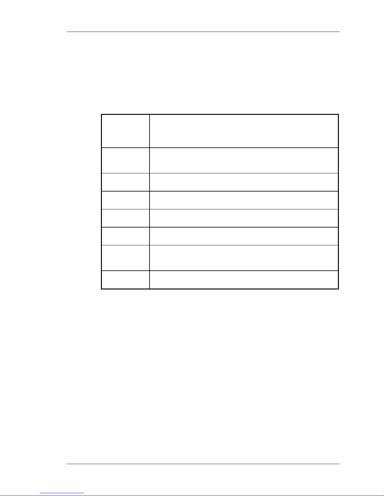
This manual is divided into five chapters and three appendices. The
main Table of Contents will help you to quickly locate the chapter that
contains the information you may be seeking. The following is a brief
description of each chapter.
Chapter 1
Chapter 2
Chapter 3
Chapter 4
Chapter 5
Appendix A
Appendix B
Appendix C
The chapter you are reading. This chapter provides information
on the content of the manual, the documentation conventions
used, safety considerations that need to be observed, and a
concise Getting Started Quickly section.
This chapter acquaints the user with the GMW-25 Plasma
Generator. It covers major features and front and rear panel
descriptions.
This chapter covers everything needed to install and set up your
generator from Unpacking and Inspection to Initial Power up.
This chapter covers in more detail how to operate your generator
and take advantage of all of its features.
This chapter details common troubleshooting situations and
solutions you may encounter when using your generator.
This appendix provides complete physical and electrical
characteristics of your generator.
This appendix provides a glossary of all the symbols used in this
manual and on the generator per UL, CSA, TUV, and CE
certifications.
This appendix provides a glossary of new terms that have been
used throughout this manual.
GMW-25 1-3
Introduction
1.1.2 Documentation Conventions
To better emphasize important information in this manual, the below
methods of formatting have been used to call attention to this
information.
Commands
Many parts of this manual refer to computer commands and data. It is
important to recognize the conventions used in this manual in order to
understand the meaning of these commands.
Angle Brackets
Rounded Brackets
Square Brackets
< >
( )
[ ]
These brackets are shown for command parameters.
They are not part of the command and should not be
entered.
These brackets contain hex-equivalent numbers for
printable or non-printable characters. The lower-case "h
(h) stands for hexadecimal.
These brackets indicate a symbol name for special
control codes or non-printable characters. Examples of
commonly used control codes are listed below.
[LF] Line Feed (0Ah)
[CR] Carriage Return (0Dh)
[ESC] Escape (1Bh)
Definitions
This icon is used to set off a definition of a new term used in this
manual. Appendix C provides a complete list of all the new terms used
here.
1-4 GMW-25
Introduction
1.2 Safety Considerations
Certain safety considerations must be observed before operation of
this generator can be attempted. Safety labels are used in both the
manual and on the generator to alert operating and service personnel
to conditions that may cause personal injury or damage to the
equipment from misuse or abuse. Please read the labels and
understand their meaning.
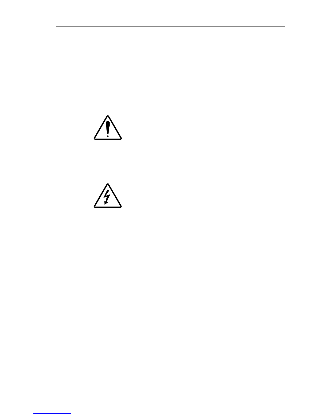
1.2.1 Operating and Maintenance Cautions
The caution label is used in this manual to caution the reader that
failure to follow important operating or maintenance instructions could
adversely affect equipment reliability.
1.2.2 Shock Hazard Warnings
The warning label is used in this manual to warn the reader of a
procedure or practice that could result in personal injury if not followed
carefully.
The lightning bolt within a triangle is used to alert operating and service
personnel to the presence of un-insulated voltage within the enclosure
of sufficient magnitude to cause dangerous electric shock. Only
authorized service personnel with a schematic diagram and knowledge
of the voltages existing within the equipment shall remove covers or
panels bearing this symbol.
GMW-25 1-5
Introduction
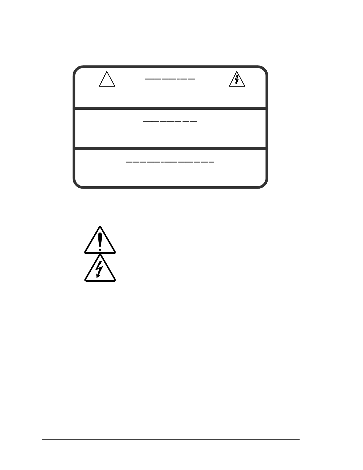
1.2.3 Service
!
-- SERVICE BY AUTHORIZED PERSONNEL ONLY
-- REFER TO INSTALLATION AND OPERATING INSTRU CTIONS
-- DISCONNECT POW ER FOR ANY SERV ICE WORK
-- SERVICE NUR VON FACHPERSONAL
-- INSTA LLATIONS - UND G EBRAUCHSANWEISUNG B EACHTEN
-- BEI SERVICE ARBEITEN VOM NETZ TRENNEN
-- CONFIER LA MAINTEN ANCE A` UNE PERSONNE QUALIFEE
-- CO NSULT ER LA NOTICE D'INS TALLA TION E T D'UTI LISATION
-- COUPER L' ALIMENTATION AVANT TOUTE MAINTENANCE
WARNING
WARNUNG
AVERTISSEMENT
Service Warning Marking
Figure 1.2.3
MKS, ENI Products is responsible for safety, reliability, and
performance of the equipment only if:
• Assembly operations, extensions, readjustments,
modifications, or repairs are carried out by authorized
personnel.
• The electrical installation is made in accordance with the
installation instructions provided and the room in which the
equipment is installed complies with the environmental
requirements.
• The equipment is used in accordance with the instructions
for use.
1-6 GMW-25
Introduction
1.2.4 Safety Labels
RF Radiation Warning Label
This label is used to caution the user that the unit produces RF
radiation that can be harmful.
Heavy Object Warning Label
This label is used to caution the user that the unit weighs over 35 lbs
(16 kg) and should be moved by two people.
1.2.5 Technical Support
On the back of the generator is a label with an "800" number for MKS,
ENI Products’ Technical Support. Should you have any difficulties with
your generator and have exhausted all possibilities in the
Troubleshooting Chapter, please feel free to call us.
1- 800- 724- ENI1 (3641)
TECHNI CAL SUPPORT
Technical Support Label
Figure 1.2.5
GMW-25 1-7
Introduction
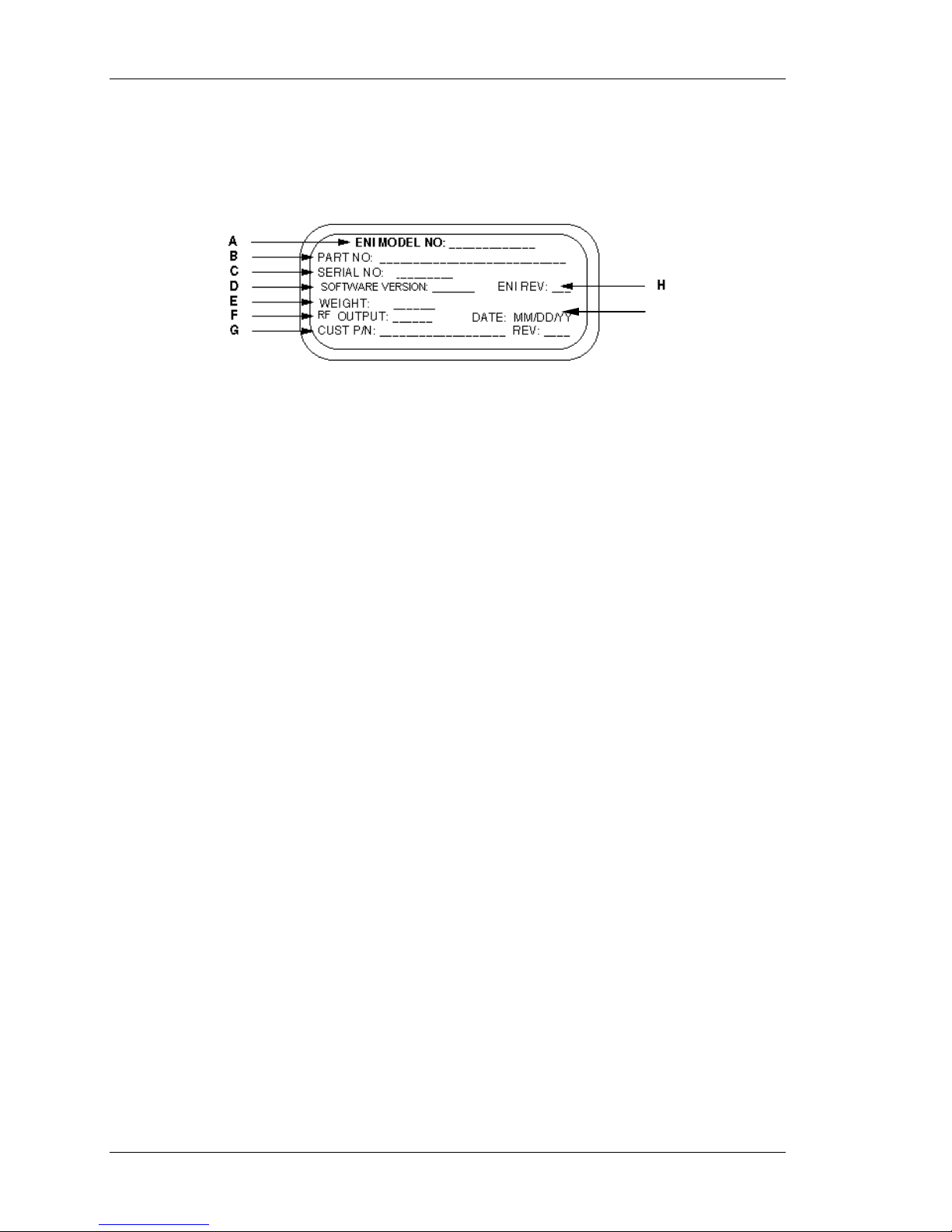
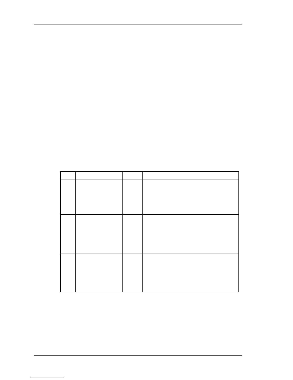
1.3 Nameplate
The GMW-25 Plasma Generator can be identified by a nameplate on
the back of the unit that contains the following information:
GMW-25 Serial Tag Label
A.
ENI MODEL NUMBER:
The model number that uniquely
identifies the unit.
B.
PART NO:
The assembly number that uniquely
identifies the product configuration.
(See section 1.4 for more information
on the model number.)
C.
SERIAL NO:
The number that is sequentially
assigned as the product is
manufactured.
D.
SOFTWARE VERSION:
The version number that identifies the
software configuration.
E.
WEIGHT:
The weight of the unit.
Figure 1.3
I
F.
RF OUTPUT:
The output of the unit in watts and its
operating frequency.
G.
CUST P/N:
A number that is specific to the
customer who ordered the unit and
that contains the customer's own part
number and revision level.
H.
ENI REV:
The revision letter that identifies the
product configuration. Revision A is
the initial revision level.
I.
DATE:
The date of manufacture in
MM/DD/YY format.
1-8 GMW-25

Introduction
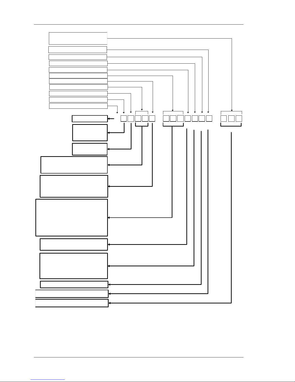
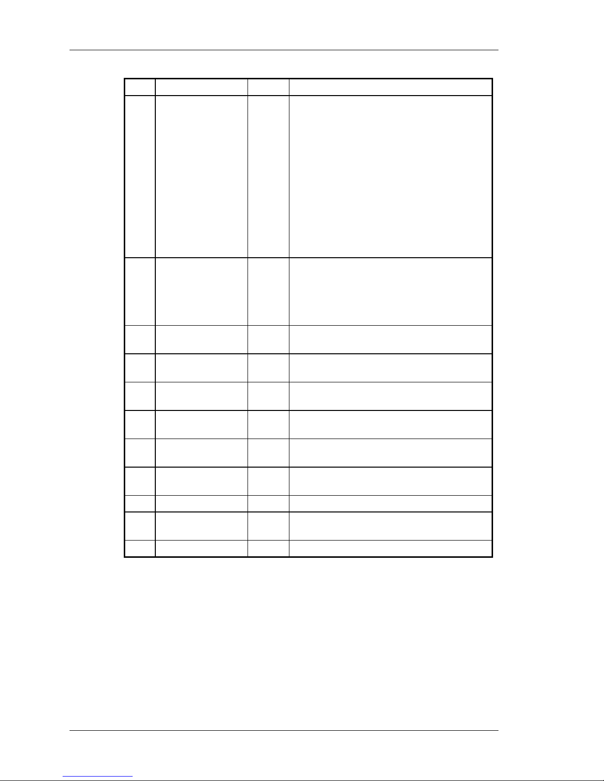
1.4 Generator Options at a glance
Before the unit is installed and powered up, it is important to ensure
that the correct unit was received. The model numbers of the Genesis
line of generators have been configured in such a way that it is easy to
tell what option has been installed on a specific unit. The number
generated from this matrix defines the configuration of that unit and
results in a part number that will be utilized throughout the
manufacturing process.
This matrix should be used to compare the configuration of the unit
that was initially ordered to the configuration of the unit received. If
they are different, contact the nearest MKS, ENI Products’ Sales or
Service location for assistance.
GMW-25 1-9
Introduction
Interface Card Configuration
For ENI Inte r nal Use Only
Blank
Output RF Connector
Front Panel Configuration
Frequency
AC Input Phase
Power
Cooling
Frequency Range
Product Series
G
L
M
H
W
A
1.25kW
12
2.5kW
25
5.0kW
50
Single Phase North American
X
3 Phase North American
A
Single Phase Europe
Y
3 Phase Europe
E
0.2MHz
D20
0.27MHz
D27
0.38MHz
D38
0.4MHz
D40
0.8MHz
D80
1.0MHz
1D0
2.0MHz
2D0
Blank
B
Full Featured
F
None
0
9 Pin PL2-HF Emulation
1
15 Pin Analog
2
25 Pin Analog Emulation
3
37 Pin Analog Emulation
4
70
1D
2D9
4D0
12D
13D
27D
40D
2.9MHz
4.0MHz
12.56MH
13.56MHz
27.12MHz
40.68MHz
GENESIS
LOW FREQ
MID FREQ
HIGH FREQ
Water
Air
7.0kW
10.0kW
G
-
-
N, H, C, L
Reserved for Future Use
For ENI Internal Use Only
Genesis Part Number Interpreter
1-10 GMW-25
Figure 1.4

Introduction
This part number interpreter is comprised of 18 separate fields. In
these fields, letters and numbers are used to define the final
configuration of a unit.
The unit you have received should have the value “25“ in the fourth
and fifth fields of the final part number. Check the serial tag on the
back of the generator. If it doesn’t have “25” in the part number,
contact the nearest MKS, ENI Products’ Sales or Service location for
assistance.
GMW-25 1-11
Introduction
1.5 Getting Started Quickly
This section is intended to provide you with a set of instructions to
enable you to quickly set up and start running your generator.
References to more detailed information are provided at the end of
each step.
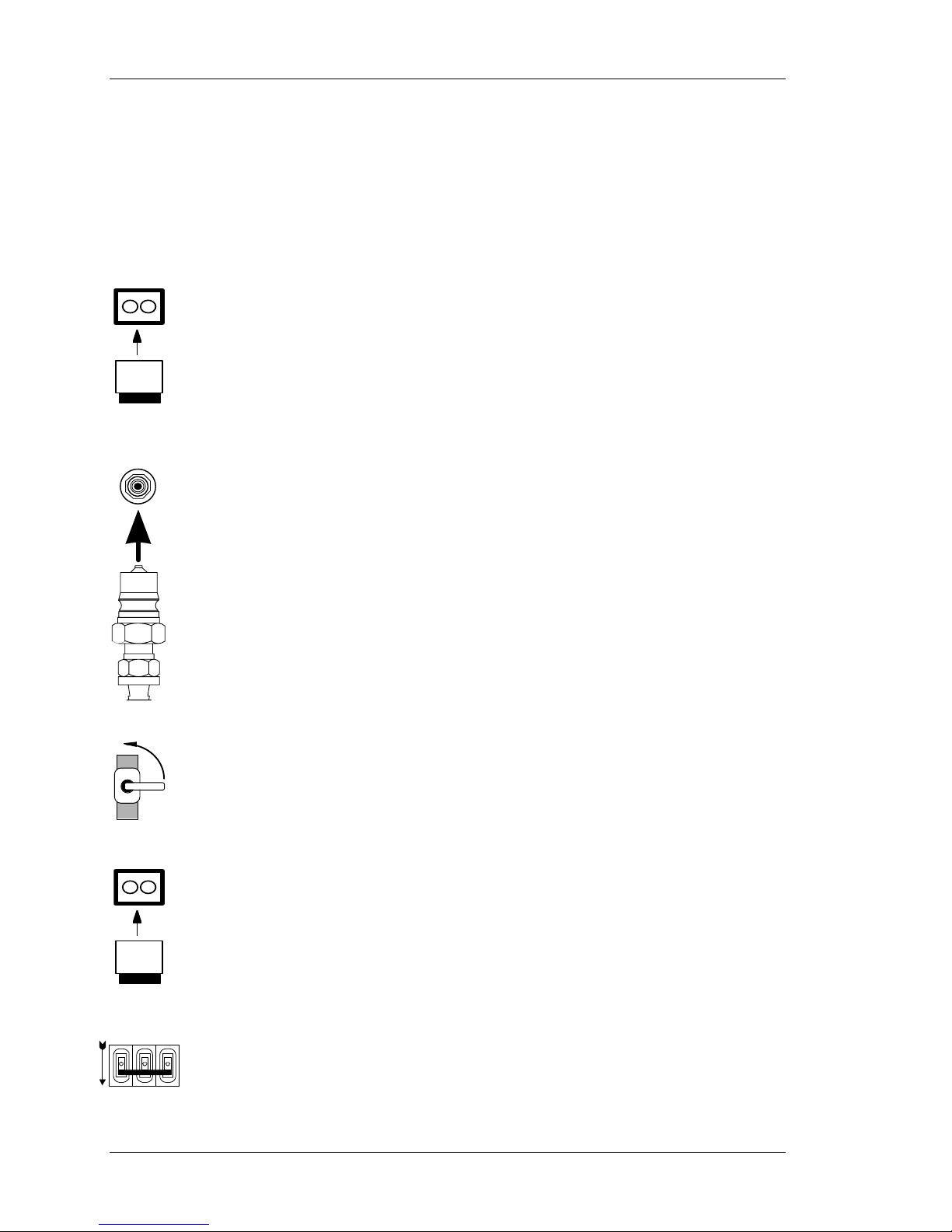
To quickly set up your GMW-25 generator, follow the procedure below:
1. Connect the solenoid valve plug.
(See section 2.10 for a description of the solenoid valve.)
2. Connect the water inlet and outlet hoses securely to the water
inlet and outlet connections on the rear panel of the generator.
(See section 2.10 for more information on the connectors.)
3. Once they are securely connected, turn both water valves to the
open position.
4. Insert the External Interlock plug into the interlock connector on
the rear panel marked “INTERLOCK.” AC Power will not engage
until this interlock is defeated (plugged).
(See section 2.7 for more information about the safety
interlocks.)
5. Make sure the AC Mains Circuit Breaker is in the OFF position
(The
O symbol should be showing).
1-12 GMW-25
Introduction
6. For units without a hard-wired line cord, plug the AC Main line
cord into the AC receptacle in the back of the unit. Make sure the
line voltage matches the voltage you selected when the unit was
ordered.
(See section 1.4 for the available line voltages and section 2.9
for more information on AC Power Requirements.)
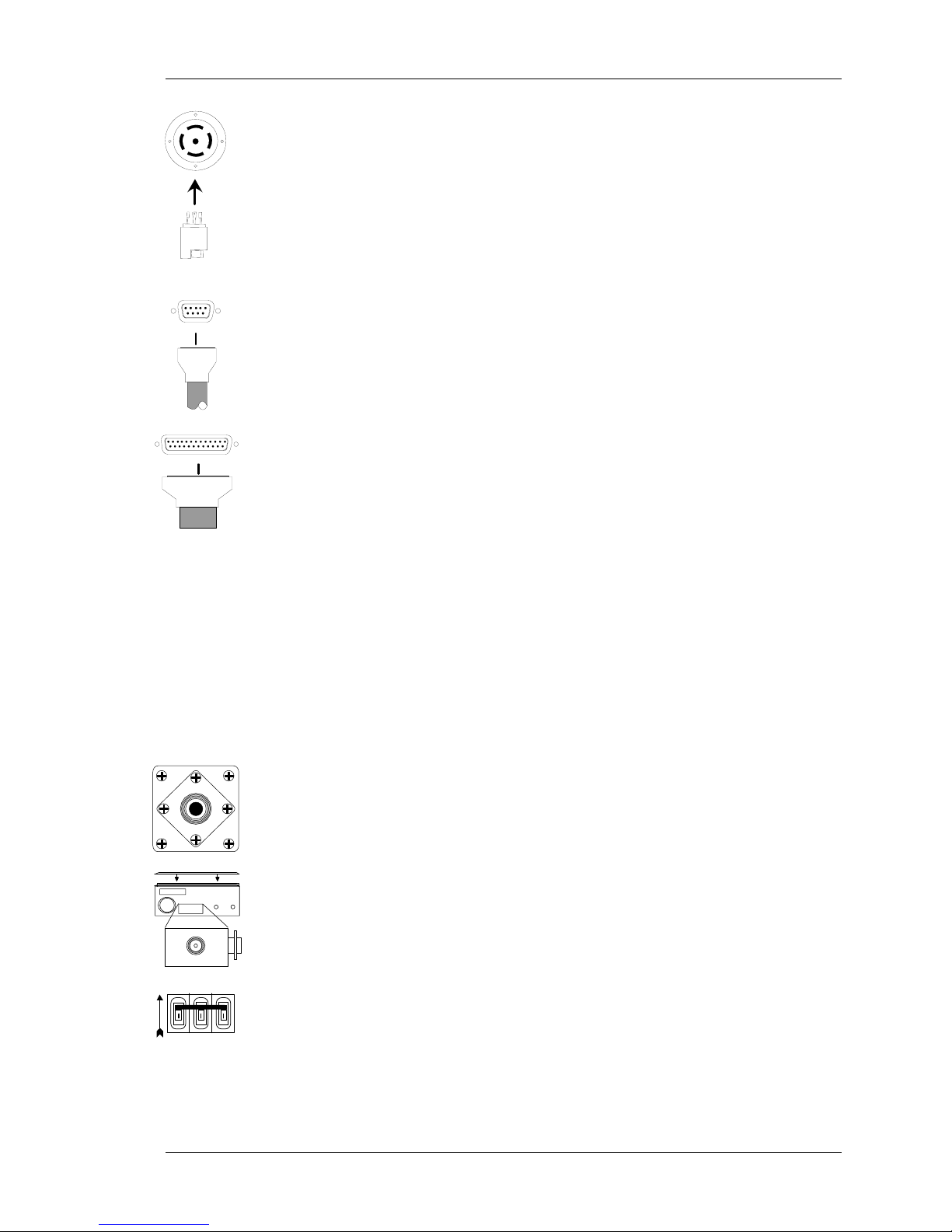
7. Connect the 9-pin male serial digital interface to the female serial
interface connector on the rear panel.
See Table 2.5.1 for pin outs.
8. Connect an analog control cable, if you’re not running a remote
front panel, to the analog interface connection on the rear panel.
There is a safety interlock in Pins 10 and 23. This interlock must
also be defeated (in this case shorted) for the unit to work (see
section 2.4 for Interlock Pin Outs). The AC power contactor will
not engage unless this interlock is defeated.
This interface will vary depending on what type of interface was
selected when the unit was ordered.
If your unit does not have a fully functional front panel or you are
using a remote front panel or a terminal, connect the interface
input. This connection is either a 9-pin, 15-pin, 25-pin, or 37-pin
plug. (See section 2.4 for analog interface types.)
9. Connect the load from the plasma chamber to the RF output
connection. This will vary depending upon the application you
are using.
10. Make sure that the unit covers and the RF output cover are on.
There are safety interlocks in all these locations that must be
engaged or the unit will not work. (See section 2.7 for more
information about the safety interlocks.)
11. Flip the AC mains switch up to the ON position (The
should be showing). You should hear the contactor engage. The
GMW-25 1-13
front panel display should appear like the following:
I symbol
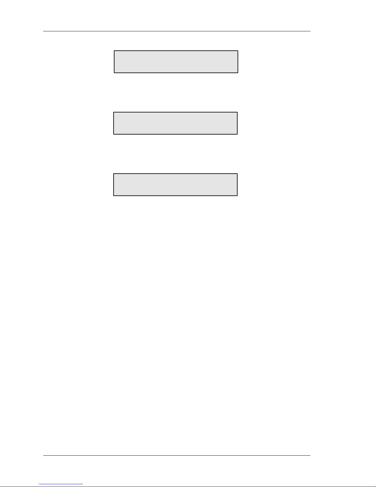
Introduction
AUX LEV MODE
REVFWD
ENI
Genesis Generator
SET POINT STATUS
The display will clear and show the following:
AUX LEV MODE
0 FP 0 0
REVFWD
0W NORMAL
or:
SET POINT STATUS
AUX LEV MODE
REVFWD
3W FP 3 1
46W 2000000 Hz
SET POINT STATUS
(This display is only shown on auto-tune generators)
12. From the terminal, you should see the following message:
Power up delay in effect-please wait
Then the terminal will show the following:
ENI monitor on
13. The generator is now ready to run RF.
1-14 GMW-25

System Installation
Chapter 2
System Installation
2.1 Unpacking/Inspection
2.1.1 Mechanical Inspection
If damage to the shipping carton is evident, request the carrier’s agent
be present when the unit is unpacked. Check for equipment damage
and inspect the cabinet and panels for dents and scratches.
2.1.2 Claim for Damage
Please notify MKS, ENI Products directly or your authorized MKS, ENI
Products’ representative if the product is mechanically damaged or
fails to meet specifications upon receipt. Retain our shipping carton
and packing material for the carrier's inspection, as well as for
subsequent use to return the unit should this become necessary.
2.1.3 Packaging for Reshipment
Whenever possible, the original shipping carton and packing material
should be used for reshipment. If the original packing material is not
available, wrap the instrument in heavy paper or plastic. Use a strong
shipping container. If a cardboard carton is used, it should be at least
200-lb. test material.
Use shock-absorbing material around all sides of the instrument to
provide a firm cushion and to prevent movement inside the container
wall on each side. Protect the front panel by means of cardboard
spacers inserted between the front panel and the shipping carton.
Make sure that the instrument cannot move in the container during
shipping. Seal the carton with a good grade of shipping tape and mark
the container: FRAGILE! ELECTRONIC INSTRUMENT
GMW-25 2-1
Drain water before shipment.
System Installation
2.2 Installation Requirements
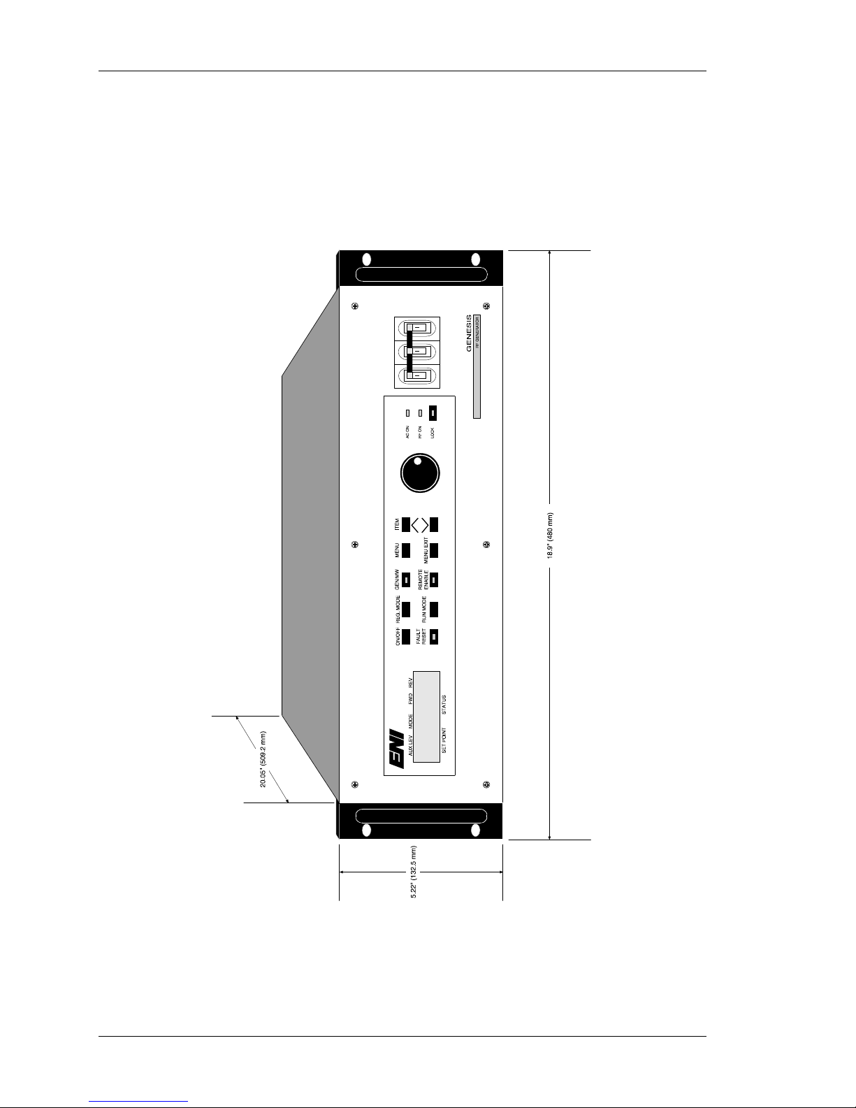
2.2.1 Dimension Requirements
The following figure shows the dimension requirements for standard
19-inch rack mountings.
Front & Side Dimension Requirements
w/ Fully Functional Front Panel
2-2 GMW-25
Figure 2.2.1
System Installation
2.3 Rack Installation
To ensure proper operation of the GMW-25, it is important to provide
correct mechanical support within a rack installation.
2.3.1 Installing into a Cabinet Assembly
The GMW-25 generator can be installed in a cabinet assembly. The
procedures for this depend upon the type of cabinet used. At the time
the unit was ordered, the cabinet type was specified. Information is
given below on installing the unit into the most common cabinet
assembly.
19-inch Cabinet
The front panel can be ordered with a hole pattern for mounting in a
19" EIA rack. However, the generator must be supported on a rack
shelf since the front panel is not strong enough to support the weight of
the generator. Ground braid must be connected from the generator
ground stud to the chassis ground on the cabinet.
Because of the weight of the generator, extreme caution
should be used during installation. Steps should be taken
to ensure that the rack will not tip when the unit is
extended out of the rack.
GMW-25 2-3
System Installation
2.4 System Interconnect
The GMW-25 generator is available with four options for the analog
interface:
• No interface card
• 25-pin analog
• 37-pin analog emulation
• 9-pin emulation for ENI’s PL-2HF generator
In order to maintain EMC compliance, I/O cables should be
constructed using shielded cable (Alpha Supra-Shield or equivalent)
and metallized backshells providing 360° shield termination.
Each of these options is described in detail below and the appropriate
pin out table is also given.
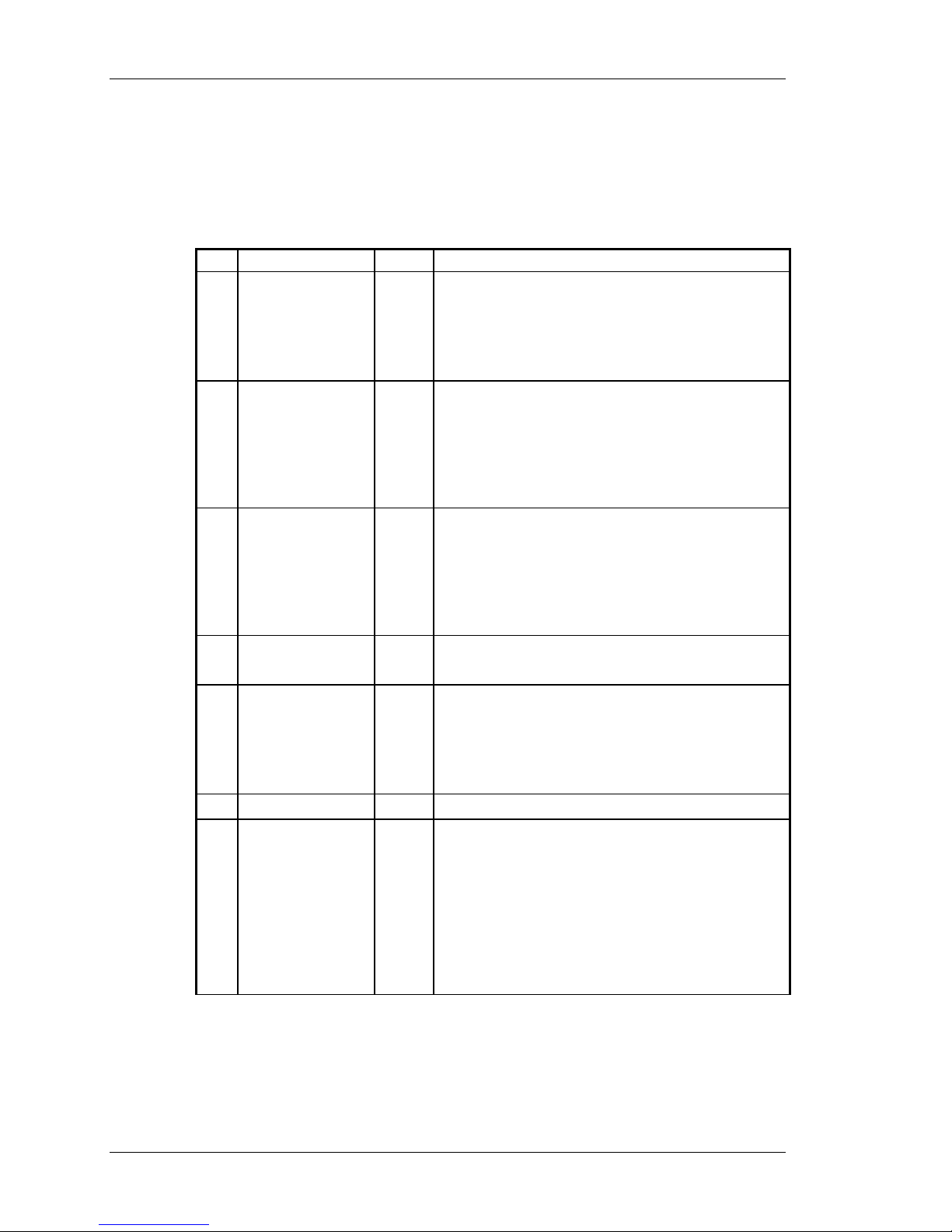
2.4.1 Standard 25-pin Analog I/O Interface (ENI P/N: 1050-235)
The analog I/O Interface for the GMW-25 generator provides:
Pin Name Type Description
1
2
3
DI = Digital Input DO = Digital Output AI = Analog
Max. Power (E) DO Emitter side of isolated transistor switch.
(See Note 1)
Transistor ON - Indicates a max. reverse
power or max. current fault.
Transistor OFF - No fault.
Reflected power (+) AO A linear DC voltage that represents the
reflected power output level.
0 V = 0 W and the max. value is adjustable
between 0 and 12 VDC. Typically
calibrated to 10 VDC = Maximum Reflected
Power Limit.
Forward power (+) AO A linear DC voltage that represents the
forward power output level.
0 V = 0 W and the max. value is adjustable
between 0 and 12 VDC. Typically
calibrated to 10 VDC = Maximum Rated
Power.
AO = Analog Output
Input
25-pin Analog I/O Interface Pin Outs
2-4 GMW-25
Table 2.4.1

System Installation
Pin Name Type Description
4
5
6
7
8
9
10
DI = Digital Input DO = Digital Output AI = Analog Input AO = Analog Output
RF ON/OFF
Control (+)
Power set point (+) AI A linear DC voltage to set the output power
+28 VDC User voltage for interface purposes. Rated
RF ON (E) DO Emitter side of isolated transistor switch.
Analog remote
enable
Overheat (E) DO Emitter side of isolated transistor switch.
Interlock This pin should connect to Pin 23 to
DI A voltage between this and Pin 17 will turn
RF power ON.
Leaving it open or applying zero voltage will
turn RF power OFF.
The nominal voltage to turn RF ON is
selectable between +5 V or +24 V via a
jumper on the control board, however it
should not exceed 30 VDC.
level.
0 V = 0 W and the max. value is adjustable
between 0 and 12 VDC. Input impedance is
100 k ohms balanced differential to ground.
50 mA max.
(See Note 1)
Transistor ON - RF ON.
Transistor OFF - RF OFF.
DI Ground referenced logic input. (See Note 2)
LOW - Selects analog remote control mode.
HIGH - Disables analog remote control
mode.
Leaving this pin disconnected will ensure a
configurable HIGH or LOW state (Rev. A
Interface only).
Note: If the generator is in digital remote
mode, it cannot switch to analog remote
mode until the digital remote mode is
disabled. Therefore, setting this pin low will
have no effect until the digital remote mode
is disabled.
(See Note 1)
Transistor ON - Overheat fault.
Transistor OFF - No fault.
complete the interlock chain.
If the interlock chain is broken, the AC
contactor will open. External circuit should
be capable of switching 100 mA at 24 VAC.
25-pin Analog I/O Interface Pin Outs (Cont’d)
GMW-25 2-5
Table 2.4.1
System Installation
Pin Name Type Description
11
12
13
14
15
16
17
18
19
20
21
Leveling select DI Ground referenced logic input. (See Note 2)
LOW - Selects forward-power leveling.
HIGH - Selects an alternative power-leveling
mode.
Leaving this pin disconnected will ensure a
configurable HIGH or LOW state.
Note: The alternate power-leveling mode is
selected via a software switch in a
CALIBRATION menu. Either load-power
leveling or an external source such as DC
Bias may be selected. The default is Load
Power Leveling.
Load power (+) AO A linear DC voltage that represents the load
power output level.
0 V = 0 W and the max. value is adjustable
between 0 and 12 VDC. Typically calibrated
to 10 VDC = Maximum Rated Power.
+15 VDC User voltage for interface purposes. Rated
10 mA max.
Max. power (C) DO Collector side of isolated transistor switch
for Pin 1.
Reflected power
return (-)
Forward power
return (-)
RF ON/OFF
Control (-)
Power set point
return (-)
GND Signal / Chassis ground.
RF ON (C) DO Collector side of isolated transistor switch
GND Signal / Chassis ground.
AO Signal return for Pin 2.
AO Signal return for Pin 3.
DI Signal return for Pin 4.
AI Signal return for Pin 5.
for Pin 7.
25-pin Analog I/O Interface Pin Outs (continued)
2-6 GMW-25
Table 2.4.1

System Installation
Pin Name Type Description
22
23
24
25
DI = Digital Input DO = Digital Output AI = Analog Input AO = Analog Output
Note 1: For all isolated transistor outputs.
Transistor OFF (switch open) - VCEmax = 40 VDC (IC < 500 µA)
Transistor ON (switch closed) - ICmax = 10 mA (VCE < 1 V)
Overheat (C) DO Collector side of isolated transistor switch
for Pin 9.
Interlock This pin should connect to Pin 10 to
complete the interlock chain.
If the interlock chain is broken, the AC
contactor will open.
Option V User voltage for interface purposes. This
voltage is configurable for
+5 VDC or -15 VDC via a jumper on the
control board. Rated 10 mA max.
Load power return
(-)
AO Signal return for Pin 12
Note 2: For all ground referenced logic level inputs.
HIGH = 2 VDC min. to 30 VDC max.
LOW = -0.2 VDC min. to 1 VDC max.
25-pin Analog I/O Interface Pin Outs (continued)
Table 2.4.1
GMW-25 2-7
System Installation
2.4.2 37-pin Analog I/O Interface (ENI P/N: 1050-295)
The 37-pin Analog I/O Interface is optically insulated from the
generator at the interface board interconnect point. Therefore, to use
this interface card, the customer system needs to source power to the
interface board on Pins 36 and 37.
Pin Name Type Description
MAX POWER (E) DO Emitter side of isolated transistor switch. (See
1
Note 1)
Transistor ON - Indicates a max. reverse power
or max. current limit.
Transistor OFF - No limit reached.
2
3
4
5
6
7
DI = Digital Input DO = Digital Output AI = Analog Input AO = Analog Output
REFLECTED
POWER (+)
FORWARD
POWER (+)
RF ON/OFF
RETURN
POWER
SETPOINT (+)
No Connect N/A NONE
GENERATOR
READY (E)
AO A linear DC voltage that represents the reflected
power output level.
0 V = 0 W and the max. value is adjustable
between 0 and 12 VDC.
Typically calibrated to 10 VDC = Maximum
Reflected Power Limit.
AO A linear DC voltage that represents the forward
power output level.
0 V = 0 W and the max. value is adjustable
between 0 and 12 VDC.
Typically calibrated to 10 VDC = Maximum Rated
Power.
DI Signal return for Pin 29.
AI A linear DC voltage to set the output power level.
0 V = 0 W and the max. value is adjustable
between 0 and 12 VDC.
Input impedance is 100 k ohms balanced
differential to ground.
DO Emitter side of isolated transistor switch. (See
Note 1)
Transistor ON - GENERATOR READY
Transistor OFF - GENERATOR NOT READY
Signal Definition:
Generator Ready = interlock chain complete (see
Pins 10 & 35) as well as no present generator
overheat condition.
2-8 GMW-25
37-pin Analog I/O Interface
Table 2.4.2
 Loading...