

MKS CDN466, CDN467 User Manual

ToolLink DeviceNet Gateway
Control & Information Technology Group
3350 Scott Blvd Bldg 4
Santa Clara CA 95054
Main: 408.235.7620
Fax: 408.235.7625
User Manual
Rev. 01
01/04

ToolLink User Manual
TABLE OF CONTENTS
CHAPTER 1 – OVERVIEW.......................................................................................................................................4
HARDWARE ...............................................................................................................................................................4
CONFIGURATION .................................................................................................................................................6
DEVICENET INTERFACE.............................................................................................................................................6
SERIAL INTERFACE....................................................................................................................................................7
CHAPTER 2 – QUICK START GUIDE...................................................................................................................8
HARDWARE SETUP ....................................................................................................................................................8
SYSTEM CONFIGURATION..........................................................................................................................................8
CONFIGURING THE GATEWAY ...................................................................................................................................8
TRANSFERRING DATA................................................................................................................................................9
CHAPTER 3 – THEORY OF OPERATION..........................................................................................................10
DEVICENET INTERFACE...........................................................................................................................................10
SERIAL INTERFACE..................................................................................................................................................11
CHAPTER 4 – GATEWAY CONFIGURATION...................................................................................................13
CONFIGURE DEVICENET INTERFACE .......................................................................................................................13
DeviceNet Baud Rate Switch..............................................................................................................................13
MAC ID Switches...............................................................................................................................................13
POWER UP GATEWAY..............................................................................................................................................13
DeviceNet Status LEDs......................................................................................................................................13
Serial Channel Status LEDs...............................................................................................................................14
Register EDS File ..............................................................................................................................................14
CHAPTER 5 – DEVICENET PROFILE.................................................................................................................15
DeviceNet Message Types..................................................................................................................................15
DEVICENET OBJECT CLASSES .................................................................................................................................15
IDENTITY OBJECT CLASS CODE: 01 (0X01).........................................................................................................15
Revision – Attribute 4.........................................................................................................................................16
Device Status – Attribute 5.................................................................................................................................16
Serial Number – Attribute 6...............................................................................................................................16
ROUTER OBJECT CLASS CODE: 02 (0X02).........................................................................................................17
DEVICENET OBJECT CLASS CODE: 03 (0X03) .....................................................................................................17
MACID – Attribute 1..........................................................................................................................................18
Baud Rate – Attribute 2......................................................................................................................................18
Allocation Information – Attribute 5..................................................................................................................18
ASSEMBLY OBJECT CLASS CODE: 04 (0X04).......................................................................................................18
CONNECTION OBJECT CLASS CODE: 05 (0X05)...................................................................................................19
State – Attribute 1 ..............................................................................................................................................20
Connection ID’s – Attributes 4 and 5 ................................................................................................................20
Production and Consumed Sizes – Attributes 7 and 8.......................................................................................21
Watch Dog Timeout Activity – Attribute 12.......................................................................................................21
USER DEFINED (SERIAL STREAM) OBJECT CLASS CODE: 100 (0X64)..................................................................21
Receive Data – Attribute 3.................................................................................................................................22
Transmit Data – Attribute 4...............................................................................................................................22
Baud Rate – Attribute 6......................................................................................................................................23
Parity – Attribute 7 ............................................................................................................................................23
Flow Control – Attribute 8.................................................................................................................................23
Receive Mode – Attribute 9................................................................................................................................23
Time-Out:...........................................................................................................................................................24
Start/Stop Delimiters: ........................................................................................................................................24
Stop Delimiter:...................................................................................................................................................24
MKS Instruments, Inc. Page 2 of 30

ToolLink User Manual
Start Delimiter:..................................................................................................................................................24
No Delimiters:....................................................................................................................................................25
Start Delimiter String – Attribute 9....................................................................................................................25
Stop Delimiter String – Attribute 10 ..................................................................................................................25
Rx Handshake Enable – Attribute 11.................................................................................................................25
TX Handshake Enable – Attribute 11.................................................................................................................26
Maximum Rx Size – Attribute 19........................................................................................................................26
Maximum TX Size – Attribute 20.......................................................................................................................26
Byte Swapping – Attribute 21.............................................................................................................................27
APPENDIX A – PRODUCT SPECIFICATIONS..................................................................................................28
DEVICENET INTERFACE...........................................................................................................................................28
SERIAL CHANNEL....................................................................................................................................................28
ENVIRONMENTAL....................................................................................................................................................28
APPENDIX B – ASCII CHARACTER CODES ....................................................................................................29
MKS Instruments, Inc. Page 3 of 30
ToolLink User Manual
Chapter 1 – Overview
This document describes how to install, configure, and operate the CDN46X series of serial to DeviceNet
gateways. The following products are covered in this user manual:
Part Number FW Rev. Serial Channel
CDN466 1.01 or higher RS232 full duplex
CDN467 1.01 or higher RS485 half duplex
The CDN46X gateways allow you to easily interface a wide variety of serial devices to any DeviceNet
industrial control network. Standard CDN46X products are tightly packaged and sealed in a rugged
industrial case. Board-level and customized gateways are also available upon request
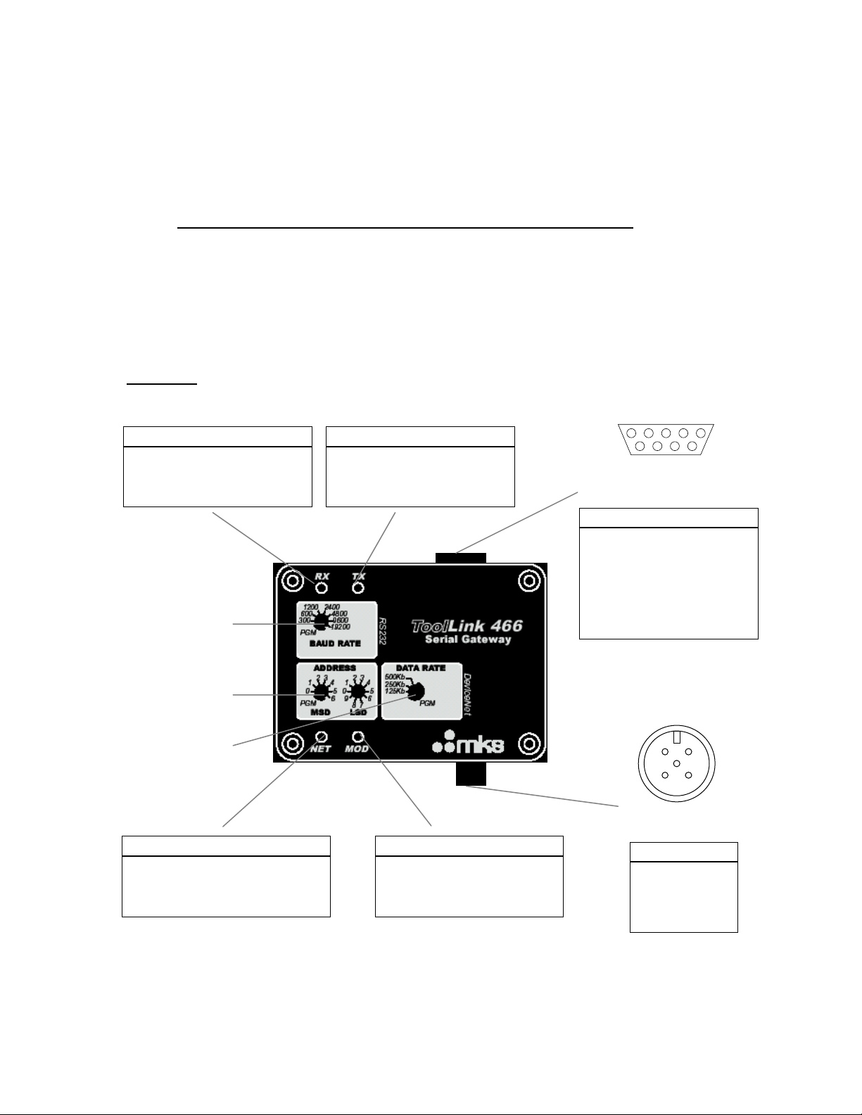
Hardware
Receive Status LED (RX)
STATE DESCRIPTION
OFF Not receiving data
RED BLINK Not defined
RED Receive error
GREEN BLINK Receiving data
GREEN Not defined
Serial Baud Rate
Rotary Switch
DeviceNet Address
Rotary Switches
Transmit Status LED (TX)
STATE DESCRIPTION
OFF Not transmitting data
RED BLINK Not defined
RED Transmit error
GREEN BLINK Transmitting data
GREEN Not defined
PIN CDN466 CDN467
1 nc RS485A (+)
2 RXD RS485B (-)
3 TXD 120Ω TR**
4 DTR/DSR* nc
5 SGND nc
6 DTR/DSR* nc
7 RTS nc
8 CTS nc
9 nc nc
*Pins 4 and 6 connected internally.
**Connect pins 2 & 3 to terminate RS485
with 120Ω resistor.
.
1
Isolated Serial Channel
(male DB9 connector)
52 3 4
96 7 8
DeviceNet Data Rate
Rotary Switch
DeviceNet Status LED (NET)
STATE DESCRIPTION
OFF No power
RED BLINK Configuration error
RED Unrecoverable error
GREEN BLINK Not allocated to a master
GREEN Allocated to a master
Module Status LED (MOD)
STATE DESCRIPTION
OFF No power
RED BLINK Configuration error
RED Unrecoverable error
GREEN BLINK Not defined
GREEN Normal operation
DeviceNet Channel
(male 5-pin micro connector)
PIN SIGNAL
1 SHIELD
2 V+
3 V 4 CAN H
5 CAN L
5
3 4
1 2
MKS Instruments, Inc. Page 4 of 30
ToolLink User Manual
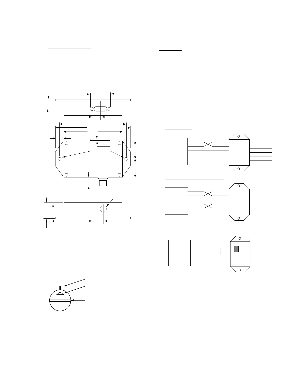
INSTALLATION
Mount the ToolLink Gateway on a horizontal or vertical
surface, in a suitable location or enclosure for your
application. Provide sufficient clearance and airflow to
maintain 0°C to 70°C ambient operating temperature
range. Fasten the ToolLink Gateway to the mounting
surface using two screws (not provided) in the 0.19 inch
0.65 0.45
All dimensions are inches
3.80
4.30
3.30
0.50
Mtg. Holes 1.225
(2) 0.19 DIA .
0.12
1.25
1.225
WIRING
The ToolLink Gateway requires two connections – one to the
DeviceNet network (male 5-pin micro connector) and one to the
serial device (male DB9 connector). DeviceNet and serial cables
are available from a variety of industrial sources. Follow all
applicable electrical codes in your area when mounting and wiring
any electrical device.
All power is received from the DeviceNet network. The ToolLink
Gateway draws up to 200mA from the 24VDC power supply.
Select your DeviceNet cables and power supply so that it can
provide sufficient current for all networked devices at their peak
operating power.
The following are typical ToolLink Gateway wiring examples. Your
RS232 or RS485 interface may vary. Refer to your device’s
documentation for the required data and control signals.
RS232 Interface
2
RXD
2
TXD
RS232
3
GND
5
Serial
Device
RS232 Interface, HW Flow Control
RXD
TXD
GND
3
5
CDN466
1
2
3
4
5
DRAIN
VDC+
VDCCAN H
CAN L
0.542
1.10
0.725
0.625 DIA. On Case Wall
0.70
ROTARY SWITCHES
Set the ToolLink rotary switches to the desired settings. Use
a small slotted screwdriver to rotate the switches. Align the
indicator arrow to the desired setting, as shown below.
switch position
switch indicator arrow
switch screw slot
Each rotary switch parameter has a PGM option. Setting a
switch to PGM allows the parameter to be remotely set over
DeviceNet. However, it must first be initialized. To initialize,
set the switch to desired value and power up the gateway.
The new settings are saved in its memory. Power down and
change switch to PGM mode.
2
RS232
3
5
Serial
Device
RS485 Interface
RS485
Serial
Device
RXD
TXD
GND
RTS
CTS78
DATAA
DATAB
Connect pins 2 & 3
to terminate cable
RXD
TXD
GND
CTS
DATAA
DATAB
TR
2
3
5
78RTS
1
2
3
CDN466
120
CDN467
1
2
3
4
5
1
2
3
4
5
DRAIN
VDC+
VDCCAN H
CAN L
DRAIN
VDC+
VDCCAN H
CAN L
MKS Instruments, Inc. Page 5 of 30

ToolLink User Manual
CONFIGURATION
Rotary switches and software parameters configure the ToolLink Gateway’s DeviceNet Interface, Serial
Interface, Serial Receive, and Serial Synchronization functions. The ToolLink Gateway can be configured
over its DeviceNet channel. Use your DeviceNet Configuration application program and the ToolLin k
EDS file to set the software parameters over the DeviceNet channel.
FUNCTION PARAMETER TYPE VALUE DESCRIPTION
DeviceNet
Interface
Data Rate Switch 0 = 125Kbps
Maximum Receive Size Software 0 to 64 bytes Defines the maximum receive message packet size. The total
Maximum Transmit Size Software 0 to 64 bytes Defines the maximum transmit message packet size. The total
Byte-Swap Enable Software 0 = disabled
Serial Interface Baud Rate Switch 0 = 300 4 = 4800
Parity Software 0 = No parity
Flow Control Software 0 = None
Serial Receive Receive Mode Software 0 = Timeout
Start Delimiter String Software String of 0-4 bytes:
Stop Delimiter String Software String of 0 to 4 bytes:
Serial
Synchronization
TX Handshake Enable Software 0 = disabled
Address Switch
RX Handshake Enable Software 0 = disabled
00 TO 63 Sets DeviceNet node address. MSD switch sets the most
1 = 250kbps
2 = 500Kbps
1 = enabled
1 = 600 5 = 9600
2 = 1200 6 = 19200
3 = 2400
1 = Even parity
2 = Odd parity
1 = XON/XOFF
2 = CTS/RTS
1 = Length
2 = Delimiter
[Length][B1][B2][B3][B4]
[Length][B1][B2][B3][B4]
1 = enabled
1 = enabled
significant digit (0x to 6x). LSD switch sets the least significant
digit (x0 to x9).
Sets DeviceNet data rate.
number of ToolLink input bytes is Maximum Receive Size + 4.
number of ToolLink output bytes is Maximum Transmit Size + 4.
Defines how ToolLink formats its input and output data fields.
When enabled, ToolLink swaps every 2 bytes in the data field.
Sets the serial channel baud rate.
Sets the serial channel parity mode. Received byte is tested for
errors, and then parity bit is cleared before the byte is saved in
RX buffer.
Sets the serial channel flow control.
XON/XOFF is a software flow control. Receiving device sends
XOFF when its buffer is full, suspending further transmissions
until it sends XON, indicating it is ready to again receive data.
XON and XOFF bytes are not saved as message data.
CTS/RTS is an RS232 hardware flow control option (CDN466
only). Gateway keeps RTS output active (low) when it can
receive data. Gateway only transmits data when CTS input is
active (low)
Selects how the gateway receives a complete message packet.
Used when Receive Mode = Start/Stop Delimiter.
Defines the start of a received message packet.
Used when Received Mode = Start/Stop Delimiter.
Defines the end of a received message packet.
Optional receive serial message handshake protocol between
ToolLink Gateway and application program.
Optional transmit serial message handshake protocol between
ToolLink Gateway and application program.
DeviceNet Interface
The ToolLink Gateway can receive serial message packets up to 68 bytes long. The DeviceNet Output
Size (Produce Size) is equal to the Maximum Receive Size + 4 bytes of overhead. The Maximum
Receive Size parameter defines the Data Field size (M) for the input bytes.
The ToolLink Gateway can transmit serial message packets up to 68 bytes long. The DeviceNet Input
Size (Consume Size) is equal to the Maximum Transmit Size + 4 bytes of overhead. The Maximum
Transmit Size parameter defines the Data Field size (N) for the output bytes.
MKS Instruments, Inc. Page 6 of 30
ToolLink DeviceNet Input Bytes
STATUS RXCTR TXACK LENGTH
1 byte 1 byte 1 byte 1 byte M bytes
ToolLink DeviceNet Output Bytes
COMMAND RXACK TXCTR LENGTH
1 byte 1 byte 1 byte 1 byte N bytes
DATA FIELD
DATA FIELD

ToolLink User Manual
Serial Interface
The Receive Mode parameter defines how the ToolLink Gateway receives serial message packets. The
three supported modes include Timeout mode, Length mode and Delimiter mode.
When in Timeout mode, the ToolLink Gateway waits for an inter-byte delay to signal the end of a
message packet. If the receiver is idle for more than 3.5 byte times (or 5 msec, whichever value is
greater), then all bytes received before the timeout are grouped into a single message packet. 1 byte
time = 10 bits ÷ baud rate.
When in Length mode, the ToolLink Gateway receives a fixed number of bytes as a complete message
packet. The Maximum Receive Size parameter defines the message packet size (0 to 64 bytes) for the
LENGTH mode.
When in delimiter mode, the ToolLink Gateway uses start and stop delimiter strings to identify the
beginning and end of a message packet. The Start Delimiter String parameter defines the beginning of
a message, and the Stop Delimiter String parameter defines the end of a message.
MKS Instruments, Inc. Page 7 of 30
ToolLink User Manual
Chapter 2 – Quick Start Guide
This chapter describes the setup for a simple gateway solution using a DeviceNet master and the serial
port of a PC using HyperTerminal. Before beginning a basic understanding of DeviceNet and rs232 is
required. Experience using explicit and poll transactions from the software provided with your DeviceNet
master is essential. For more information on generating explicit and poll messages consult the DeviceNet
master’s software user’s guide.
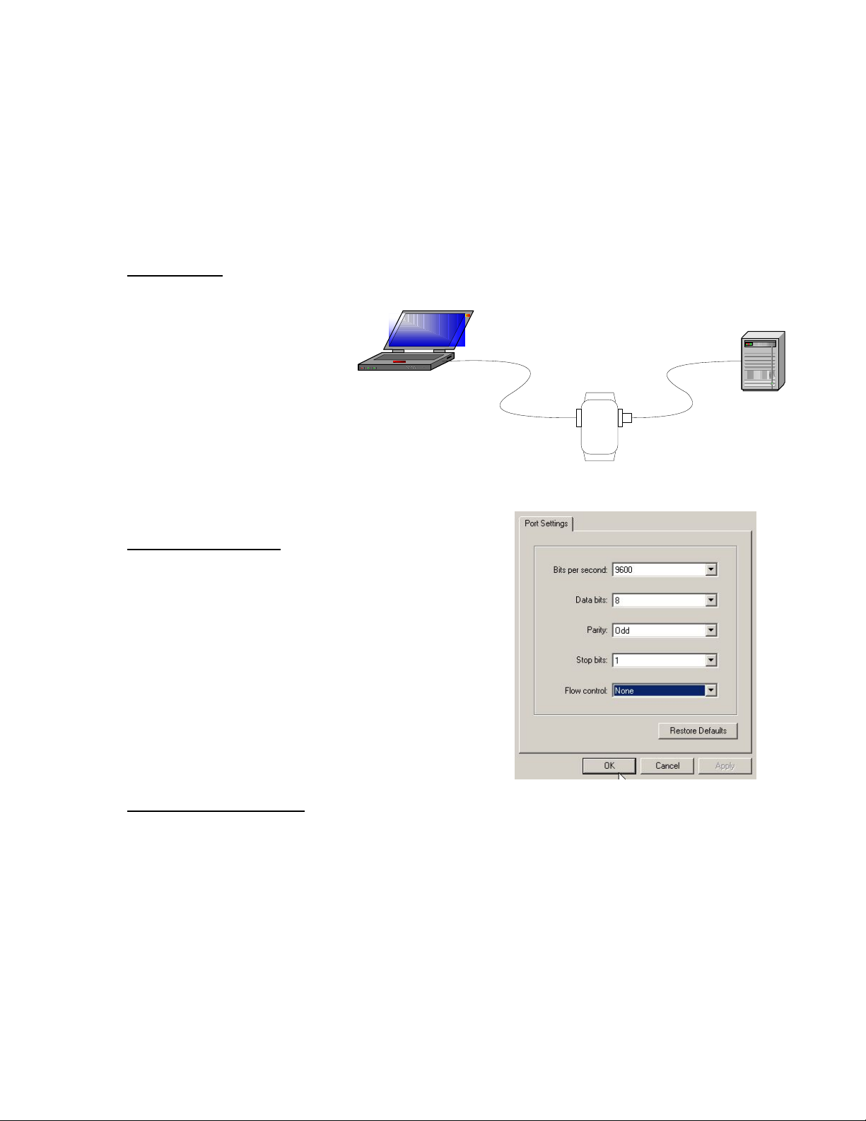
Hardware Setup
Setup a gateway connection between a device net master and the serial port of a PC.
Required Hardware:
• Null modem cable
• Device net cable
Com Port 1
• Device net master
• PC with HyperTerminal
• Serial gateway
Null Modem
Cable
CDN466/CDN467
System Configuration
Configure the HyperTerminal properties in the File Menu of
HyperTerminal with the following parameters.
• 9600 baud
• 1 stop bit
• 8 bits of data
• Odd parity
• No flow control
DeviceNet
Cable
DeviceNet
Master
Configuring the Gateway
The major steps for configuring the gateway include setting up the Serial Stream Object, the Serial
Receive Object, and the Serial Transmit Object. This example is for the CDN466. For
Configure the gateway switches as follows:
• MACID MSD to 0
• MACID LSD to 1
• DeviceNet Data rate to 500
• RS2323 baud rate to 9600
Once all of the hardware is setup and powered up, make sure that the master can allocate both poll and
explicit connections to the gateway. Once allocated, both the net and mod LED will be solid green.
MKS Instruments, Inc. Page 8 of 30

ToolLink User Manual
Using the DeviceNet master’s software loads the parameters for the serial stream object, the serial
receive object, and the serial transmit object in the tables below for the gateway through the device net
connection by using explicit messaging.
Table 1 Configure the serial stream object class 100 (0x64)
Attribute Access Name Value
6 Get/Set Baud Rate 9600
7 Get/Set Parity None
8 Get/Set Flow Control None
9 Get Receive Mode Timeout
13 Get/Set RX Handshake Enable 0 = No
16 Get/Set TX Handshake Enable 0 = No
19 Get/Set Max Receive Size 1
20 Get/Set Max Transmit Size 1
Transferring data
The ToolLink Gateway is now set up the receive data. The Output Size (Produce Size) will be equal to 5.
The 5 Byte poll response will is described below
The ToolLink Gateway is now set up the Transmit data. The Input Size (Consume Size) will be equal to
5. The 5 Byte poll will is described below.
ToolLink DeviceNet Input Bytes
STATUS RXCTR TXACK LENGTH
1 byte 1 byte 1 byte 1 byte 1 byte
ToolLink DeviceNet Output Bytes
COMMAND RXACK TXCTR LENGTH
1 byte 1 byte 1 byte 1 byte 1 byte
DATA FIELD
DATA FIELD
MKS Instruments, Inc. Page 9 of 30
 Loading...