

MKS AX346 Operating Instructions Manual
control – motion – interface
AX 346
Versatile Process Indicator
With Two Analogue Inputs and
Adjustable Analogue Output
• Two analogue inputs, each +/- 10V oder 0/4 – 20 mA with individual scaling
• Operation modes to display input A, input B or combined values A+B, A-B, AxB and A:B
• Selectable linearisation function with 16 interpolation points
• Adjustable analogue output, +/-10 V or 0/4 – 20 mA, proportional to the display
• Power supply 115/230 VAC and 17 – 30 VDC in one unit
• Auxiliary output 24 VDC / 100 mA for sensor supply
Operating Instructions
Ax34601a_e_A5.doc / Feb-06 Page 1 / 20

Safety Instructions
• This manual is an essential part of the unit and contains important hints about
function, correct handling and commissioning. Non-observance can result in
damage to the unit or the machine, or even in injury to persons using the
equipment !
• The unit must only be installed, connected and activated by a qualified electrician
• It is a must to observe all general and also all country-specific and application-
specific safety standards
• When this unit is used with applications where failure or maloperation could cause
damage to a machine or hazard to the operating staff, it is indispensible to meet
effective precautions in order to avoid such consequences
• Regarding installation, wiring, environmental conditions, screening of cables and
earthing, you must follow the general standards of industrial automation industy
• - Errors and omissions excepted –
Version: Description:
AX34601a_e_A5/Feb06/HK/KK Original edition
Ax34601a_e_A5.doc / Feb-06 Page 2 / 20

Table of contents
1. Introduction....................................................................................................4
2. Electrical Connections....................................................................................5
2.1. Power Supply .............................................................................................................. 5
2.2. Auxiliary Power Output ............................................................................................... 5
2.3. Analogue Inputs A and B ............................................................................................6
2.4. Adjustable Analogue Output.......................................................................................6
2.5. GND Potential Considerations ....................................................................................6
3. Configuration of the Analogue Inputs............................................................ 7
4. How to Operate the Front Keys...................................................................... 9
5. Basic Set-Up and Operational Parameters ..................................................10
5.1. Basic Set-Up ............................................................................................................. 10
5.2. Operational Parameters ............................................................................................ 11
5.2.1. Operational parameters with single channel mode .............................................. 11
5.2.2. Operational parameters with dual channel mode ................................................. 12
5.2.3. Operational parameters for the combined modes ( A+B, A-B, AxB, A:B )............. 13
5.2.4. Parameters for scaling of the analogue output ..................................................... 14
5.2.5. Parameters for generation of a linearisation curve............................................... 15
6. Technical Appendix...................................................................................... 17
6.1. Compendium of the Operator Menu .........................................................................17
6.2. Dimensions ............................................................................................................... 18
6.3. Technical Specifications ........................................................................................... 19
6.4. Parameter Table........................................................................................................ 20
Ax34601a_e_A5.doc / Feb-06 Page 3 / 20

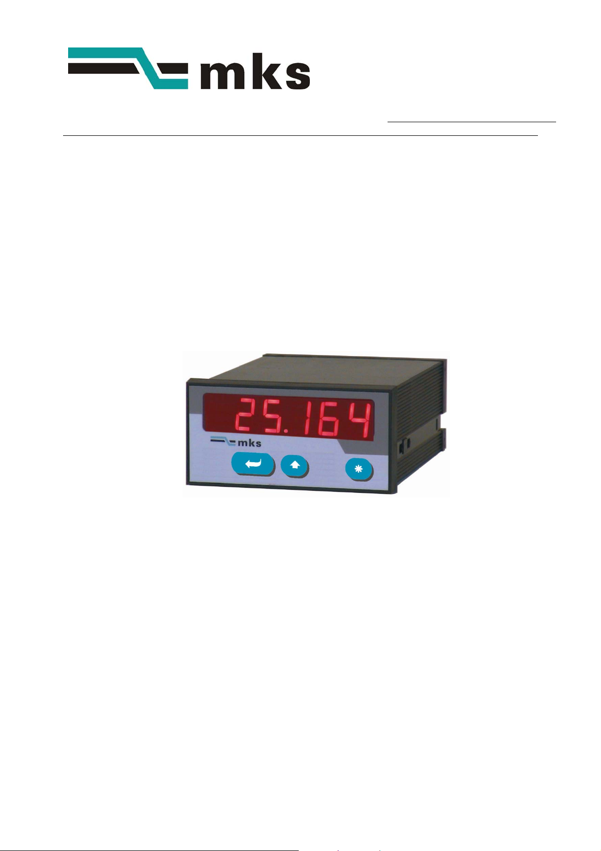
1. Introduction
The AX346 process indicator has been designed for applications requiring superior measuring
technology. The unit provides two separate analogue inputs with individual scaling parameters,
a 6-decade LED display and an adjustable analogue output.
Because of the possibilities to calculate combined values like difference or ratio of the two
inputs, and by the in-built facility of programmable linearisation, this unit is also suitable to
operate as a signal converter (e.g. to convert the ratio of two analogue signals into a
programmable curve and to form a new analogue signal from the result again).
The unit is easy to set-up by means of the front keys and a clear menu structure.
AX346 is built into a standard DIN housing, designed for front panel mounting.
Ax34601a_e_A5.doc / Feb-06 Page 4 / 20
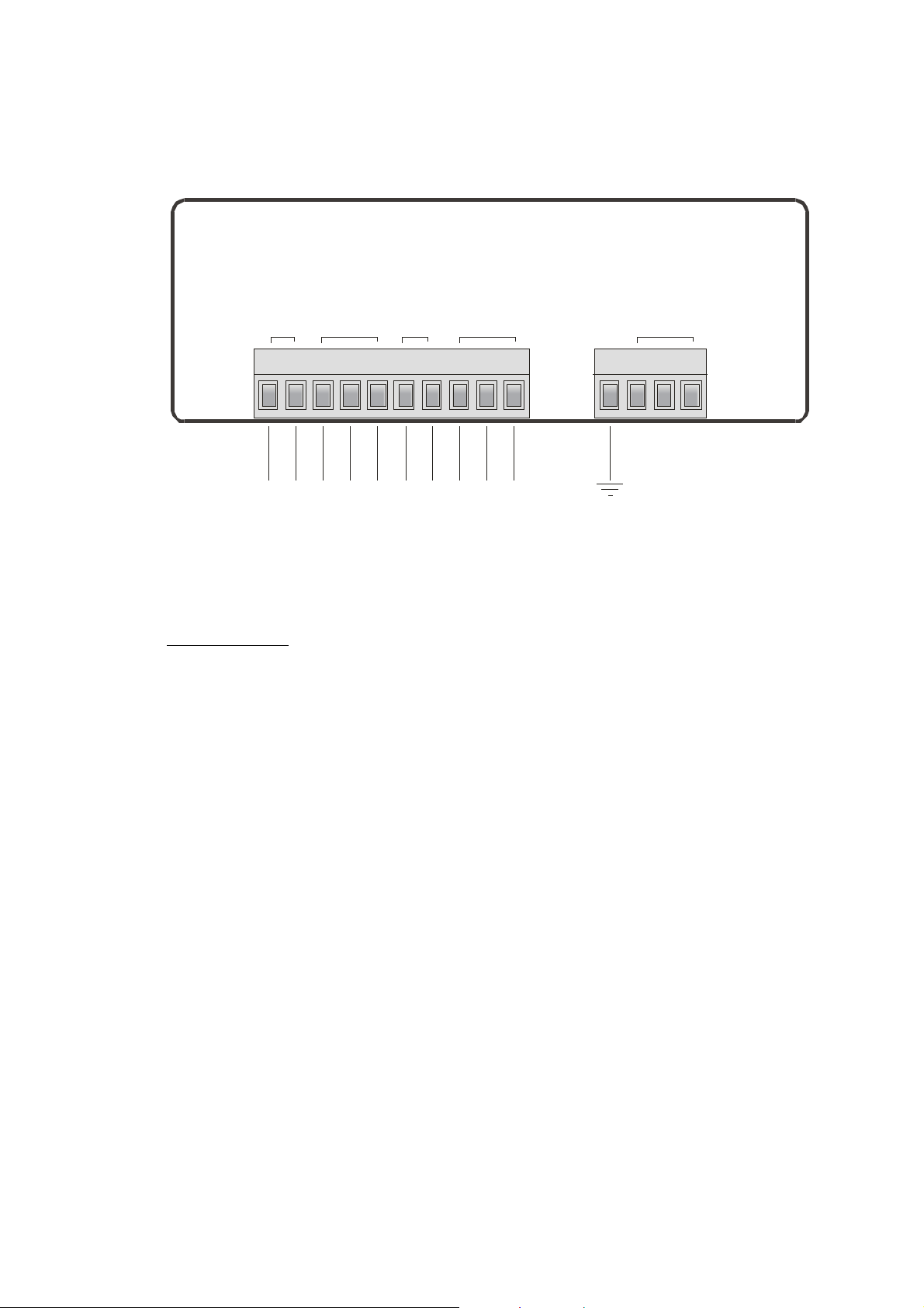
2. Electrical Connections
*) This grounding terminal is internally connected to the GND potential. Grounding of this
terminal is not necessary
however it may be desirable to connect the measuring GND to another ground or earth
potential.
Please note that earthing of this terminal will tie to earth all internal analogue and digital GND
potentials. Multiple earthing should be avoided (e.g. if the minus pole of your DC power supply
should already be earthed externally)
DC po wer supply
Inputs
+/- 10 V or
0 / 4 - 20 mA
aux. power
outpu t
1
2
3 4567 8910
Input B
Input A
GND ( 0V )
+17...30 VCD
GND an al.
+24 V D C
GND ( 0V )
Analog ue output
+/- 10 V
GND anal.
0 / 4 - 20 mA
GND
option al,
AC po wer supply
230 VAC
see*)
0 VAC
115 VAC
, neither for safety nor for EMC reasons. With some applications
2.1. Power Supply
Terminals 1 and 2 provide DC supply from a 17 to 30 volts DC power unit. The current
consumption depends on the level of the input voltage and is typically 130 mA with 17 volts
and 80 mA with 30 volts (sensor current taken from the aux. output not included).
Terminals 0 VAC, 115 VAC and 230 VAC provide supply of the unit directly from the mains. The
total AC power rating is 7.5 VA.
2.2. Auxiliary Power Output
Terminal 7 provides a 24 volts DC output (max. 100 mA) for supply of transducers or sensors.
This output is available with AC power supply and DC power supply as well.
Ax34601a_e_A5.doc / Feb-06 Page 5 / 20

2.3. Analogue Inputs A and B
The unit provides two analogue inputs with a common GND potential (input A and input B)
Both input signals refer to the „Analogue GND“ potential of terminal 5, which internally is
connected to the other GND terminals 1, 6 and GND. Both inputs are individually adjustable as
voltage inputs (+/-10 volts) or current inputs (0/4 – 20 mA), by means of internal jumpers
(see 3.)
Ex factory all jumpers are set to current inputs
2.4. Adjustable Analogue Output
The unit provides a voltage output with ranges 0 – 10 volts or -10 to + 10 volts (output current
max. 2 mA), and a current output 0/4 – 20 mA (external load 0 – 300 Ohms). The resolution of
the output is 14 bits and the update time of the output is approx. 7 milliseconds.
2.5. GND Potential Considerations
Internally, the GND terminals of the analogue inputs and the anlogue outputs are all connected
to the negative terminal of the DC power input. For this reason it is not possible to loop
analogue current signals through several units, except these units are supplied by the AC
terminals, or by means of separate and isolated DC power units.
Ax34601a_e_A5.doc / Feb-06 Page 6 / 20
 Loading...