

MKS 722B User Manual

1034138-001
Revision A, 5/09
MKS Baratron®
Type 722B
Absolute Pressure Transducer

Copyright © 2009 by MKS Instruments, Inc.
All rights reserved. No part of this work may be reproduced or transmitted in any form or by any
means, electronic or mechanical, including photocopying and recording, or by any information
storage or retrieval system, except as may be expressly permitted in writing by MKS Instruments,
Inc.
Baratron® is a registered trademark of MKS Instruments, Inc., Andover, MA
VCR® and VCO® are registered trademarks of Swagelok Company, Solon, OH
Inconel® is a registered trademark of Inco Alloys International, Inc., Huntington, WV

Table of Contents
Table of Contents
Pressure Transducer Safety Information......................................................................................9
Symbols Used in This Instruction Manual......................................................................9
Symbols Found on the Unit............................................................................................10
Safety Procedures and Precautions.................................................................................11
Sicherheitshinweise für den Druckmeßumformer .......................................................................13
In dieser Betriebsanleitung vorkommende Symbole......................................................13
Erklärung der am Gerät angebrachten Symbole.............................................................14
Sicherheitsvorschriften und Vorsichtsmaßnahmen.........................................................15
Informations relatives à la sécurité pour le transducteur de pression ..........................................17
Symboles utilisés dans ce manuel d'utilisation...............................................................17
Symboles apparaissant sur l'unité ...................................................................................18
Mesures de sécurité et précautions .................................................................................19
Medidas de seguridad del transductor de presión........................................................................21
Símbolos usados en este manual de instrucciones..........................................................21
Símbolos hallados en la unidad.......................................................................................22
Procedimientos y precauciones de seguridad..................................................................23
Chapter One: General Information .............................................................................................25
Introduction.....................................................................................................................25
How This Manual is Organized......................................................................................26
Customer Support...........................................................................................................42
Chapter Two: Installation ...........................................................................................................43
How To Unpack the Type 722B Unit.............................................................................43
Unpacking Checklist..........................................................................................43
Product Location and Requirements...............................................................................44
Operating Environmental Requirements............................................................44
Dimensions .....................................................................................................................44
Setup ...............................................................................................................................47
Mounting............................................................................................................47
iii

Table of Contents
Fittings...............................................................................................................48
Making Mechanical Connections ......................................................................48
Connectors.........................................................................................................49
How to Wire a PDR-C and PDR-D Series Readout to a Type 722B
Transducer with a 9-pin Type “D” Connector...................................................51
Electrical Information........................................................................................52
NW-16-KF Fitting Information .........................................................................52
Interface Cables .................................................................................................53
Attaching the Terminal Block Connector Cable................................................55
How To Check the Transducer Zero...............................................................................56
How To Zero the 722B Transducer...................................................................56
Span Adjustment................................................................................................57
Chapter Three: Overview............................................................................................................59
General Information........................................................................................................59
Sensor..............................................................................................................................59
Signal Conditioning Electronics.....................................................................................60
Label ...............................................................................................................................60
Chapter Four: Operation.............................................................................................................61
General............................................................................................................................61
Lowest Suggested Pressure Available for Reading ...........................................61
Lowest Suggested Pressure to Use for Control..................................................61
Chapter Five: Maintenance and Troubleshooting.......................................................................63
General............................................................................................................................63
Zero Adjustment .............................................................................................................63
Troubleshooting..............................................................................................................64
Appendix A: Product Specifications...........................................................................................65
Performance Specifications.............................................................................................65
Physical Specifications ...................................................................................................65
NW-16-KF Fitting Information ......................................................................................65
Electrical Specifications..................................................................................................66
Appendix B: Model Code Explanation.......................................................................................67
Model Code.....................................................................................................................67
iv

Table of Contents
NW-16-KF Fitting Information ......................................................................................69
Index ............................................................................................................................................71
v


List of Figures and Tables
List of Figures and Tables
Figures
Figure 1: Dimensions of the Low Pressure (up to 1000 Torr) Type 722B Transducer..............45
Figure 2: Fitting Dimensions for the Low Pressure Type 722B Transducer..............................45
Figure 3: Dimensions of the High Pressure (>1000 to 25,000 Torr) Type 722B
Transducer ...................................................................................................................................46
Figure 4: Fitting Dimensions of the High Pressure Type 722B Transducer ...............................46
Figure 5: Vertical Mounting Positions........................................................................................47
Figure 6: Acceptable Horizontal Mounting Position..................................................................47
Figure 7: Electrical Scheme for a Voltage Unit..........................................................................52
Figure 8: How To Connect the Cable to a Terminal Block (Example 1)....................................55
Figure 9: How To Connect the Cable to a Terminal Block (Example 2)....................................55
Figure 10: Product Label ............................................................................................................60
Tables
Table 1: Definition of Symbols Found on the Unit ...................................................................... 10
Tabelle 2: Bedeutung der am Gerät angebrachten Symbole.........................................................14
Tableau 3: Définition des symboles apparaissant sur l'unité ........................................................ 18
Tabla 4: Definición de los símbolos hallados en la unidad...........................................................22
Table 5: Pinout of the 9-Pin Type “D” Connector........................................................................ 49
Table 6: Pinout of the 5-Pin Terminal Block Connector..............................................................49
Table 7: Pinout of the 15-Pin Type “D” Connector...................................................................... 50
Table 8: Connections Between a Transducer with a Type “D” Connector and a PDR-C /- D
Readout.......................................................................................................................................... 51
Table 9: Interface Cables ..............................................................................................................53
Table 10: Highest Pressure for Proper Zero Adjustment..............................................................57
Table 11: Suggested Pressures for Reading and Control..............................................................61
Table 12: Troubleshooting Chart..................................................................................................64
vii

List of Figures and Tables
viii
Pressure Transducer Safety Information Symbols Used in This Instruction Manual
Pressure Transducer Safety Information
Symbols Used in This Instruction Manual
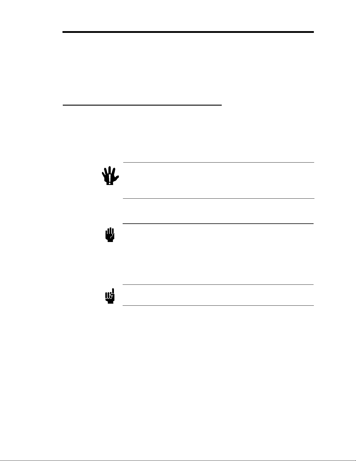
Definitions of WARNING, CAUTION, and NOTE messages used throughout the manual.
Warning
Caution
Note
The WARNING sign denotes a hazard to personnel. It calls
attention to a procedure, practice, condition, or the like, which,
if not correctly performed or adhered to, could result in injury
to personnel.
The CAUTION sign denotes a hazard to equipment. It calls attention
to an operating procedure, practice, or the like, which, if not correctly
performed or adhered to, could result in damage to or destruction of
all or part of the product.
The NOTE sign denotes important information. It calls attention to a
procedure, practice, condition, or the like, which is essential to highlight.
9
Symbols Found on the Unit Pressure Transducer Safety Information
A
Symbols Found on the Unit
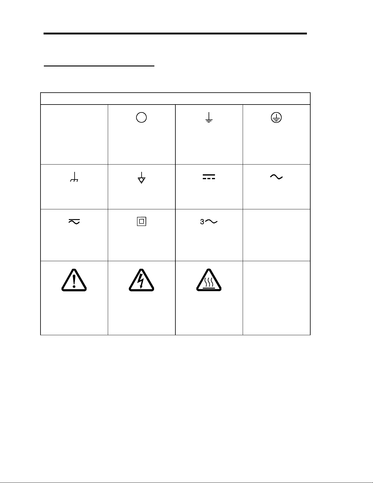
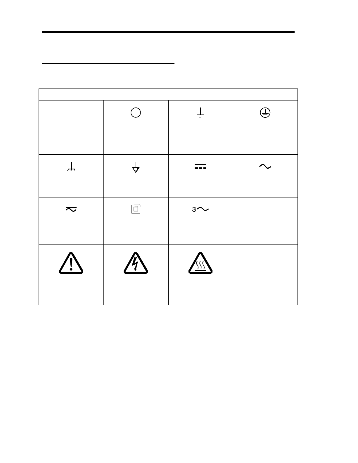
The following table describes symbols that may be found on the unit.
Definition of Symbols Found on the Unit
|
On (Supply)
IEC 417, No.5007
Frame or chassis
IEC 417, No.5020
Both direct and
alternating current
IEC 417, No.5033-a
Off (Supply)
IEC 417, No.5008
Equipotentiality
IEC 417, No.5021
Class ll equipment
IEC 417, No.5172-a
Earth (ground)
IEC 417, No.5017
Direct current
IEC 417, No.5031
alternating current
IEC 617-2 No.020206
Three phase
Protective earth
IEC 417, No.5019
lternating current
IEC 417, No.5032
(ground)
Caution, refer to
accompanying
documents
ISO 3864, No.B.3.1
Caution, risk of
electric shock
ISO 3864, No.B.3.6
Caution, hot surface
IEC 417, No.5041
Table 1: Definition of Symbols Found on the Unit
10

Pressure Transducer Safety Information Safety Procedures and Precautions
Safety Procedures and Precautions
Observe the following general safety precautions during all phases of operation of this
instrument. Failure to comply with these precautions or with specific warnings elsewhere in this
manual violates safety standards of intended use of the instrument and may impair the
protection provided by the equipment. MKS Instruments, Inc. assumes no liability for the
customer’s failure to comply with these requirements.
DO NOT SUBSTITUTE PARTS OR MODIFY INSTRUMENT
Do not install substitute parts or perform any unauthorized modification to the instrument.
Return the instrument to an MKS Calibration and Service Center for service and repair to ensure
that all safety features are maintained.
SERVICE BY QUALIFIED PERSONNEL ONLY
Operating personnel must not attempt component replacement and internal adjustments. Any
service must be made by qualified service personnel only.
USE CAUTION WHEN OPERATING WITH HAZARDOUS MATERIALS
If hazardous materials are used, users must take responsibility to observe the proper safety
precautions, completely purge the instrument when necessary, and ensure that the material used is
compatible with the materials in this product, including any sealing materials.
PURGE THE INSTRUMENT
After installing the unit, or before removing it from a system, purge the unit completely with a
clean, dry gas to eliminate all traces of the previously used flow material.
USE PROPER PROCEDURES WHEN PURGING
This instrument must be purged under a ventilation hood, and gloves must be worn for protection.
DO NOT OPERATE IN AN EXPLOSIVE ENVIRONMENT
To avoid explosion, do not operate this product in an explosive environment unless it has been
specifically certified for such operation.
USE PROPER FITTINGS AND TIGHTENING PROCEDURES
All instrument fittings must be consistent with instrument specifications, and compatible with the
intended use of the instrument. Assemble and tighten fittings according to manufacturer’s
directions.
CHECK FOR LEAK-TIGHT FITTINGS
Carefully check all vacuum component connections to ensure leak-tight installation.
11

Safety Procedures and Precautions Pressure Transducer Safety Information
OPERATE AT SAFE INLET PRESSURES
Never operate at pressures higher than the rated maximum pressure (refer to the product
specifications for the maximum allowable pressure).
INSTALL A SUITABLE BURST DISC
When operating from a pressurized gas source, install a suitable burst disc in the vacuum system
to prevent system explosion should the system pressure rise.
KEEP THE UNIT FREE OF CONTAMINANTS
Do not allow contaminants to enter the unit before or during use. Contamination such as dust,
dirt, lint, glass chips, and metal chips may permanently damage the unit or contaminate the
process.
ALLOW PROPER WARM UP TIME FOR TEMPERATURE-CONTROLLED UNITS
Temperature-controlled units will only meet specifications when sufficient time is allowed for the
unit to meet, and stabilize at, the designed operating temperature. Do not zero or calibrate the
unit until the warm up is complete.
12
Sicherheitshinweise für den Druckmeßumformer In dieser Betriebsanleitung vorkommende Symbole
Sicherheitshinweise für den Druckmeßumformer
In dieser Betriebsanleitung vorkommende Symbole
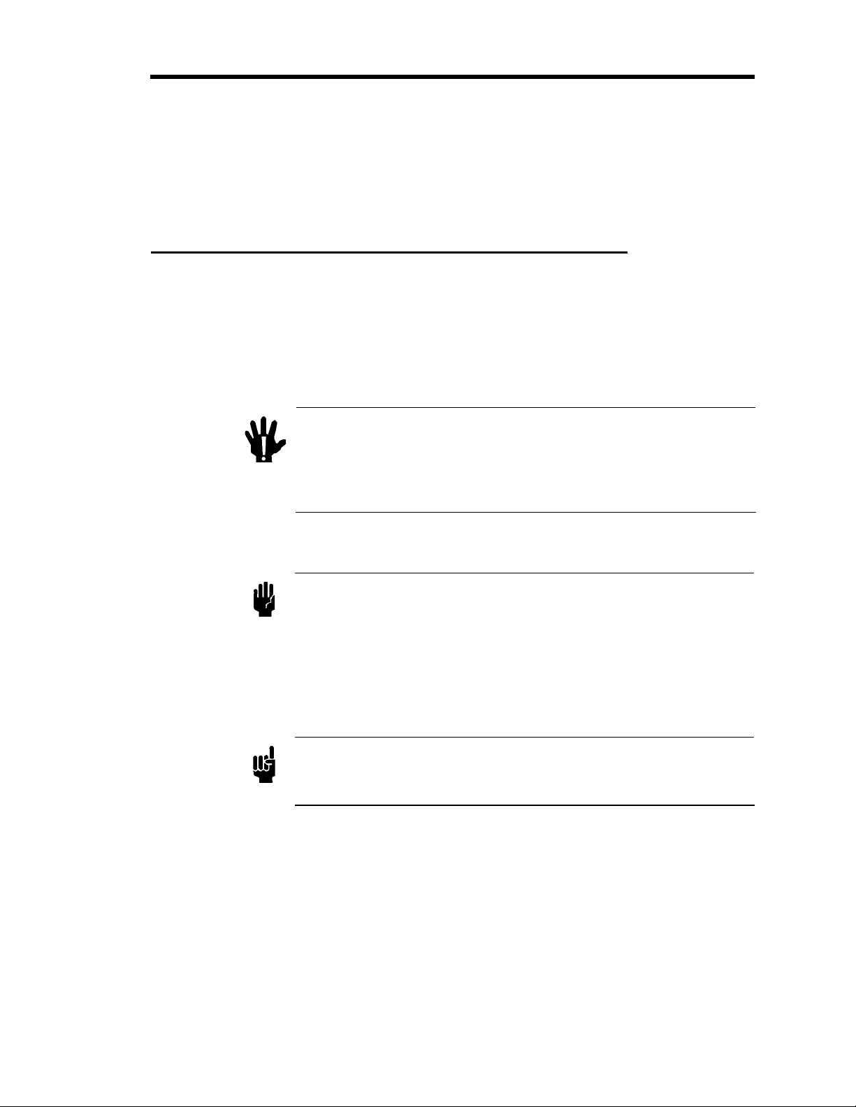
Bedeutung der mit WARNUNG!, VORSICHT! und HINWEIS gekennzeichneten Absätze in
dieser Betriebsanleitung.
Warnung!
Vorsicht!
Hinweis
Das Symbol WARNUNG! weist auf eine Gefahr für das
Bedienpersonal hin. Es macht auf einen Arbeitsablauf, eine
Arbeitsweise, einen Zustand oder eine sonstige Gegebenheit
aufmerksam, deren unsachgemäße Ausführung bzw.
ungenügende Berücksichtigung zu Verletzungen führen kann.
Das Symbol VORSICHT! weist auf eine Gefahr für das Gerät hin. Es
macht auf einen Bedienungsablauf, eine Arbeitsweise oder eine
sonstige Gegebenheit aufmerksam, deren unsachgemäße Ausführung
bzw. ungenügende Berücksichtigung zu einer Beschädigung oder
Zerstörung des Gerätes oder von Teilen des Gerätes führen kann.
Das Symbol HINWEIS macht auf wichtige Informationen bezüglich eines
Arbeitsablaufs, einer Arbeitsweise, eines Zustands oder einer sonstige
Gegebenheit aufmerksam.
13
Erklärung der am Gerät angebrachten Symbole Sicherheitshinweise für den Druckmeßumformer
Erklärung der am Gerät angebrachten Symbole
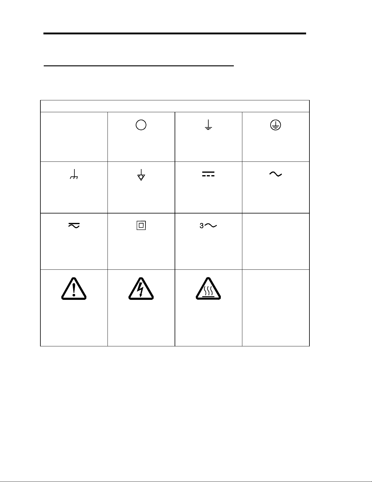
Nachstehender Tabelle sind die Bedeutungen der Symbole zu entnehmen, die am Gerät
angebracht sein können.
Bedeutung der am Gerät angebrachten Symbole
|
Ein (Energie)
IEC 417, No.5007
Masseanschluß
IEC 417, No.5020
Gleich- oder
Wechselstrom
IEC 417, No.5033-a
Aus (Energie)
IEC 417, No.5008
Aquipotential-
anschluß
IEC 417, No.5021
Durchgängige
doppelte oder
verstärkte Isolierung
IEC 417, No.5172-a
Erdanschluß
IEC 417, No.5017
Gleichstrom
IEC 417, No.5031
Wechselstrom
(Drehstrom)
IEC 617-2, No.020206
Dreileiter-
Schutzleiteranschluß
IEC 417, No.5019
Wechselstrom
IEC 417, No.5032
Warnung vor einer
Gefahrenstelle
(Achtung, Dokumen-
tation beachten)
ISO 3864, No.B.3.1
Tabelle 2: Bedeutung der am Gerät angebrachten Symbole
Warnung vor
gefährlicher
elektrischer Spannung
ISO 3864, No.B.3.6
Höhere Temperatur
an leicht
zugänglichen Teilen
IEC 417, No.5041
14

Sicherheitshinweise für den Druckmeßumformer Sicherheitsvorschriften und Vorsichtsmaßnahmen
Sicherheitsvorschriften und Vorsichtsmaßnahmen
Folgende allgemeine Sicherheitsvorschriften sind während allen Betriebsphasen dieses Gerätes
zu befolgen. Eine Mißachtung der Sicherheitsvorschriften und sonstiger Warnhinweise in dieser
Betriebsanleitung verletzt die für dieses Gerät und seine Bedienung geltenden
Sicherheitsstandards, und kann die Schutzvorrichtungen an diesem Gerät wirkungslos machen.
MKS Instruments, Inc. haftet nicht für Mißachtung dieser Sicherheitsvorschriften seitens des
Kunden.
Niemals Teile austauschen oder Änderungen am Gerät vornehmen!
Ersetzen Sie keine Teile mit baugleichen oder ähnlichen Teilen, und nehmen Sie keine
eigenmächtigen Änderungen am Gerät vor. Schicken Sie das Gerät zwecks Wartung und
Reparatur an den MKS-Kalibrierungs- und -Kundendienst ein. Nur so wird sichergestellt, daß alle
Schutzvorrichtungen voll funktionsfähig bleiben.
Wartung nur durch qualifizierte Fachleute!
Das Auswechseln von Komponenten und das Vornehmen von internen Einstellungen darf nur
von qualifizierten Fachleuten durchgeführt werden, niemals vom Bedienpersonal.
Vorsicht beim Arbeiten mit gefährlichen Stoffen!
Wenn gefährliche Stoffe verwendet werden, muß der Bediener die entsprechenden
Sicherheitsvorschriften genauestens einhalten, das Gerät, falls erforderlich, vollständig spülen,
sowie sicherstellen, daß der Gefahrstoff die am Gerät verwendeten Materialien, insbesondere
Dichtungen, nicht angreift.
Spülen des Gerätes mit Gas!
Nach dem Installieren oder vor dem Ausbau aus einem System muß das Gerät unter Einsatz eines
reinen Trockengases vollständig gespült werden, um alle Rückstände des Vorgängermediums zu
entfernen.
Anweisungen zum Spülen des Gerätes
Das Gerät darf nur unter einer Ablufthaube gespült werden. Schutzhandschuhe sind zu tragen.
Gerät nicht zusammen mit explosiven Stoffen, Gasen oder Dämpfen benutzen!
Um der Gefahr einer Explosion vorzubeugen, darf dieses Gerät niemals zusammen mit (oder in
der Nähe von) explosiven Stoffen aller Art eingesetzt werden, sofern es nicht ausdrücklich für
diesen Zweck zugelassen ist.
15

Sicherheitsvorschriften und Vorsichtsmaßnahmen Sicherheitshinweise für den Druckmeßumformer
Anweisungen zum Installieren der Armaturen!
Alle Anschlußstücke und Armaturenteile müssen mit der Gerätespezifikation übereinstimmen,
und mit dem geplanten Einsatz des Gerätes kompatibel sein. Der Einbau, insbesondere das
Anziehen und Abdichten, muß gemäß den Anweisungen des Herstellers vorgenommen werden.
Verbindungen auf Undichtigkeiten prüfen!
Überprüfen Sie sorgfältig alle Verbindungen der Vakuumkomponenten auf undichte Stellen.
Gerät nur unter zulässigen Anschlußdrücken betreiben!
Betreiben Sie das Gerät niemals unter Drücken, die den maximal zulässigen Druck (siehe
Produktspezifikationen) übersteigen.
Geeignete Berstscheibe installieren!
Wenn mit einer unter Druck stehenden Gasquelle gearbeitet wird, sollte eine geeignete
Berstscheibe in das Vakuumsystem installiert werden, um eine Explosionsgefahr aufgrund von
steigendem Systemdruck zu vermeiden.
Verunreinigungen im Gerät vermeiden!
Stellen Sie sicher, daß Verunreinigungen jeglicher Art weder vor dem Einsatz noch während des
Betriebs in das Instrumenteninnere gelangen können. Staub- und Schmutzpartikel, Glassplitter
oder Metallspäne können das Gerät dauerhaft beschädigen oder Prozeß und Meßwerte
verfälschen.
Bei Geräten mit Temperaturkontrolle korrekte Anwärmzeit einhalten!
Temperaturkontrollierte Geräte arbeiten nur dann gemäß ihrer Spezifikation, wenn genügend Zeit
zum Erreichen und Stabilisieren der Betriebstemperatur eingeräumt wird. Kalibrierungen und
Nulleinstellungen sollten daher nur nach Abschluß des Anwärmvorgangs durchgeführt werden.
16
Informations relatives à la sécurité pour le Symboles utilisés dans ce manuel d'utilisation
Informations relatives à la sécurité pour le transducteur
de pression
Symboles utilisés dans ce manuel d'utilisation
Définitions des indications AVERTISSEMENT, ATTENTION, et REMARQUE utilisées dans ce
manuel.
Avertissement
Attention
Remarque
L'indication AVERTISSEMENT signale un danger pour le
personnel. Elle attire l'attention sur une procédure, une
pratique, une condition, ou toute autre situation
présentant un risque d'accident pour le personnel, en
cas d'exécution incorrecte ou de non respect des
consignes.
L'indication ATTENTION signale un danger pour l'appareil.
Elle attire l'attention sur une procédure d'exploitation, une
pratique, ou toute autre situation, présentant un risque
d'endommagement ou de destruction d'une partie ou de la
totalité de l'appareil, en cas d'exécution incorrecte ou de non
respect des consignes.
L'indication REMARQUE signale une information importante. Elle
attire l'attention sur une procédure, une pratique, une condition, ou
toute autre situation, présentant un intérêt particulier.
17
Symboles apparaissant sur l'unité Informations relatives à la sécurité pour le
Symboles apparaissant sur l'unité
Le tableau suivant décrit les symboles pouvant apparaître sur l'unité.
Définition des symboles apparaissant sur l'unité
|
Marche
(sous tension)
IEC 417, No.5007
Masse
IEC 417, No.5020
Courant continu et
alternatif
IEC 417, No.5033-a
Arrêt (hors tension)
IEC 417, No.5008
Equipotentialité
IEC 417, No.5021
Matériel de classe II
IEC 417, No.5172-a
Terre (masse)
IEC 417, No.5017
Courant continu
IEC 417, No.5031
Courant alternatif
IEC 617-2, No.020206
triphasé
Terre de protection
(masse)
IEC 417, No.5019
Courant alternatif
IEC 417, No.5032
Attention : se reporter
à la documentation
ISO 3864, No.B.3.1
Tableau 3: Définition des symboles apparaissant sur l'unité
Attention : risque de
choc électrique
ISO 3864, No.B.3.6
Attention : surface
IEC 417, No.5041
18
brûlante

Informations relatives à la sécurité pour le Mesures de sécurité et précautions
Mesures de sécurité et précautions
Prendre les précautions générales de sécurité suivantes pendant toutes les phases d'exploitation
de cet appareil. Le non respect des ces précautions ou des avertissements contenus dans ce
manuel constitue une violation des normes de sécurité relatives à l'utilisation de l'appareil et
peut diminuer la protection fournie par l'appareil. MKS Instruments, Inc. n'assume aucune
responsabilité concernant le non respect des consignes par les clients.
PAS DE SUBSTITUTION DE PIÈCES OU DE MODIFICATION DE L'APPAREIL
Ne pas installer des pièces de substitution ou effectuer des modifications non autorisées sur
l'appareil. Renvoyer l'appareil à un centre de service et de calibrage MKS pour tout dépannage ou
réparation afin de garantir le l'intégrité des dispositifs de sécurité.
DÉPANNAGE UNIQUEMENT PAR DU PERSONNEL QUALIFIÉ
Le personnel d'exploitation ne doit pas essayer de remplacer des composants ou de faire des
réglages internes. Tout dépannage doit être uniquement effectué par du personnel qualifié.
PRÉCAUTION EN CAS D'UTILISATION AVEC DES PRODUITS DANGEREUX
Si des produits dangereux sont utilisés, l'utilisateur est responsable de la prise des mesures de
précaution appropriées, de la purge complète de l'appareil quand cela est nécessaire, et de la
garantie que les produits utilisés sont compatibles avec les composants de cet appareil, y compris
les matériaux d'étanchéité.
PURGE DE L'APPAREIL
Après l'installation de l'unité, ou avant son enlèvement d'un système, purger l'unité complètement
avec un gaz propre et sec afin d'éliminer toute trace du produit de flux utilisé précédemment.
UTILISATION DES PROCÉDURES APPROPRIÉES POUR LA PURGE
Cet appareil doit être purgé sous une hotte de ventilation, et il faut porter des gants de protection.
PAS D'EXPLOITATION DANS UN ENVIRONNEMENT EXPLOSIF
Pour éviter toute explosion, ne pas utiliser cet appareil dans un environnement explosif, sauf en
cas d'homologation spécifique pour une telle exploitation.
UTILISATION D'ÉQUIPEMENTS APPROPRIÉS ET PROCÉDURES DE SERRAGE
Tous les équipements de l'appareil doivent être cohérents avec ses spécifications, et compatibles
avec l'utilisation prévue de l'appareil. Assembler et serrer les équipements conformément aux
directives du fabricant.
19

Mesures de sécurité et précautions Informations relatives à la sécurité pour le
VÉRIFICATION DE L'ÉTANCHÉITÉ DES CONNEXIONS
Vérifier attentivement toutes les connexions des composants pour le vide afin de garantir
l'étanchéité de l'installation.
EXPLOITATION AVEC DES PRESSIONS D'ENTRÉE NON DANGEREUSES
Ne jamais utiliser des pressions supérieures à la pression nominale maximum (se reporter aux
spécifications de l'unité pour la pression maximum admissible).
INSTALLATION D'UN DISQUE D'ÉCHAPPEMENT ADAPTÉ
En cas d'exploitation avec une source de gaz pressurisé, installer un disque d'échappement adapté
dans le système à vide, afin d'éviter une explosion du système en cas d'augmentation de la
pression.
MAINTIEN DE L'UNITÉ À L'ABRI DES CONTAMINATIONS
Ne pas laisser des produits contaminants pénétrer dans l'unité avant ou pendant l'utilisation. Des
produits contaminants tels que des poussières et des fragments de tissu, de glace et de métal
peuvent endommager l'unité d'une manière permanente ou contaminer le processus.
RESPECT DU TEMPS D'ÉCHAUFFEMENT APPROPRIÉ POUR LES UNITÉS Á
TEMPÉRATURE CONTRÔLÉE
Les unités à température contrôlée atteignent leurs spécifications uniquement quand on leur laisse
un temps suffisant pour atteindre d'une manière stable la température d'exploitation. Ne pas
remettre à zéro ou calibrer l'unité tant que l'échauffement n'est pas terminé.
20
Medidas de seguridad del transductor de presión Símbolos usados en este manual de instrucciones
Medidas de seguridad del transductor de presión
Símbolos usados en este manual de instrucciones
Definiciones de los mensajes de advertencia, precaución y de las notas usados en el manual.
Advertencia
Precaución
Nota
El símbolo de advertencia indica la posibilidad de que se
produzcan daños personales. Pone de relieve un
procedimiento, práctica, estado, etc. que en caso de no
realizarse u observarse correctamente puede causar daños
personales.
El símbolo de precaución indica la posibilidad de producir daños al
equipo. Pone de relieve un procedimiento operativo, práctica,
estado, etc. que en caso de no realizarse u observarse
correctamente puede causar daños o la destrucción total o parcial
del equipo.
El símbolo de notas indica información de importancia. Este símbolo
pone de relieve un procedimiento, práctica o condición cuyo
conocimiento es esencial destacar.
21

Símbolos hallados en la unidad Medidas de seguridad del transductor de presión
Símbolos hallados en la unidad
La tabla siguiente contiene los símbolos que puede hallar en la unidad.
Definición de los símbolos hallados en la unidad
|
Encendido
(alimentación eléctrica)
IEC 417, N° 5007
Caja o chasis
IEC 417, N° 5020
Corriente continua y
alterna
IEC 417, N° 5033-a
Apagado
(alimentación eléctrica)
IEC 417, N° 5008
Equipotencialidad
IEC 417, N° 5021
Equipo de clase II
IEC 417, N° 5172-a
Puesta a tierra
IEC 417, N° 5017
Corriente continua
IEC 417, N° 5031
Corriente alterna
IEC 617-2, N° 020206
trifásica
Protección a tierra
IEC 417, N° 5019
Corriente alterna
IEC 417, N° 5032
Precaución. Consulte
los documentos
adjuntos
ISO 3864, N° B.3.1
Tabla 4: Definición de los símbolos hallados en la unidad
Precaución. Riesgo
de descarga eléctrica
ISO 3864, N° B.3.6
IEC 417, N° 5041
22
Precaución.
Superficie
caliente
 Loading...