

Page 1

Bulletin 50-November-02-05
MVT PLASTIFER®
Perchloric Acid Fume Hood
Exhaust System
INSTALLATION, OPERATION, AND MAINTENANCE MANUAL
This publication contains the installation, operation and maintenance instructions for the MVT Plastifer Perchloric Acid
Exhaust System.
M.K. Plastics catalogs and reference material on the above system, provides additional information describin g the
equipment, performance, available accessories, and specifications.
For additional safety information, refer to AMCA publication 410-96, Safety Practices for Users and Installers of
Industrial and Commercial Fans.
For Information on special application requirements, contact M.K. Plastic’s corporate office at (514) 871-9999.
Fig. 1 – MVT Venturi Layout
1
Page 2
Receiving and Inspection
Carefully inspect the venturi/blower and accessories for any damage and shortage immediately upon receipt of the
fan.
• Turn the blower wheel by hand to ensure it turns freely and does not bind.
• Inspect the PVC manual control damper for free operation of all moving parts.
• Record on the Delivery Receipt any visible sign of damage.
This manual deals primarily with the installation and maintenance of the Venturi system in conjunction with it’s FRP
blower. For further, more complete operational & maintenance details on the FRP blower (fan), please refer to MK
Plastics Bulletin ‘Installation, Operation, and Maintenance Manual’ for FRP centrifugal & Inline fans.
WARNING
The venturi blower has rotating parts. Safety
precautions should be exercised at all times during
installation, operation, and maintenance.
ALWAYS
disconnect power prior to working on fan.
Venturi Installation
1. Set the Venturi carefully on the curb, avoiding damage to the water pipe and the electrical heater strip (if
supplied). Confirm that the Venturi stack is 100% vertical for proper washing operation.
2. The water line for the washing ring, spray nozzle and the 120-volt electrical po wer supply for the heater strip
must be below the roof.
3. Provide piping to the water lines, (washing ring and spray nozzle); install a pressure gauge and a 3-way
solenoid valve per washing line. See page .5 for details on the valves.
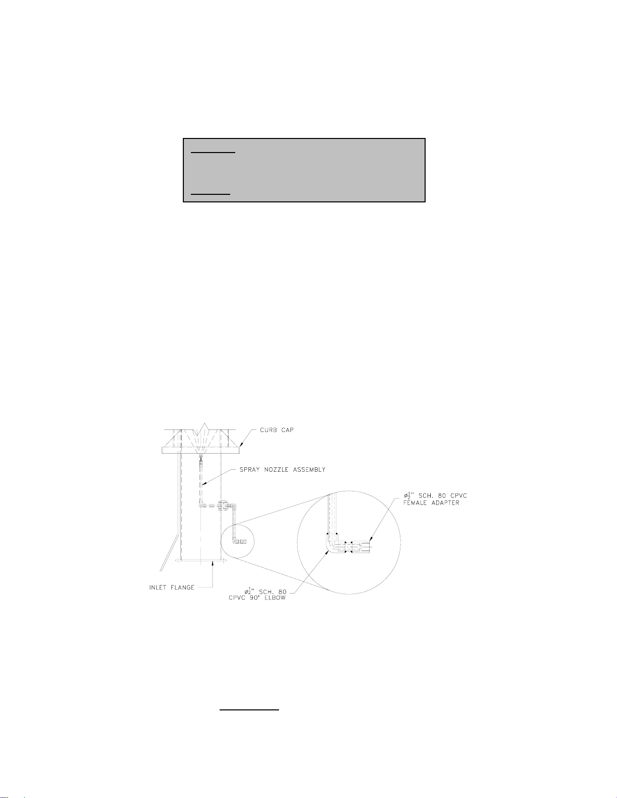
4. The Ø1/2” copper pipe for the Venturi washing ring runs down the length of the stack, protrudes through the
curb cap and stops short of the inlet flange for connection. The end of the pipe will be unthreaded. For the
spray nozzle attachment, there will be a Ø1/2” sch. 80 CPVC female adapter for the incoming water line.
Insure there is no debris in the adapter prior to piping connection. See Fig. 2 for details. The heater cable
will have a standard 120-volt plug for outlet electrical connection.
Fig. 2 – Spray Nozzle Detail
5. The installation of the solenoid valves should be as close as possible to the washing units, (spray
nozzles/washing rings), as detailed in the submittal. The control timer can be located as required. F or further
details regarding the washing sequence, see Fig. 4 & Fig .5.
6. Connect the Venturi stack to the perchloric acid hood by means of ductwork. Use 316 stainless steel,
unplasticized PVC or FRP ducting for corrosion resistance. Avoid any metal contact with the exhausted
fumes, such as fastening bolts or screws. Use only gasketing that is resistant to perchloric acid.
7. The weight of the ductwork should not be
used to support the weight, similar to as shown in Fig. 3.
2
supported by the ventruri stack. Additional supports must be
Page 3

Fig. 3 – Support Details (Typ.)
8. Set the Venturi blower on the roof and connect the blower outlet to stack by means of the PVC flexible
connector, PVC manual control damper and PVC reducer (all provided). Refer to MK Plastics Bulletin
‘Installation, Operation, and Maintenance Manual’ for FRP centrifugal & Inline fans on details on how to
mount the FRP blower (fan). The air pressure from the blower in the Venturi will create a vacuum to induce
air to be exhausted from the hood. Note, if an adjustment is required to the exhausted air volume, this can
be done via. the PVC control damper.
Fig. 4 – Washing Schematic (Typ.)
3
Page 4

Venturi Wash Controller (if supplied)
Perchloric acid is extremely dangerous because it is a very strong oxidizer. Dry perchloric acid crystals ar e unstable,
and when subject to shock or vibration, can explode. For this reason the Venturi stack is supplied with a washing ring
and spray nozzle for periodic washing (flushing) of the duct work to remove accumulated wall deposits, which are
soluble in water. The ‘MVT Plastifer Perchloric Acid Wash Controller’ used in conjunction with the Perchloric Acid
Exhaust Venturi system, safely and automatically washes perchlorates from the system. This control package can be
supplied by MK Plastics. See Fig. 4 to Fig. 5 for details.
Through the use of a field programmable microprocessor, wash water is directed via solenoid valv es to each wash
point in the venturi system. When the researcher shuts off the MVT Venturi exhaust fan, the wash system is
energized, sequencing wash water to be directed to the venturi wash ring first, the inlet venturi wash nozzle, second,
and then the auxiliary duct mounted wash rings. This wash cycle continues in descending order (from the top of the
system to the bottom) toward the perchloric fume hood. Wash duration per wash nozzle is fully programmable.
Wash Controller Specification
1. Control unit shall be enclosed in a NEMA 1 enclosure that shall be remotely mounted and located in the
laboratory. The control panel shall house the microprocessor, electronic switches and wiring terminals. The
panel shall have controls consisting of MVT blower Manual/On-Off switch, indicator lights, and
microprocessor display per fan, all mounted on enclosure door. Power input shall be 120 VAC.
2. Interconnecting wiring between the controller and wash solenoid panel, and the water piping between the
wash solenoid panel and the wash rings shall be the responsibility of the installing contractor.
3. A facility safety engineer shall determine the wash cycle duration and the wash duration of each nozzle.
The safety engineer shall then insure the correct programming of the wash cycle.
4. The wash cycle can be fully programmable, or have manual override by pressing the stop button.
5. Upon blower shut down, the wash system sequence shall be initiated, energizing the respective solenoid
valve, starting the wash cycle at the highest wash nozzle, and continuing down through all the wash nozzles
and rings in the perchloric exhaust system. The user has the option to have the blower operational during
the wash.
6. The total wash cycle duration and the wash duration of each nozzle shall be based upon the correct
programming of the MVT wash cycle timer by the facility safety engineer.
7. Upon completion of the wash cycle, the system shall reset itself to the OFF mode.
8. Refer to MK Plastics programming guide for specific programming information. A detailed ‘T raining Guide’
booklet will be included with each timer; this gives information on wiring, istallation and programing.
Fig. 5 – Control Timer
Wiring (TYP.)
4
Page 5

The 3-Way Solenoid Valves
These valves are 3-way, diaphragm operated, solenoid pilot controlled. T hey are made of brass with only four moving
parts: a core assembly, two diaphragm assemblies, and a disc holder sub-assembly.
Normally Closed – see Fig. 6
Solenoid De-energized: Flow is from cylinder ‘A’ to exhaust ‘E’. Pressure ‘P’ connection is closed.
Solenoid Energized: Flow is from pressure ‘P’ to cylinder ‘A’. Exhaust ‘E’ connection is closed.
The valve is designed to perform properly when mounted in any position. Ho wever, for optimum life and performance,
the solenoid should be mounted vertically and upright to reduce the possibilit y of foreign matter accumulating in the
solenoid base sub-assembly area. The flow direction and pipe con nection of the valves are indicated on the body;
pipe connections have to be in accordance with the size indicated on the nameplate and fitted accordingly. To protect
the solenoid valves, install a strainer or filter at the inlet side as close to the valve as possible.
Clean the valves periodically; in general, if the voltage to the solenoid is correct, sluggish valve operation, excessive
noise, or leakage will indicate that cleaning is required. Clean valve strainer or filter when cleaning the valve. Causes
of improper operation are as follows –
1. Incorrect Pressure: check valve pressure, the pressure to the valve must be within the range specified on
the nameplate. Pressure recommended for the Venturi washing is stated on the submittal, and may vary
depending on a particular job.
2. Excessive Leakage: Disassemble the valve and clean all parts. Replace worn or damaged parts.
Fig. 6 – 3-Way Solenoid Valve Flow Diagram
Operation and Maintenance Instructions
1. The blower must be in operation when perchloric acid exhaust hood is being utilized.
2. Program the timer to open the solenoid valves for the duration as required by the facility safety engineer. Set
washing intervals as often as necessary depending on the frequency of use of the perchloric acid hood by
examining for sediments at the back of the hood.
3. Connect the heater strip at the bottom of the Venturi to the 120-volt – 0.5A electrical supply. It must be on a
different circuit than the disconnect switch. The heater comes with a thermostat, which is built in and
maintenance free. The heater strip, (or cable), remains wrapped around the washing ring water pipe all year
round, but it is recommended disconnecting the power at the end of the season when the temperature
remains above 50ºF. The thermostat turns the cable on when exposed to temperatures below 38ºF. It will
shut off when the pipe has been heated to 45ºF. At the end of the cable, bottom of venturi stack, is a
standard electrical plug for an outlet. We strongly recommend the use of a GFCI protected circuit and not to
overload the outlet. If an extension cord is necessary, use only a properly sized, grounded, CSA/UL C ertified
cord suitable for outdoor service.
4. Water to the washing ring/nozzle must be made available and a pressure gauge installe d to assure sufficient
pressure and flow.
5. At start of system read the pressure gauge on the water pipe to confirm that it agrees with MK Plastics
specifications.
6. Verify at set periods that the wash controller is operational and functioning properly.
7. The disposal of the perchloric acid washing liquid must be done according to municipal codes and
regulations governing polluting containments.
5
3-Way Solenoid Valve
Page 6

Auxiliary Washing Rings
As part of the Perchloric Acid Exhaust System, M.K. Plastics supplies (if required) auxiliary washing rings for both
vertical and horizontal sloping duct runs from the Venturi stack to the fume hood. The auxiliary washing ri ngs should
be located every 10’-12’ on vertical ductwork and every 4’-5’ on the horizontal ductwork. See Fig. 7 for typical detail of
the auxiliary washing rings. Spray nozzles (similar to the spray nozzle on the Venturi stack) shoul d also be installed
up and down stream on each elbow. It is recommended, however, that the Venturi stack should be located as close
as possible to the perchloric fume hood, without elbows and horizontal duct runs.
Fig. 7 – Auxiliary Washing Rings
6
 Loading...