

Page 1
Bulletin 60-March 19
th
2009
FRP Centrifugal Dome
d Blower
INSTALLATION, OPERATION, AND MAINTENANCE MANUAL
RKW FRP FANS
The M.K. Plastics catalog on the above corrosion resistant FRP fan, prov ides additional information describing the equipment,
fan performance, available accessories, and specifications.
For additional safety information, refer to AMCA publication 410-96, Safety Practices for Users an d Installers of Industrial and
Commercial Fans.
For Information on special fan application requirements, contact M.K. Plastic’s corporate office at (514) 871-9999.
Receiving and Inspection
Carefully inspect the fan and accessories for any damage and shortage immediately upon receipt of the fan.
Turn the wheel by hand to ensure it turns freely and does not bind.
Inspect the dampers (if supplied) for free operation of all moving parts.
Record on the Delivery Receipt any visible sign of damage.
WARNING
This unit has rotating parts. Safety precautions
should be exercised at all times during installation,
operation, and maintenance.
ALWAYS
disconnect power prior to working on fan.
Fig. 1 – The RKW Fan
1
Page 2
Storage
If the fan is stored for any length of time prior to installation, completely coat the bearings, (if the fan has pill ow-block bearings),
with grease or moisture inhibiting oil (refer to Lubricants on page 8). Rotate the wheel several revolutions every three to five
days to keep a coating of grease on all internal bearing parts.
Outdoor Storage
To maintain good working condition of the fan when it is stored outdoors, follow the additional instructions belo w.
1. Cover the outlet to prevent the accumulation of dirt and moisture in the housing.
2. Periodically rotate the wheel and operate dampers (if supplied).
3. Periodically inspect the unit to prevent damaging conditions.
Personal Safety
Disconnect switches are recommended. Place the disconnect
switch near the fan in order that the pow er can be swiftly cut
off in case of an emergency, and in order that maintenance
personnel are provided complete control of the power source.
Fan Installation
Roof Mounted Fans
Roof mounted fans should normally be attached to equipment sup port cur bs to keep them above th e roof line b y at least 12”. To
install the roof curb, the fan must be disassembled to be able to attach the fan to the curb. See Fig. 2 for details.
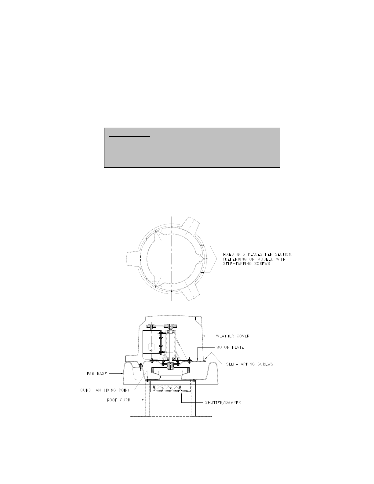
Fig. 2 – Roof Curb Mounted
2
Page 3
Roof Curb Attachment
Please refer to Fig. 2. To attach an assembled fan onto a roof curb, do the following –
1. Remove the weather cover; it is attached to the motor plate with self-tapping screws.
2. Unbolt and remove the motor plate, complete with the motor/flange-bearing and wheel assembly.
3. If a shutter or damper is to be installed, then insert inside the roof curb, or attach to the underside of the fan base,
depending on the type used.
4. Position the fan base section on top of the roof curb. Rotate the base so that the roof drain is on the outside of the curb
for water run-off.
5. Fasten the fan base section to the roof curb with counter sunk, self-tapping screws at center distances as shown on the
submittal ‘Technical Data’ sheets. Lag screws may also be used, as long as the bolt head is flush with the top of the
curb.
6. Reassembly of the fan parts are the reversal of disassembly.
Wall Attachment
The fan is attached in a similar way to roof mounting, except that the curb is replaced by spacer blocks or frame, (not supplied).
See Fig. 3 for details.
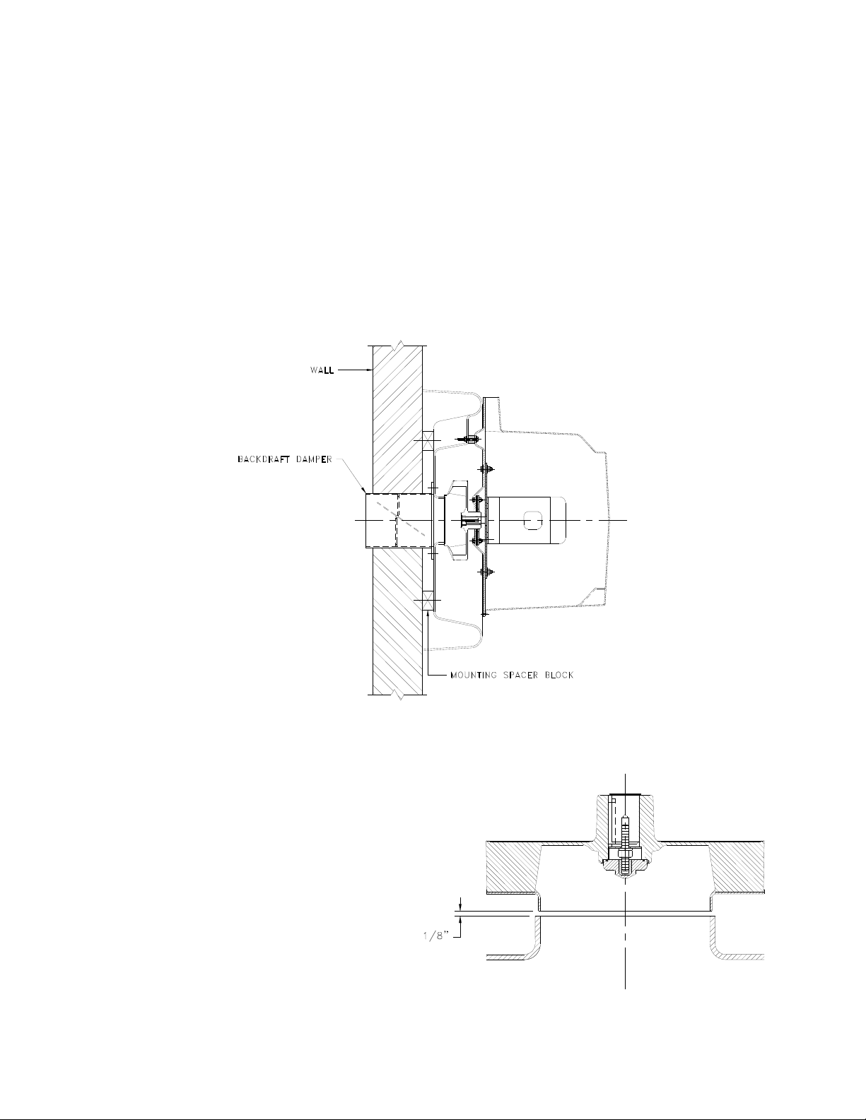
Fig. 3 – Wall Mounted
Wheel-to-Inlet Clearance/Overlap
The correct wheel-to-inlet clearance/overlap is critical to
proper fan performance. This clearance should be verified
before initial start-up since rough handling during shipment
could cause a shift in fan components. Refer to Fig. 4 Wheel/Inlet clearance for details – the gap should be 1/8”
on all sizes of RKW fans.
Fig. 4 – Wheel/Inlet Clearance
3
Page 4

Belt and Pulley Installation
Belt tension is determined by the sound th e belts make when the fan is first started. Belts will produce a loud squeal, which
dissipates after the fan is operating at full capacity. If the belt tension is too tight or too loose, lost efficiency and possible
damage can occur. Do not change the pulley pitch diameter to chan ge tension. This will result in a different fan speed than
desired.
1. Loosen motor plate adjustment nuts and move the motor plate in order that the belts ca n easily s lip into the grooves on
the pulleys. Never pry, roll, or force the belts over the rim of the pulley.
2. Slide the motor plate back until proper tension is reached. F or proper tension a deflection of approximat ely ¼” per foot
of center distance should be obtained by firmly pressing the belt. Refer to Fig. 5.
3. Lock the motor plate adjustment nuts in place.
4. Ensure pulleys are properly aligned. Refer to Fig. 7
Fig. 5 – Belt & Pulley Tension
Pulley Alignment
Pulley alignment is adjusted by loosening the motor pulley setscrew and by moving the motor pulley on the motor shaft, or by
moving the entire motor along the motor mounting bracket. Fig. 6 illustrates correct and incorrect pulley alignment
Fig. 6 – Pulley Alignment
A recommended method of inspecting the pulley alignment is shown in Fig. 7. With the shorter leg of a carpenter’s square or
other straight edge lying along the case of the motor, adjust the position of the motor pul ley (or the motor) until the l onger leg of
the square is parallel to the belt. For more accuracy – use a laser alignment tool, if available. Read the instructions that come
with the kit.
.
Wiring Installation
Fig. 7 – Pulley Alignment Method
4
Page 5

All wiring should be in accordance with local ordinances and the National Electrical Code, NFPA 70. Ensure the power supply
(voltage, frequency, and current carrying capacity of wires) are in accordance with the motor nameplate.
Lock off all power sources before unit is wired to power source.
Leave enough slack in the wiring to allow for motor mov ement when adjusting belt tension. Some fractional mot ors have to be
removed in order to make the connection with the terminal box at th e end of the motor. To remove the motor, remove bolts
securing motor base to power assembly. Do not rem ove motor mou nting bolts. T he fans will have a hol e provided at the base of
the bearing pedestal to accommodate wiring.
Personal Safety
Disconnect switches are recommended. Place the disconnect
switch near the fan in order that the pow er can be swiftly cut
off in case of an emergency, and in order that maintenance
personnel are provided complete control of the power source.
Follow the wiring diagram in the disconnect switch and the wiring diagram provided with the motor. Correctly label the
circuit on the main power box and always identify a closed switch to promote safety (i.e. red tape over a closed switch).
Wiring Diagrams
Single Speed, Single Phase Motor
3 Phase, 9 Lead Motor
When ground is required, attach to ground A or B with No. 6 thread
forming screw. To reverse, interchange T-1 and T-4 leads.
2 Speed, 2 Winding, Single Phase Motor
When ground is required, attach to ground A or B with No. 6 thread
forming screw. To reverse, interchange T-1 and T-4 leads.
Single Speed, Single Phase, Dual Voltage
When ground is required, attach to ground A or B with No. 6 thread
forming screw. To reverse, interchange T-5 and J-10 leads.
To reverse, interchange any 2 line leads.
2 Speed, 1 Winding, 3 Phase Motor
To reverse, interchange any 2 line leads. Motors require magnetic
control.
2 Speed, 2 Winding, 3 Phase
To reverse: High speed-interchange leads T11 & T12.
Low speed-interchange leads T1 & T2. Both speeds-interchange any
2 line leads.
5
Page 6

Final Installation Steps
1. Inspect fasteners and setscrews, particularly fan mounting and bearing fasteners, and tighten according to the
recommended torque shown in the table Recommended Torque for Setscrews/Bolts.
2. Inspect for correct voltage with voltmeter.
3. Ensure all accessories are installed.
Recommended Torque for Setscrews/Bolts (IN/LB)
Operation
Pre-Start Checks
1. Lock out all the primary and secondary power sources.
2. Ensure fasteners and setscrews, particularly those used for mounting the fan, are tightened.
3. Inspect belt tension and pulley alignment.
4. Inspect motor wiring.
5. Ensure belt touches only the pulleys.
6. Ensure fan and any ductwork are clean and free of debris.
7. Inspect wheel-to-inlet clearance. The correct wheel-to-inlet clearance is critical to proper fan performance.
8. Restore power to the fan.
Start Up
Turn the fan on. In variable speed units, set the fan to its lowest speed and inspect for the following:
1. Direction of rotation.
2. Excessive vibration.
3. Unusual noise.
4. Bearing noise.
5. Improper belt alignment or tension (listen for squealing).
6. Improper motor amperage or voltage.
If a problem is discovered, immediately shut the fan off. Lo ck out all electrical power and check for the cause of the
trouble. See Troubleshooting.
Inspection
Inspection of the fan should be conducted in the first 30 minutes, 8 hour and 24 hour intervals of satisfactor y operation. Durin g
the inspections, stop the fan and inspect as per the Conditions Chart.
30 Minute Interval
Inspect bolts, setscrews, and motor mounting bolts. Adjust and tighten as necessary.
8 Hour Interval
Inspect belt alignment and tension. Adjust and tighten as necessary.
24 Hour Interval
Inspect belt tension, bolts, setscrews, and motor mounting bolts. Adjust and tighten as necessary.
Maintenance
6
Page 7

Establish a schedule for inspecting all parts of the fan. The frequency of inspection depends on the operating co nditions and
location of the fan.
Inspect fans exhausting corrosive or contaminated air within the first month of operation. Fans exhausting contaminated air
(airborne particles) should be inspected every three months, or sooner. Regular inspections are recommended for fans
exhausting non-contaminated air.
It is recommended the following inspection be conducted twice per year.
Inspect bolts and setscrews for tightness. Tighten as necessary. Worn setscrews should be replaced immediately.
Inspect belt wear and alignment. Replace worn belts with new belts and adjust alignment as needed. See Belt and
Pulley Installation on page. 4.
Inspect springs and rubber isolators for deterioration and replace as needed.
Inspect for cleanliness. Clean exterior surfaces only. Removing dust and grease on motor housing assures proper
motor cooling. Removing dirt from the wheel and housing prevents imbalance and damage.
Lubricants
M.K. Plastics uses petroleum lubricant in a lithium base. Other types should not be u sed unless the bearings and lines have
been flushed clean. If another type of grease is used, it should be lithium-based grease conforming to NLGI grade 2
consistencies.
A NLGI grade 2 grease is a light viscosity, low-torque, and rust inhibiting l ubricant that is water resistant. Its temperature range
is from –30ºF to +200ºF and capable of intermittent highs of +250ºF.
Motor Bearings
Motor bearings are pre-lubricated and seal ed. Under normal condit ions they will not require further maintenance for a period of
10 years. However, it is advisable to have your maintenance department remove and disassemble the motor, and lubricate the
bearings after 3 years of operation in excessive heat and or in a contaminated air stream cons isting of airborne particles.
Fan Bearings
RKW fans normally have permanently sealed flange-bearings th at do not require greasing. However, some fans could have
greasable pillow-block bearings. These bearings are lubricated through a grease fitting on the bearing and s hould be lubricated
by the schedule, Conditions Chart.
Conditions Chart
RPM Temperature Fan Status Greasing Interval
100 Up to 120ºF Clean 6 to 12 months
500 Up to 150ºF Clean 2 to 6 months
1000 Up to 210ºF Clean 2 weeks to 2 months
1500 Over 210ºF Clean Weekly
Any Speed Up to 150ºF Dirty 1 week to 1 month
Any Speed Over 150ºF Dirty Daily to 2 weeks
Any Speed Any Temperature Very Dirty Daily to 2 weeks
Any Speed Any Temperature Extreme Conditions Daily to 2 weeks
For best results, lubricate the bearings while the fan is in operation. Pump gre ase in slowly until a slight bea d forms around the
bearing seals. Excessive grease can burst seals resulting in high operating temperatures, thus reducing bearing life.
In the event the bearing cannot be seen, use no more than three injections with a hand-operated grease gun.
Motor Service
Should the motor prove defective within one-year period, contact M.K. Plastics directly, or your nearest motor service
representative.
Changing Shaft Speed
All belt driven fans with motors up to and including 3 hp ( 182T max.) are e quipped with variable pitch motor pulleys. To change
the fan speed, perform the following:
1. Loosen setscrews on driver (motor) pulley and remove key, if equipped.
2. Turn the pulley rim to open or close the groove facing. If the pulley has multiple grooves, all must be adjusted to th e
same width.
3. After adjustment, inspect for proper belt tension and alignment.
Speed Reduction
Open the pulley in order that the belt rides deeper in the
groove (smaller pitch diameter).
Speed Increase
Close the pulley in order that the belt rides higher in the
groove (larger pitch diameter). Ensure that the RPM limits
of the fan and the horsepower limits of the motor are
maintained, which can be read on the motor nameplate.
Pulley & Belt Replacement
7
Page 8

1. Remove pulleys from their respective shafts.
2. Clean the motor and fan shafts.
3. Clean bores of pulleys and coat the bores with heavy oil.
4. Remove grease, rust, or burns from the pulleys and shafts.
5. Remove burrs from the shaft by sanding.
6. Place fan pulley on the fan shaft and motor pulley on its shaft. Damage to the pulleys can occur when excessive force
is used in placing the pulleys on their respective shafts.
7. Tighten in place.
8. Install belts on pulleys and align as described in the Belt and Pulley Installation section.
Flange Bearing & Wheel Replacement
Please refer to Fig. 8 for the following procedures. The fan bearings are housed inside the flange bearing assembly, which
includes the shaft. It is easier and quicker to replace the entire assembly, rather than the bearings themselves.
1. V-belt
2. Motor Pulley
3. Flange-bearing assembly
4. Shaft
5. HEX screws, nuts & washers
6. Shaft seal
7. HEX nut & washers
8. Cap
9. Threaded stud
10. Wheel key
11. Neoprene gasket
Fig. 8 – Flange Bearing Assembly
1. Remove the fan motor cover.
2. Remove the fan drive belt and pulley.
3. Unbolt and remove the motor plate, complete with
the motor/flange-bearing and wheel assembly –
see page 3. for further details. This will give you
access to the wheel.
4. Remove by unscrewing the front protective cap,
and then the nut, washers and threaded stud.
5. Remove the wheel from the shaft – a 2-jaw puller
may be needed.
6. Remove the assembly hardware that holds the
entire flange-bearing assembly to the motor
support. The flange bearing assembly can now be
removed, complete with the shaft.
7. Before replacing the assembly, make sure the
shaft and keys are clean and smooth.
8. Re-attach the flange bearing assembly to the
stand plate, but make sure the gaskets and seals
are in good condition. Replace if necessary.
9. Inspect and clean the bore of the wheel. Gently
slide the wheel onto the shaft after inserting the
key, and re-install the threaded stud, nut and
washers to the shaft, and tighten. Make sure the
wheel hub is sitting well against the snap ring on
the shaft. Re-install the cap and tighten well.
10. Re-attach all the pulleys and adjust the belt
tension.
11. Test run and retighten all screws and bolts if
necessary.
8
Page 9

Troubleshooting
Problem and Potential Cause
Low Capacity or Pressure
Incorrect direction of rotation. Make sure the fan rotates in same direction as the arrows on the mot or or drive belt
assembly.
Poor fan inlet conditions. There should be a straight clear duct at the inlet.
Improper wheel alignment.
Excessive Vibration and Noise
Damaged or unbalanced wheel.
Belts too loose; worn or oily belts.
Speed too high.
Incorrect direction of rotation. Make sure the fan rotates in same direction as the arrows on the mot or or drive belt
assembly.
Bearings need lubrication or replacement.
Fan surge or incorrect inlet condition.
Overheated Motor
Motor improperly wired.
Incorrect direction of rotation. Make sure the fan rotates in same direction as the arrows on the mot or or drive belt
assembly.
Cooling air diverted or blocked.
Improper inlet clearance.
Incorrect fan RPM.
Incorrect voltage.
Overheated Bearings
Improper bearing lubrication.
Excessive belt tension.
Parts List
Fig. 9 – RKW Fan (typical)
9
 Loading...