

Page 1
1
Axijet-V
® &
KVC®
High Plume Exhaust
Bulletin 73-03-February 2014
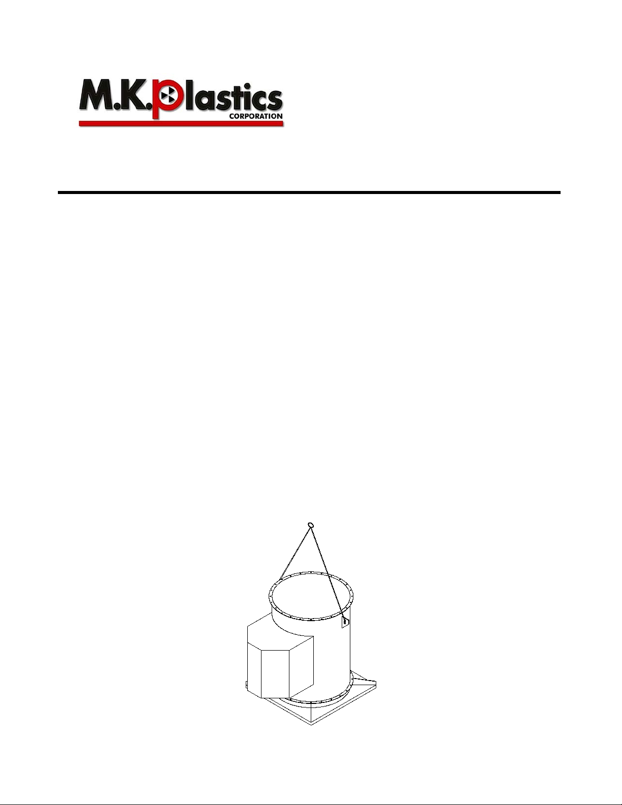
Lifting With Lifting Lugs
Figure-1
INSTALLATION, OPERATION, AND MAINTENANCE MANUAL
Introduction
This bulletin has been prepared to guide the users of Axijet-V In-line Mixed Flow & Centrifugal Fans and
KVC In-line Centrifugal Fans in the proper installation, operation and maintenance procedures to insure
maximum equipment life with trouble-free operation.
Shipping and Receiving
All M.K. Plastics products are carefully constructed and inspected before shipment to insure the highest
standards of quality and performance. Compar e al l components with the bill of lading or packing list to
verify that the proper unit was received. Check each unit for any damage that m ay have occurred in
transit. Any damage should be reported immediately to the carrier and the necessary damage report filed.
Handling
Handling of all air moving equipment should be conducted by trained personnel and be consistent with
safe handling practices. Verify the lif t capacity and operating condition of handling equipment. Maintain
handling equipment to avoid serious personal injury. Units ship ped completely assembled may be lifted
with slings and spreader bars. Use well-padded chain s, cables or nylon straps. On most units, lif ting lugs
are fashioned to protect the fan and fan housi ng from damage (see Figure 1). Never lift a fan by the inlet
or discharge flange, shafting or drives, wheel, motor or motor base, or in any other manner that may bend
or distort parts. If installation is to be delayed, store the unit in a protected area. Prot ect the fan and motor
bearings from moisture and vibration (or shock loading). For extended storage, wrap entire unit in pl ast ic.
Wrap loosely so air may circulate around the fan and m oi st ure does not collect, or use a desiccant.
Extended storage requires monthly inspection s. Check for corrosion or damage to the unit and for debris
within the fan. Rotate the fan wheel a few revolutions. Stop the wheel in a position other than the i nitial
position. Grease the bearings every month wit h a grease compatible with the grease supplied with t he
bearings.
M.K.Plastics Corp. Montréal, Québec www.mkplastics.com
(Standard)
Page 2

2
Fan Installation, Factory Assembled Units
Follow proper handling instructions as given earlier.
1. Move the fan to the final mounting position.
2. Remove skid, crates and packing materials carefully.
3. Attach vibration isolators (if used) to app ropriate mounting clips on fan. Locate fan in position
using lifting instructions above.
4. Carefully level unit using shims (on rigid mounted f ans) at mounting hole locations. Fans mounted
with vibration isolators may be leveled by adjust ing the hardware.
5. Continue with Operations Checklist.
Motor Maintenance
The three basic rules of motor maintenance are:
1. Keep the motor clean.
2. Keep the motor dry.
3. Keep the motor properly lubricated.
Blow dust off periodically (with low pressure air) to prevent motor from overheating. Some smaller m otors
are lubricated for life. Lubrication requirem ents are normally attached to the motor. Use the motor
manufacturer’s recommendations for relubrication. If this information is not available, the following
schedule maybe used. Motors less than 10 HP runni ng about eight hours a day in a clean environment
should be lubricated once every five years; mot ors 15 to 40 HP, every three years. For motors in dusty or
dirty environments or running 24 hours a day: div i de the service interval by 4. Do not over lubricate.
Drive Maintenance and Installation
V-belt drives need periodic inspection, retensioni ng, and occasional belt replacement. When i nspecting
drives, look for dirt buildup, burrs or obstruction s that can cause pr emature belt or drive replacement. If
burrs are found, use fine emery cloth or a stone to remove them. Be careful that dust does not enter t he
bearings.
Check sheaves for wear. Excessive slippage of belts on sheaves can cause wear and vibration. Repl ace
worn sheaves with new ones. Carefully align sheaves to avoid premature sheave failure.
Inspect the belts for wear. If fraying or ot her wear is observed to be mostly on one side of the belts, the
drives may be misaligned. Reinstall the drives ac cording to the following instructions:
1. Slip (do not pound) proper sheave onto corresponding shaft. CAUTION: Placing fan sheave on
motor can over-speed wheel and cause structural failure.
2. Align sheaves with straight edge extended alon g sheaves, just making contact in two places on
outside perimeters of both sheaves.
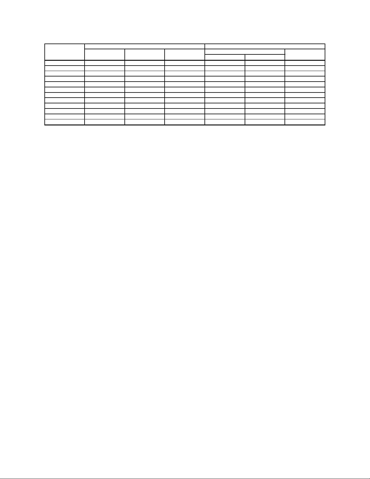
3. Tighten sheave bolts (or setscrews if appropriate). Table1 can be used to determine the amount
of torque required.
4. Install a matched set of belts. Adjust the motor position to obtain slack, install, and tighten belts.
Using a pry bar will damage belts.
5. Tighten belts to proper belt tension. Ideal tension is just enough so that the belts do not slip under
peak load. When using drive tensioning data supplied by V-belt drive manufacturers, new be l ts
can be tensioned to a value 50% greater than for normal operation. This will reduce retensioning
requirements after break-in. Recheck sheave alignment after tensioning.
6. After initial installation of belts, recheck bel t tension again after a few days. (New belts requi re a
break-in period of operation.)
7. When replacing belts, replace the entire set. After initial replacement and tensioning, recheck belt
tension after a few days. (New belts require a break-in period of operation.) Never use belt
dressing on any belts.
8. Fans that have motors and drives mounted at the factory are trim balanced prior to shipment.
This is not possible on units that are shipped without motors and drives. The addition of drive
components in the field can create unbalance forces. MK Plastics recommends final balancing of
the unit after the drive components are installe d. Failure to do so may void the warranty.
M.K.Plastics Corp. Montréal, Québec www.mkplastics.com
Page 3
3
FASTENER
QD
IN IRON IN ALUM. HUB FOR DRIVE
#10 - - - - - 5
0.250-20 5.5 8 12 7.9 7.5 9
0.312-18 11 7 25 16 13 15
0.375-16 22 30 45 29 24 30
0.437-14 30 50 70 - - -
0.500-13 55 75 110 70 - 60
0.562-12 - - - - - 75
0.625-11 100 150 220 - - 135
0.750-10 170 270 380 - - -
0.875-9 165 430 600 - - 1-8 250 645 900 - - -
1.25-7 500 1120 1500 - - -
Tolerance: +5%
For wheel setscrews use Grade 2 values.
The above torque values are for no lubricated fasteners.
BROWNING SPLIT
TAPER BUSHINGS
SIZE
GRADE 2
GRADE 5
GRADE 8
Table-1. Tightening Torque (Ft.-Lbs)
Motor Support Adjustment
Two different types of motor mounts, post and saddle, are used on Axijet-V & KVC fans. Which mount to
use depends on the size of the fan and motor.
On the post type motor mount, the motor plate is supported on four threaded rods. Belt tension is
adjusted by loosening the four nuts on top of the m otor plate and raising the motor plate by adjusting the
four nuts underneath it. The top nuts should then be tightened to hold the motor plate in place.
On the saddle type motor mount, the motor pivots on one side and adjustment of belt tension is achieved
by loosening the nuts on top of the motor plate on the other side, then raising the motor plate by adjusting
the nuts underneath the motor plate. The nuts on top of the motor plate should again be tightened to hold
the motor plate in place. Several holes are provi ded on the pivot side, and the pivot point can be raised
for gross belt adjustment. If this adjustment is made, however, the motor plate should be as parallel as
possible to the fan center plane. Care should be taken to maintain drive alignment and proper bel t
tension.
Bearing Maintenance
Proper lubrication of the fan drive bearings helps assure maximum bearing life. All fans are eq uipped with
decals indicating relubrication intervals f or normal operating conditions. See Table 2A, 2B and 2C for
typical lubrication data. However, every installation is different and the frequency of relubrication sho ul d
be adjusted accordingly.
Observation of the conditions of the grease expelled from the bearings at the time of relubricat i on i s the
best guide as to whether regreasing intervals and amount of grease added should be altered.
Greases are made with different bases. Ther e are synthetic base greases, lithium base, sodium base,
etc. Avoid mixing greases with different bases. They could be i ncompatible and result in rapid
deterioration or breakdown of the grease. The lubrication sticker identifies a list of acceptabl e lubricants.
All bearings are filled with a lithium-based grease before leaving the factory. When the fans are started,
the bearings may discharge excess grease through t he seals for a short period of time. Do not replace
the initial discharge because leakage will cea se when the excess grease has worked out. Sometimes the
bearings have a tendency to run hotter during t hi s period. There is no reason for alarm unless it lasts ov er
48 hours or gets very hot (over 200°F). When relubricating, use a sufficient amount of grease to purge the
seals. Rotate bearings by hand during relubrication.
M.K.Plastics Corp. Montréal, Québec www.mkplastics.com
Page 4
4
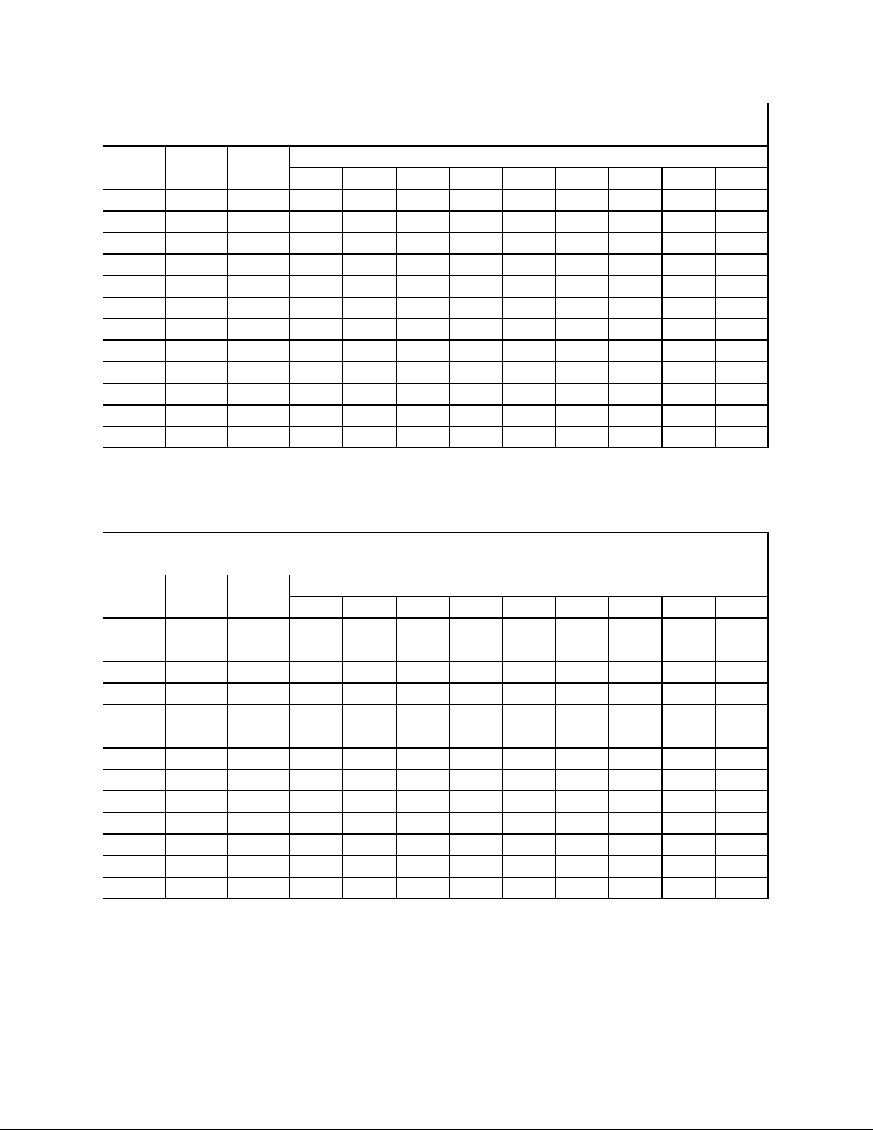
500 1000 1500 2000 2500 3000 3500 4000 4500
1500 1.187 Ball 12 12 10 6 6 4 4 4 2
1825 1.437 Ball 12 12 10 6 6 4 4 4 2
2225 1.437 Ball 12 12 10 6 6 4 4 4 2
2450 1.687 Ball 12 12 10 6 6 4 4 4 2
2700 1.687 Roller 8 4 3 2 1 1 1 1 1
3000 1.937 Roller 8 4 3 2 1 1 1 1 1
3300 2.187 Roller 8 4 3 2 1 1 1 1 1
3650 2.187 Roller 8 4 3 2 1 1 1 1 1
4025 2.187 Roller 8 4 3 2 1 1 1 1 1
4450 2.437 Roller 6 3 2 1 1 0.5 0.5 0 0
4900 2.437 Roller 6 3 2 1 1 0.5 0.5 0 0
5425 2.687 Roller 6 3 2 1 1 0.5 0.5 0 0
Speed [RPM]
Type
Fan Si z e
Shaft Dia .
Relubricat i on Schedule (W eeks) *
Axi j et - VM ( Cl ass 2)
500 1000 1500 2000 2500 3000 3500 4000 4500
1225 1.000 Ball 12 12 10 6 6 4 4 4 2
1500 1.187 Ball 12 12 10 6 6 4 4 4 2
1825 1.437 Ball 12 12 10 6 6 4 4 4 2
2225 1.437 Roller 12 8 8 4 2 2 2 2 1
2450 1.937 Roller 8 4 3 2 1 1 1 1 1
2700 1.937 Roller 8 4 3 2 1 1 1 1 1
3000 2.187 Roller 8 4 3 2 1 1 1 1 1
3300 2.187 Roller 8 4 3 2 1 1 1 1 1
3650 2.187 Roller 8 4 3 2 1 1 1 1 1
4025 2.437 Roller 6 3 2 1 1 0.5 0.5 0 0
4450 2.687 Roller 6 3 2 1 1 0.5 0.5 0 0
4900 2.937 Roller 6 3 2 1 1 0.5 0.5 0 0
5425 3.437 Roller 6 3 2 1 1 0.5 0.5 0 0
Fan Si z e
Shaft Dia .
Type
Speed [RPM]
Relubricat i on Schedule (W eeks) *
Axi j et - VC & KVC (Class 2)
Table-2A. Relubricating Schedule (Weeks) – Axijet-VM (Class 2)
Table-2B. Relubricating Schedule (Weeks) – Axijet-VC & KVC (Class 2)
M.K.Plastics Corp. Montréal, Québec www.mkplastics.com
Page 5

5
500 1000 1500 2000 2500 3000 3500 4000 4500
1825 1.437 Roller 12 8 8 4 2 2 2 2 1
2225 1.437 Roller 12 8 8 4 2 2 2 2 1
2450 1.937 Roller 8 4 3 2 1 1 1 1 1
2700 2.187 Roller 8 4 3 2 1 1 1 1 1
3000 2.437 Roller 6 3 2 1 1 0.5 0.5 0 0
3300 2.437 Roller 6 3 2 1 1 0.5 0.5 0 0
3650 2.937 Roller 6 3 2 1 1 0.5 0.5 0 0
4025 3.437 Roller 6 3 2 1 1 0.5 0.5 0 0
4450 3.437 Roller 6 3 2 1 1 0.5 0.5 0 0
4900 3.437 Roller 6 3 2 1 1 0.5 0.5 0 0
5425 3.937 Roller 5 2 1 0.5 0 0 0 0 0
Fan Si z e
Shaft Dia .
Type
Speed [RPM]
Relubricat i on Schedule (W eeks) *
Axi j et - VC & KVC (Class 3)
*Suggested lubrication interval under ideal continuous operating c onditions. Relubricate while running,
Table-2C. Relubricating Schedule (Weeks) – Axijet-VC & KVC (Class 3)
if safety permits, until some purging occurs at seals. Adjust lubrication frequency depending on
conditions of purged grease. Hours of operation, temperature, and surrounding conditions will affect t he
relubrication frequency required.
1. Lubricate with a high quality NLGI N o. 2 lithium-base grease having rust i nhibitors and
antioxidant additives, and a minimum oil viscosity of 500 SUS at 100°F ( 38°C). Some greases
having these properties are:
a. Shell - Alvania RL
b. Exxon - Ronex MP
c. Mobil - Mobilith SHC100
d. Mobil - Mobilith SHC220
2. Lubricate bearings prior to extended shutdown or storage and rotate s haft monthly to aid
corrosion protection.
Wheel and Shaft Maintenance
Periodically inspect the shaft and wheel f or dirt build up, corrosion, and signs of excess stres s or fatigue.
Clean the components. If the wheel is removed for any reason, make sure that it is securely attached to
the shaft before restarting the fan.
Structural Maintenance
All structural components or devices used to support or attach the fan to a structure should be checked at
regular intervals. Vibration isolators, bolt s, foundations, etc., are all subject to failure from corrosion,
erosion, and other causes. Improper mounting c an l ead to poor operation characteristics or fan fatigue
and failure. Check metallic components for corr osion, cracks, or other signs of stress. Concr ete should be
checked to insure the structural integrity of the foundation.
M.K.Plastics Corp. Montréal, Québec www.mkplastics.com
Page 6

6
MOTOR/DRIVE COVER
JIB CRANE BRACKET
BYPASS DAMPER
& WEATHER COWL
LIFTING LUGS
ROOF CURB
PLENUM
ACCESS DOOR
ISOLATION DAMPER
ENCLOSURE
AXIJET-V
DISCHARGE STACK
WINDBAND
MOTOR/DRIVE COVER
JIB CRANE BRACKET
BYPASS DAMPER
& WEATHER COWL
LIFTING LUGS
ROOF CURB
PLENUM
ACCESS DOOR
ISOLATION DAMPER
ENCLOSURE
AXIJET-V
DISCHARGE STACK
WINDBAND
MOTOR/DRIVE COVER
JIB CRANE BRACKET
BYPASS DAMPER
& WEATHER COWL
LIFTING LUGS
ROOF CURB
PLENUM
ACCESS DOOR
ISOLATION DAMPER
ENCLOSURE
AXIJET-V
DISCHARGE STACK
WINDBAND
MOTOR/DRIVE COVER
JIB CRANE BRACKET
BYPASS DAMPER
& WEATHER COWL
LIFTING LUGS
ROOF CURB
PLENUM
ACCESS DOOR
ISOLATION DAMPER
ENCLOSURE
AXIJET-V
DISCHARGE STACK
WINDBAND
MOTOR/DRIVE COVER
JIB CRANE BRACKET
BYPASS DAMPER
& WEATHER COWL
LIFTING LUGS
ROOF CURB
PLENUM
ACCESS DOOR
ISOLATION DAMPER
ENCLOSURE
AXIJET-V
DISCHARGE STACK
WINDBAND
SIZE 1225
1500
1825
2225 2450 2700 3000 3300 3650
A 12.25
15.00
18.25
22.25
24.50 27.00 30.00 33.00 36.50
B
0.31
0.38
0.56
0.69
0.75
0.88
0.97
1.06
0.94
C (CL 1) 4.69
5.86 7.36
8.89
9.86 10.91
11.89 13.31
14.72
C (CL 2) 4.72
5.86
7.42
8.95
9.86
10.91 11.89 13.31 14.72
C (CL 3)
- - 7.48 9.08 9.92
10.97 12.14
13.38
14.78
SIZE 4025 4450 4900 5425
A
40.25 44.50 49.00 54.25
B
1.03 1.13
1.25 1.38
C (CL 1) 16.23
17.92 19.64 21.70
C (CL 2) 16.23 17.92 19.64 21.70
C (CL 3)
16.30
17.98 19.70 21.83
Note:
Use 'B' dimension for positioning wheel.
Size 1500 1825 2225 2450 2700 3000 3300 3650
A 18.25 22.25 27 30 33 36.5 40.25 44.5
B 0.56 0.69 0.88 0.97 1.06 0.94 1.03 1.13
C 6.19 7.56 9.13 10.19 11.19 12.38 13.63 15.13
Size 4025 4450 4900 5425
A 49 54.25 60 66
B 1.25 1.38 1.56 1.69
C 16.63 18.38 20.25 22.31
Note: Use 'B' dimension for positioning wheel.
NOTE: On KVC fans, the
Table-3. Wheel-Funnel Overlap (Centrifugal Impellers)
discharge stack is replaced
with a velocity cone.
Table-4. Wheel-Funnel Overlap (Mixed-Flow Impellers)
Figure-2. Axijet-V Fan & Plenum Assembly (KVC - Similar)
M.K.Plastics Corp. Montréal, Québec www.mkplastics.com
Page 7

7
Axijet-V or KVC Fan & Plenum Assembly Installation
ANCHOR BOLT
(OR SIMILAR)
ROOF CURB
NEOPRENE VIBRATION PAD
PLENUM CURB CAP
2-
1
2
" x Ø
1
2
" LAG BOLT
PLENUM
ANCHOR BOLT
(OR SIMILAR)
ROOF CURB
NEOPRENE VIBRATION PAD
PLENUM CURB CAP
2-
1
2
" x Ø
1
2
" LAG BOLT
PLENUM
ANCHOR BOLT
(OR SIMILAR)
ROOF CURB
NEOPRENE VIBRATION PAD
PLENUM CURB CAP
2-
1
2
" x Ø
1
2
" LAG BOLT
PLENUM
ANCHOR BOLT
(OR SIMILAR)
ROOF CURB
NEOPRENE VIBRATION PAD
PLENUM CURB CAP
2-
1
2
" x Ø
1
2
" LAG BOLT
PLENUM
ANCHOR BOLT
(OR SIMILAR)
ROOF CURB
NEOPRENE VIBRATION PAD
PLENUM CURB CAP
2-
1
2
" x Ø
1
2
" LAG BOLT
PLENUM
ROOF CURB
ANCHOR BOLT
(OR SIMILAR)
NEOPRENE VIBRATION PAD
2-
1
2
" x Ø
1
2
" LAG BOLT
FAN MOUNTING CAP
AXIJET-V
Depending on the size of equipment, the Axi j et-V/KVC syste m s may arrive in module sections due to
shipping limitations for job site assembly. P l ease contact the factory for further details of specific
components. Generally speaking, the module sections will consist of the following –
1. Roof curb (by M.K. Plastics or by others).
2. Plenum (may or may not have bypass dampers pre-attached, depending on the plenum size).
3. Fan housing.
4. Stack extension or stack sound attenuator (as an accessory).
5. Discharge stack/windband assembly or velocity cone (may include a transition piece depending
on fan size).
Figure-3 & Figure-4 below show a typical method on how to install an Axijet-V/KVC fan or plenum for roof
attachment. Please consult structural engineers or architects for particular attachment requirements or
methods as specific local codes may apply.
Figure-3. Plenum to Curb Attachment Figure-4. Axijet-V Fan to Curb Attachment
(KVC - Similar)
Assuming the roof curb is in place, refer to Figure-3 & Fi gure-4 for the following instructions –
1. Check roof curb for levelness as this could affect drainage from plenum and fan(s). Roof should
be properly and securely fastened to the roof struct ure, as per the project construction documents
and local building codes.
2. Secure the neoprene vibration pads to the t op of the curb wood nailer strip perimeter with either
construction adhesive or counter sunk s elf-tappi ng screws.
3. Lift the plenum onto the curb using a suitable hoist with chains and spreader bar (all plenums will
be supplied with lifting lugs), so that the plenum i s properly centered on the curb. There should be
approximately a 1” gap all around between the insi de plenum curb cap and roof curb.
4. If just the fan is being mounted, the mounting cap comes with pre-drilled holes. Drill 5/16” dia.
pilot holes through the cap holes into the curb wood nailer strip to about 2” depth.
5. If a plenum is being mounted, pre-drill through the steel curb cap 0.56” dia. holes, and then pilot
holes as described above.
6. Secure mounting or curb cap with stainless steel lag bolts. Use anti-seize gel to prevent galling or
welding of the fasteners.
M.K.Plastics Corp. Montréal, Québec www.mkplastics.com
Page 8

8
'H' I.D.
'E' DIST A NCE
'R' SPACES
'C'
Ø0.56 - 'W' HOLES
1
'X'
'C'
'C'
2.75 I.D.
'X'
'T' THICKNESS
'C'
'H' I.D.
'E' DIST A NCE
'R' SPACES
'C'
Ø0.56 - 'W' HOLES
1
'X'
'C'
'C'
2.75 I.D.
'X'
'T' THICKNESS
'C'
'H' I.D.
'E' DIST A NCE
'R' SPACES
'C'
Ø0.56 - 'W' HOLES
1
'X'
'C'
'C'
2.75 I.D.
'X'
'T' THICKNESS
'C'
'H' I.D.
'E' DIST A NCE
'R' SPACES
'C'
Ø0.56 - 'W' HOLES
1
'X'
'C'
'C'
2.75 I.D.
'X'
'T' THICKNESS
'C'
Fan Size C E H R W X T
122 4.75 19.00 23.75 4 5 2.38 0.13
150 5.00 20.00 27.38 4 5 3.69 0.13
182 6.75 27.00 34.88 4 5 3.94 0.13
222 7.75 31.00 40.38 4 5 4.69 0.18
245 8.50 34.00 43.38 4 5 4.69 0.18
270 9.00 36.00 46.75 4 5 5.38 0.18
300 11.00 44.00 51.00 4 5 3.50 0.18
330 12.00 48.00 55.12 4 5 3.56 0.25
365 13.00 52.00 59.88 4 5 3.94 0.25
402 14.00 56.00 64.88 4 5 4.44 0.25
445 15.50 62.00 69.62 4 5 3.81 0.25
490 8.25 66.00 78.00 8 9 6.00 0.25
542 9.50 76.00 88.75 8 9 6.38 0.25
Table-5. Axijet-V/KVC Mounting Cap Dimensions
M.K.Plastics Corp. Montréal, Québec www.mkplastics.com
Page 9

9
NEOPRENE GASKET
(BY M.K. PLASTICS)
AXIJET-V MOUNTING CAP
PLENUM MOUNTING CAP
MOUNTING HA R DW ARE
(BY M.K. PLASTICS)
NEOPRENE GASKET
(BY M.K. PLASTICS)
PLENUM
STACK/WINDBAND
ASSEMBLY
TRANSITION
(DEPENDING ON FAN SIZE)
AXIJET-V
NEOPRENE GASKET
(BY M.K. PLASTICS)
AXIJET-V MOUNTING CAP
PLENUM MOUNTING CAP
MOUNTING HA R DW ARE
(BY M.K. PLASTICS)
NEOPRENE GASKET
(BY M.K. PLASTICS)
PLENUM
STACK/WINDBAND
ASSEMBLY
TRANSITION
(DEPENDING ON FAN SIZE)
AXIJET-V
NEOPRENE GASKET
(BY M.K. PLASTICS)
AXIJET-V MOUNTING CAP
PLENUM MOUNTING CAP
MOUNTING HA R DW ARE
(BY M.K. PLASTICS)
NEOPRENE GASKET
(BY M.K. PLASTICS)
PLENUM
STACK/WINDBAND
ASSEMBLY
TRANSITION
(DEPENDING ON FAN SIZE)
AXIJET-V
NEOPRENE GASKET
(BY M.K. PLASTICS)
AXIJET-V MOUNTING CAP
PLENUM MOUNTING CAP
MOUNTING HA R DW ARE
(BY M.K. PLASTICS)
NEOPRENE GASKET
(BY M.K. PLASTICS)
PLENUM
STACK/WINDBAND
ASSEMBLY
TRANSITION
(DEPENDING ON FAN SIZE)
AXIJET-V
NEOPRENE GASKET
(BY M.K. PLASTICS)
AXIJET-V MOUNTING CAP
PLENUM MOUNTING CAP
MOUNTING HA R DW ARE
(BY M.K. PLASTICS)
NEOPRENE GASKET
(BY M.K. PLASTICS)
PLENUM
STACK/WINDBAND
ASSEMBLY
TRANSITION
(DEPENDING ON FAN SIZE)
AXIJET-V
NOTE: On KVC fans, the
discharge stack is replaced
with a velocity cone.
Axijet-V/KVC to Plenum Installation
Discharge Stack/Windband or Velocity Cone Assembly
Figure-5. Axijet-V Fan Installation (KVC – Similar)
1. Place the 1” wide x 1/8” thick neoprene gasket alo ng the top of the plenum mounting cap
(isolation damper housing).
2. Lower the Axijet-V into place using a suitable hoist and chains. All Axijet-V fans come with lifting
lugs.
3. Align the pre-drilled holes in the fan mounting ca p and the top plenum mounting cap. Make sure
the gasketing is compressed.
4. Secure with stainless steel hardware, provided by M.K. Plastics.
1. Place the 1” wide x 1/8” thick neoprene gasket alo ng the flanges for the fan outlet, transition (if
supplied) and stack/cone. The transition may already be attached t o the stack, depending on fan
size.
2. NOTE: On Axijet-V fans, the discharge stack flan ge hole pattern is not symmetrical, please align
the bolt holes to match those on the fan discharge flange. This allows the bifurcated opening of
the stack to line up a certain way.
3. Using a suitable hoist and straps around the outside of the stack bifurcated section, lift the
assembly onto the fan outlet flange.
4. Secure with stainless steel hardware, provided by M.K. Plastics.
M.K.Plastics Corp. Montréal, Québec www.mkplastics.com
Page 10

10
Drainage Detail
A
B
C
DRAIN COUPLING
PLENUM OR FAN HOUS I N G
A
B
C
DRAIN COUPLING
PLENUM OR FAN HOUS I N G
A
B
C
DRAIN COUPLING
PLENUM OR FAN HOUS I N G
A
B
C
DRAIN COUPLING
PLENUM OR FAN HOUS I N G
A
B
C
DRAIN COUPLING
PLENUM OR FAN HOUS I N G
DISCONNECT SWITCH
STEP-DOWN TRANSFORMER
(208/230/460/575V - 1 PHASE)
FAN MOTOR
(208/230/460/575V - 3 PHASE)
(208/230/460/575V - 3-PHASE)
LINE IN
HIGH VOLTAGE
LOW VOLTAGE
(24V OR 120V - 1 PHASE)
ISOLATION DAMPER ACTUATOR
DISCONNECT SWITCH
STEP-DOWN TRANSFORMER
(208/230/460/575V - 1 PHASE)
FAN MOTOR
(208/230/460/575V - 3 PHASE)
(208/230/460/575V - 3-PHASE)
LINE IN
HIGH VOLTAGE
LOW VOLTAGE
(24V OR 120V - 1 PHASE)
ISOLATION DAMPER ACTUATOR
DISCONNECT SWITCH
STEP-DOWN TRANSFORMER
(208/230/460/575V - 1 PHASE)
FAN MOTOR
(208/230/460/575V - 3 PHASE)
(208/230/460/575V - 3-PHASE)
LINE IN
HIGH VOLTAGE
LOW VOLTAGE
(24V OR 120V - 1 PHASE)
ISOLATION DAMPER ACTUATOR
DISCONNECT SWITCH
STEP-DOWN TRANSFORMER
(208/230/460/575V - 1 PHASE)
FAN MOTOR
(208/230/460/575V - 3 PHASE)
(208/230/460/575V - 3-PHASE)
LINE IN
HIGH VOLTAGE
LOW VOLTAGE
(24V OR 120V - 1 PHASE)
ISOLATION DAMPER ACTUATOR
DISCONNECT SWITCH
STEP-DOWN TRANSFORMER
(208/230/460/575V - 1 PHASE)
FAN MOTOR
(208/230/460/575V - 3 PHASE)
(208/230/460/575V - 3-PHASE)
LINE IN
HIGH VOLTAGE
LOW VOLTAGE
(24V OR 120V - 1 PHASE)
ISOLATION DAMPER ACTUATOR
A. Must be greater than system static
Personal Safety
All Axijet-V/KVC fans and inlet plenums come as standard with outlet drains due to the possibility of water
or condensation that may occur. Proper disposal of water must occur by connection of drain o utlet to a
drainage system (by others). Piping must have adequate pitch for proper runoff and be support ed (if
needed) to prevent the possibility of sagging and overflow. T he trap should be filled before start-up.
pressure, in inches.
B. Must be greater than1/2 of the system
static pressure, in inches.
C. 1” water seal.
Wiring Installation
All wiring should be in accordance with local ordinances and the National Electrical Code, NFPA 70.
Ensure the power supply (voltage, frequency, and current carrying capacity of wires) are in accordance
with the motor nameplate.
Lock off all power sources before unit is wired to power source.
Disconnect switches are recommended. Place the disconnect
switch near the fan in order that the power can be swiftly cut
off in case of an emergency, and in order that maintenance
personnel are provided complete control of the power source.
Figure-6. Isolation Damper Wiring Schematic
M.K.Plastics Corp. Montréal, Québec www.mkplastics.com
Page 11

11
STEP-DOWN TRANSFORMER
(208/230/460/575V - 1 PHASE)
(24V OR 120V - 1 PHASE)
BYPASS DAMPER ACTUATOR
(BY OTHERS)
HIGH VOLTAGE
LOW VOLTAGE
STEP-DOWN TRANSFORMER
(208/230/460/575V - 1 PHASE)
(24V OR 120V - 1 PHASE)
BYPASS DAMPER ACTUATOR
(BY OTHERS)
HIGH VOLTAGE
LOW VOLTAGE
STEP-DOWN TRANSFORMER
(208/230/460/575V - 1 PHASE)
(24V OR 120V - 1 PHASE)
BYPASS DAMPER ACTUATOR
(BY OTHERS)
HIGH VOLTAGE
LOW VOLTAGE
STEP-DOWN TRANSFORMER
(208/230/460/575V - 1 PHASE)
(24V OR 120V - 1 PHASE)
BYPASS DAMPER ACTUATOR
(BY OTHERS)
HIGH VOLTAGE
LOW VOLTAGE
Figure-7. Bypass Damper Wiring Schematic
Operation Checklist
• Verify that proper safety precautions hav e been followed.
• Electrical power must be locked off.
Check fan mechanism components:
• Nuts, bolts, set screws are tight.
• Mounting connections are properly made and tight ened.
• Bearings are properly lubricated.
• Wheel, drives and fan surfaces are clean and t i ghtened.
• Rotating assembly turns freely and does not rub.
• Drives on correct shafts, properly aligned, and pro perly tensioned.
Check fan electrical components:
• Motor is wired for proper supply voltage.
• Motor was properly sized for power of rotating assembly.
• Motor is properly grounded.
• All leads are properly insulated.
Trial “bump”:
• Turn on power just long enough to start assembly rotating.
• Check rotation for agreement with rotation arrow.
• Listen for any unusual noise.
Run unit up to speed:
• Bearing temperatures are acceptable (<200°F) after one to two hours of operation.
• Check for excess levels of vibration. Filter in re adi ngs should be 0.15 inches per second or less.
After one week of operation:
• Check all nuts, bolts and setscrews and tighten if necessary.
• Readjust drive tension if necessary.
M.K.Plastics Corp. Montréal, Québec www.mkplastics.com
Page 12

12
Troubleshooting
Low Capacity or Pressure
Incorrect direction of rotation. Make sure the fan rotates in same direction as the arrows on the motor
• Improper wheel alignment.
Excessive Vibration and Noise
Incorrect direction of rotation. Make sure the fan rotates in same direction as the arrows on the motor
• Fan surge or incorrect inlet condition.
Overheated Motor
Incorrect direction of rotation. Make sure the fan rotates in same direction as the arrows on the motor
• Incorrect voltage.
Overheated Bearings
• Excessive belt tension.
Problem and Potential Cause
•
or drive belt assembly.
• Poor fan inlet conditions. There should be a straight clear duct at the inlet.
• Damaged or unbalanced wheel.
• Belts too loose; worn or oily belts.
• Speed too high.
•
or drive belt assembly.
• Bearings need lubrication or replacement.
• Motor improperly wired.
•
or drive belt assembly.
• Cooling air diverted or blocked.
• Improper inlet clearance.
• Incorrect fan RPM.
• Improper bearing lubrication.
M.K.Plastics Corp. Montréal, Québec www.mkplastics.com
 Loading...