

Page 1
Bulletin 90- 01- NOV2002
FRP Centrifugal & Inline Fans
This publication contains the installation, operation and maintenance instructions for the following corrosion resistant
FRP fans:
INSTALLATION, OPERATION, AND MAINTENANCE MANUAL
• CNW
• PRVS
• DHK
• AXCL
• PVK
M.K. Plastics catalogs on the above corrosion resistant FRP fans, provides additional information describing the equipment, fan
performance, available accessories, and specifications.
For additional safety information, refer to AMCA publication 410-96, Safety Practices for Users and Installers of Industrial and
Commercial Fans.
For Information on special fan application requirements, contact M.K. Plastic’s Corporate office at (514) 871-9999.
Receiving and Inspection
Carefully inspect the fan and accessories for any damage and shortage immediately upon receipt of the fan.
• Turn the wheel by hand to ensure it turns freely and does not bind.
• Inspect the dampers (if supplied) for free operation of all moving parts.
• Record on the Delivery Receipt any visible sign of damage.
Handling
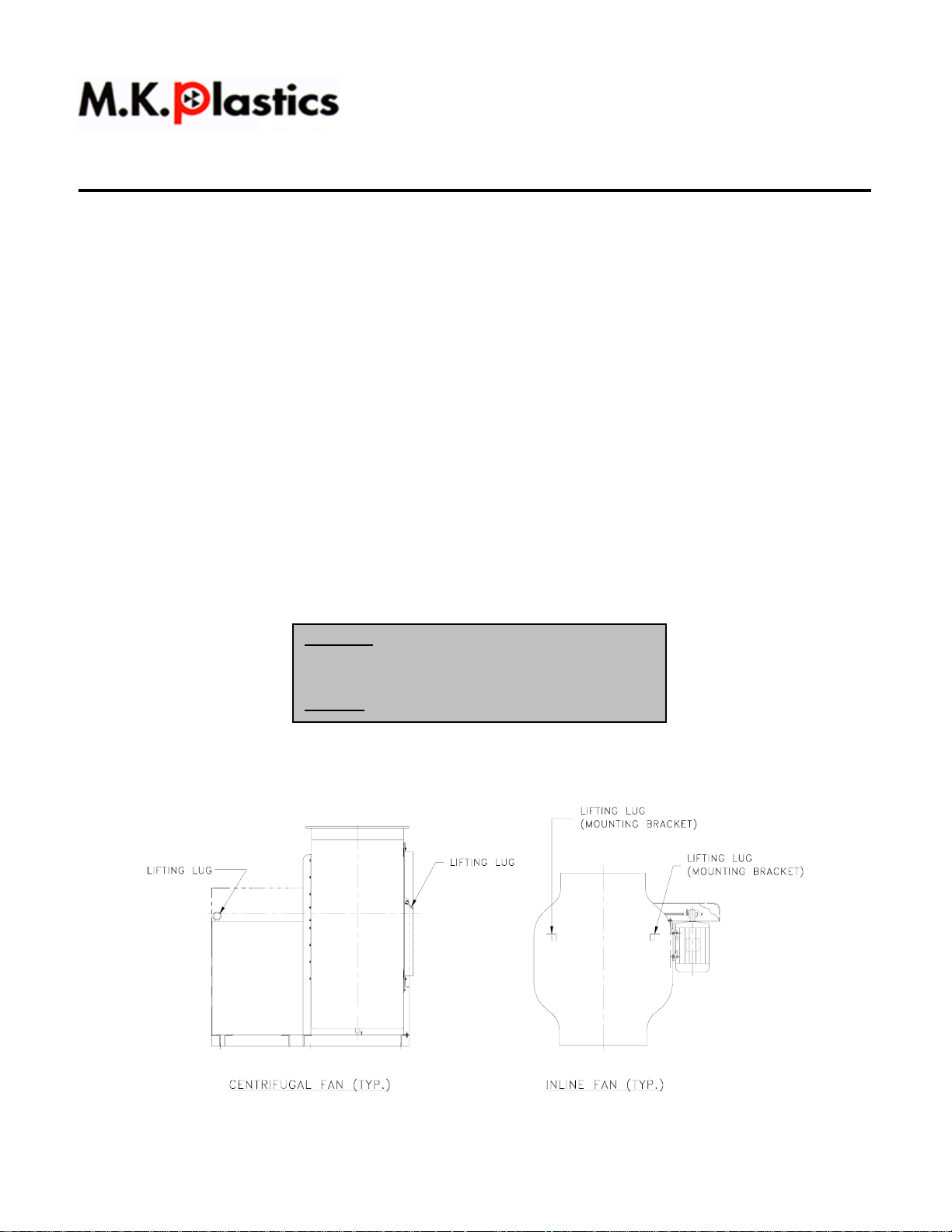
Lift the fan by the base or lifting lugs. Never lift by the shaft, motor or housing. See Fig. 1 – Fan Lifting Lug Details.
WARNING
This unit has rotating parts. Safety precautions
should be exercised at all times during installation,
operation, and maintenance.
ALWAYS
disconnect power prior to working on fan.
Fig. 1 – Fan Lifting Lug Details
1
Page 2
Storage
If the fan is stored for any length of time prior to installation, completely coat the bearings with grease or moisture inhibiting oil
(refer to Lubricants on page 8). Rotate the wheel several revolutions every three to five days to keep a coating of grease on all
internal bearing parts.
Outdoor Storage
To maintain good working condition of the fan when it is stored outdoors, follow the additional instructions below.
1. Cover the inlet and outlet to prevent the accumulation of dirt and moisture in the housing.
2. Periodically rotate the wheel and operate dampers (if supplied).
3. Periodically inspect the unit to prevent damaging conditions.
Personal Safety
Disconnect switches are recommended. Place the disconnect
switch near the fan in order that the power can be swiftly cut
off in case of an emergency, and in order that maintenance
personnel are provided complete control of the power source.
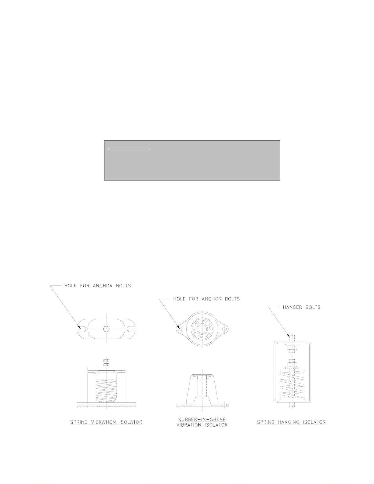
Vibration Isolators
To prevent vibration and noise from being transferred to the building, vibration isolators are recommended. Isolators should be
located between the fan system and the support structure. M.K. Plastics supplies three main types of isolators for FRP fans:
• Floor Mounted Spring Isolators
• Floor Mounted Rubber-In-Shear Isolators
• Hanging Spring Isolators (in-line fans)
In applications where seismic isolators are required, contact M.K. Plastics directly for further details.
Fig. 2 – Floor Mounted Vibration Isolators – (Typical)
2
Page 3

Floor Mounted Rubber-In-Shear Isolators
1. Mount fan on rail supports (if supplied).
2. Elevate fan to provide room to insert isolators between the fan base and supports and block in position.
3. Position isolators under fan and secure bolts.
4. Remove blocks and allow fan to rest on the isolators. Isolators must be installed on a level surface (leveling should not
be required).
5. Secure isolators to mounting surface.
Floor Mounted Spring Vibration Isolators (Refer to Fig. 3)
Fig. 3 – Spring Vibration Isolators (Assembly Detail - Typical)
1. Locate the isolators in their proper position under the fan. The equipment support should be flat and level. Shims, if
required, should be full size.
2. Before the isolators are adjusted, the weight of the fan will cause the top plate to come to rest on the housing. The
isolators should be adjusted to provide a minimum clearance of ¼” between the top plate and the housing.
3. Install the adjusting and leveling bolts through the equipment mounting holes until the bolt comes into contact with the
spring cup. Back off the lock nut and compress the springs by turning the adjusting bolt clockwise. Start at one isolator
and make four turns on the adjusting bolt, move to the next isolator and make four turns, etc., until all isolators have
been adjusted four turns. Repeat this procedure until a ¼” clearance is obtained between top plate and housing.
4. Check the level of the fan. The fan may now be leveled by making small adjustments of individual isolators at the high
and low points. The sleeves of the fan and isolation damper should be in line.
5. After the fan is level, visually check each isolator to make sure spring coils are not closed solid and there is sufficient
clearance between the top plate and housing.
Spring Hanging Vibration Isolators (Refer to Fig. 4)
Fig. 4 – Spring Hanging Vibration Isolators (In-line fans - Typical)
3
Page 4
1. Install the spring hanger as shown in Fig. 4.
2. Only after the fan is in it’s final operating weight should the spring be adjusted. To adjust the spring, turn the nut directly
above the spring cup clockwise. This will compress the spring.
3. When supporting the fan, not more than (3) complete turns should be made on the adjusting nut for each hanger at one
time. Begin at one support point and progress around the fan compressing each spring in turn. This will tend to
compress all springs uniformly and eliminate overloading of individual hangers.
4. Should any point be overloaded, turn the nut counterclockwise. This will unload the spring.
5. Check the level of the fan. The fan may now be leveled by making small adjustments of the individual isolators.
6. After the fan is level, visually check each isolator to make sure the spring coils are not closed solid.
Duct Installation
Efficient fan performance relies on the proper installation of inlet ducts (where factory inlet plenums are not provided). For duct
inlets, allow at least 3 fan wheel diameters between duct turns or elbows and the fan inlet. See Fig. 5 below.
Fig. 5 – Inlet Duct Turns
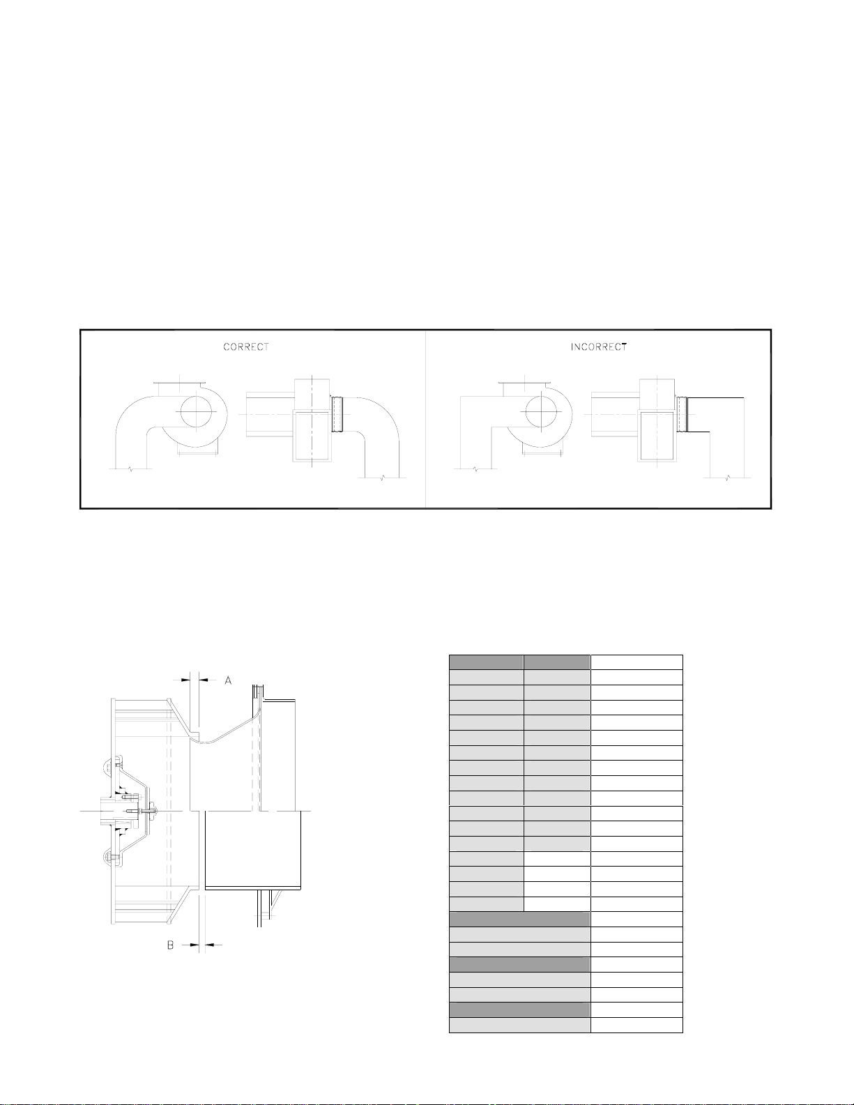
Wheel-to-Inlet Clearance/Overlap
The correct wheel-to-inlet clearance/overlap is critical to proper fan performance. This clearance should be verified before initial
start-up since rough handling during shipment could cause a shift in fan components. Refer to Fig. 6 - Wheel/Inlet Overlap for
details.
Fig. 6 – Wheel/Inlet Clearance/Overlap
DHK AXCL DIM A (in)
1225 1225 9/16”
1500 1500 5/8”
1825 1825 3/4"
2225 2225 15/16”
2450 2450 1-1/32”
2700 2700 1-1/16”
3000 3000 1-5/16”
3300 3300 1-11/32”
3650 3650 1-1/2”
4025 4025 1-5/8”
4450 4450 1-13/16”
4900 4900 2”
5425 2-1/8”
600 2-3/8”
6600 2-1/2”
7300 2-3/4”
PVK DIM A (in)
500 1”
670 1-1/4”
CNW DIM B(in)
160-200 1/8”
250-400 3/16”
PRVS DIM B (in)
63-250 1/8”
4
Page 5

Belt and Pulley Installation
Belt tension is determined by the sound the belts make when the fan is first started. Belts will produce a loud squeal, which
dissipates after the fan is operating at full capacity. If the belt tension is too tight or too loose, lost efficiency and possible
damage can occur. Do not change the pulley pitch diameter to change tension. This will result in a different fan speed than
desired.
1. Loosen motor plate adjustment nuts on L-bolts and move motor plate in order that the belts can easily slip into the
grooves on the pulleys. Never pry, roll, or force the belts over the rim of the pulley.
2. Slide the motor plate back until proper tension is reached. For proper tension a deflection of approximately ¼” per foot
of center distance should be obtained by firmly pressing the belt. Refer to Fig. 7.
3. Lock the motor plate adjustment nuts in place.
4. Ensure pulleys are properly aligned. Refer to Fig. 8
Fig. 7 – Belt & Pulley Tension
Pulley Alignment
Pulley alignment is adjusted by loosening the motor pulley setscrew and by moving the motor pulley on the motor shaft, or by
moving the entire motor along the motor mounting bracket. Fig. 8 illustrates correct and incorrect pulley alignment
Fig. 8 – Pulley Alignment
A recommended method of inspecting the pulley alignment is shown in Fig. 9. With the shorter leg of a carpenter’s square or
other straight edge lying along the case of the motor, adjust the position of the motor pulley (or the motor) until the longer leg of
the square is parallel to the belt.
.
Fig. 9 – Pulley Alignment Method
5
Page 6

Wiring Installation
All wiring should be in accordance with local ordinances and the National Electrical Code, NFPA 70. Ensure the power supply
(voltage, frequency, and current carrying capacity of wires) are in accordance with the motor nameplate.
Lock off all power sources before unit is wired to power source.
Leave enough slack in the wiring to allow for motor movement when adjusting belt tension. Some fractional motors have to be
removed in order to make the connection with the terminal box at the end of the motor. To remove the motor, remove bolts
securing motor base to power assembly. Do not remove motor mounting bolts. The fans will have a hole provided at the base of
the bearing pedestal to accommodate wiring.
Personal Safety
Disconnect switches are recommended. Place the disconnect
switch near the fan in order that the power can be swiftly cut
off in case of an emergency, and in order that maintenance
personnel are provided complete control of the power source.
Follow the wiring diagram in the disconnect switch and the wiring diagram provided with the motor. Correctly label the
circuit on the main power box and always identify a closed switch to promote safety (i.e. red tape over a closed switch).
Wiring Diagrams
Single Speed, Single Phase Motor
3 Phase, 9 Lead Motor
When ground is required, attach to ground A or B with No. 6 thread
forming screw. To reverse, interchange T-1 and T-4 leads.
2 Speed, 2 Winding, Single Phase Motor
When ground is required, attach to ground A or B with No. 6 thread
forming screw. To reverse, interchange T-1 and T-4 leads.
Single Speed, Single Phase, Dual Voltage
When ground is required, attach to ground A or B with No. 6 thread
forming screw. To reverse, interchange T-5 and J-10 leads.
To reverse, interchange any 2 line leads.
2 Speed, 1 Winding, 3 Phase Motor
To reverse, interchange any 2 line leads. Motors require magnetic
control.
2 Speed, 2 Winding, 3 Phase
To reverse: High speed-interchange leads T11 & T12.
Low speed-interchange leads T1 & T2. Both speeds-interchange any
2 line leads.
6
Page 7

Typical Damper Motor Schematic
For 3 phase, damper motor voltage should be the same between L1
and L2. For single phase application, disregard L3. *Damper motors
may be available in 115, 230 and 460 volt models. The damper motor
nameplate voltage should be verified prior to connection. **A
transformer may be provided in some installations to correct the
damper motor voltage to the specified voltage.
Final Installation Steps
1. Inspect fasteners and setscrews, particularly fan mounting and bearing fasteners, and tighten according to the
recommended torque shown in the table Recommended Torque for Setscrews/Bolts.
2. Inspect for correct voltage with voltmeter.
3. Ensure all accessories are installed.
Recommended Torque for Setscrews/Bolts (IN/LB)
Operation
Pre-Start Checks
1. Lock out all the primary and secondary power sources.
2. Ensure fasteners and setscrews, particularly those used for mounting the fan, are tightened.
3. Inspect belt tension and pulley alignment.
4. Inspect motor wiring.
5. Ensure belt touches only the pulleys.
6. Ensure fan and ductwork are clean and free of debris.
7. Inspect wheel-to-inlet clearance. The correct wheel-to-inlet clearance is critical to proper fan performance.
8. Close and secure all access doors.
9. Restore power to the fan.
Start Up
Turn the fan on. In variable speed units, set the fan to its lowest speed and inspect for the following:
1. Direction of rotation.
2. Excessive vibration.
3. Unusual noise.
4. Bearing noise.
5. Improper belt alignment or tension (listen for squealing).
6. Improper motor amperage or voltage.
If a problem is discovered, immediately shut the fan off. Lock out all electrical power and check for the cause of the
trouble. See Troubleshooting.
7
Page 8

Inspection
Inspection of the fan should be conducted in the first 30 minutes, 8 hour and 24 hour intervals of satisfactory operation. During
the inspections, stop the fan and inspect as per the Conditions Chart.
30 Minute Interval
Inspect bolts, setscrews, and motor mounting bolts. Adjust and tighten as necessary.
8 Hour Interval
Inspect belt alignment and tension. Adjust and tighten as necessary.
24 Hour Interval
Inspect belt tension, bolts, setscrews, and motor mounting bolts. Adjust and tighten as necessary.
Maintenance
Establish a schedule for inspecting all parts of the fan. The frequency of inspection depends on the operating conditions and
location of the fan.
Inspect fans exhausting corrosive or contaminated air within the first month of operation. Fans exhausting contaminated air
(airborne particles) should be inspected every three months, or sooner. Regular inspections are recommended for fans
exhausting non-contaminated air.
It is recommended the following inspection be conducted twice per year.
• Inspect bolts and setscrews for tightness. Tighten as necessary. Worn setscrews should be replaced immediately.
• Inspect belt wear and alignment. Replace worn belts with new belts and adjust alignment as needed. See Belt and
Pulley Installation on page. 5.
• Bearings should be inspected as recommended in the conditions chart.
Conditions Chart
RPM Temperature Fan Status Greasing Interval
100 Up to 120ºF Clean 6 to 12 months
500 Up to 150ºF Clean 2 to 6 months
1000 Up to 210ºF Clean 2 weeks to 2 months
1500 Over 210ºF Clean Weekly
Any Speed Up to 150ºF Dirty 1 week to 1 month
Any Speed Over 150ºF Dirty Daily to 2 weeks
Any Speed Any Temperature Very Dirty Daily to 2 weeks
Any Speed Any Temperature Extreme Conditions Daily to 2 weeks
• Inspect springs and rubber isolators for deterioration and replace as needed.
• Inspect for cleanliness. Clean exterior surfaces only. Removing dust and grease on motor housing assures proper
motor cooling. Removing dirt from the wheel and housing prevents imbalance and damage.
Lubricants
M.K. Plastics uses petroleum lubricant in a lithium base. Other types should not be used unless the bearings and lines have
been flushed clean. If another type of grease is used, it should be lithium-based grease conforming to NLGI grade 2
consistency.
A NLGI grade 2 grease is a light viscosity, low-torque, rust inhibiting lubricant that is water resistant. Its temperature range is
from –30ºF to +200ºF and capable of intermittent highs of +250ºF.
Motor Bearings
Motor bearings are pre-lubricated and sealed. Under normal conditions they will not require further maintenance for a period of
10 years. However, it is advisable to have your maintenance department remove and disassemble the motor, and lubricate the
bearings after 3 years of operation in excessive heat and or in a contaminated air stream consisting of airborne particles.
Fan Bearings
Greasable fan bearings are lubricated through a grease fitting on the bearing and should be lubricated by the schedule,
Conditions Chart.
For best results, lubricate the bearings while the fan is in operation. Pump grease in slowly until a slight bead forms around the
bearing seals. Excessive grease can burst seals resulting in high operating temperatures, thus reducing bearing life.
In the event the bearing cannot be seen, use no more than three injections with a hand-operated grease gun.
Motor Service
Should the motor prove defective within one-year period, contact M.K. Plastics directly, or your nearest motor service
representative.
8
Page 9

Changing Shaft Speed
All belt driven fans with motors up to and including 5 hp (184T max.) are equipped with variable pitch motor pulleys. To change
the fan speed, perform the following:
1. Loosen setscrews on driver (motor) pulley and remove key, if equipped.
2. Turn the pulley rim to open or close the groove facing. If the pulley has multiple grooves, all must be adjusted to the
same width.
3. After adjustment, inspect for proper belt tension and alignment.
Speed Reduction
Open the pulley in order that the belt rides deeper in the groove (smaller pitch diameter).
Speed Increase
Close the pulley in order that the belt rides higher in the groove (larger pitch diameter). Ensure that the RPM limits of the fan and
the horsepower limits of the motor are maintained, which can be read on the motor nameplate.
Pulley & Belt Replacement
1. Remove pulleys from their respective shafts.
2. Clean the motor and fan shafts.
3. Clean bores of pulleys and coat the bores with heavy oil.
4. Remove grease, rust, or burns from the pulleys and shafts.
5. Remove burrs from the shaft by sanding.
6. Place fan pulley on the fan shaft and motor pulley on its shaft. Damage to the pulleys can occur when excessive force
is used in placing the pulleys on their respective shafts.
7. Tighten in place.
8. Install belts on pulleys and align as described in the Belt and Pulley Installation section.
Bearing Replacement
The fan bearings are pillow block ball bearings or flange bearing assembly, depending on type of fan. An emery cloth or file may
be needed to remove imperfections in the shaft left by the setscrews.
Fig. 10 – Bearing Assembly
NOTE: In applications where contact with the exhaust poses a serious contamination is a factor, the bearings can be removed
with the wheel and inlet cone staying in place. In this case, the shaft must be held in place with suitable straps or bracings firmly
secured around the bearing support frame. The shaft must be supported to restrict any lateral movement of both shaft and
impeller. In this case, review but skip steps 2, 4, 6, & 14 .
1. Mark the position on the shaft of both bearing races, setscrews, and the wheel and pulley.
2. Mark the location and orientation of the inlet cone. Note the clearance between the wheel and the inlet cone.
3. Remove the fan pulley.
4. Remove the inlet cone. Remove the wheel from the shaft – a 2-jaw puller may be needed.
5. Remove bearing hold-down bolts.
6. Remove shaft and bearings as one unit.
7. Remove anti-corrosion coating from the shaft with a suitable degreaser.
8. Remove the bearing from the shaft using a bearing puller. If a bearing puller is not available, tap on the bearing with a
wood block and hammer to remove it.
9. Smooth and clean the shaft and bearing bore thoroughly.
10. Place the bearings into position making sure they are not on a worn section of the shaft. Tapping the inner ring face
with a soft driver may be required. Do not hammer on the housing.
9
Page 10

11. The outer ring of the bearing is spherical and swivels in the housing to compensate for misalignment. Secure hold
down bolts, but do not fully tighten.
12. Align the setscrews on the bearings and tighten one setscrew on each bearing.
13. Rotate the shaft to allow the bearing outer rings to find their center of free movement.
14. Install the wheel on the shaft. Install the inlet cone in its original location. And adjust bearing position and inlet cone to
center the wheel in the inlet cone.
15. Tighten the hold-down bolts to the proper torque.
16. Turn the shaft by hand. Resistance should be the same as it was before the hold-down bolts were fully tightened.
17. Tighten the bearing setscrews. Refer to the Torque chart.
18. Re-install the pulley and adjust the belt tension.
19. Test run and retighten all setscrews and hold-down bolts; trim balance as necessary (.0785 in/sec max.)
After 24 hours of operation, retighten the setscrews to the appropriate torque. Make sure the socket key or driver is in good
condition with no rounded corners. The key should be fully engaged in the setscrew and held squarely to prevent rounding out of
the setscrew socket when applying maximum torque.
Flange Bearing Replacement
Please refer to Fig. 11 for the following procedures. The fan bearings are housed inside the flange bearing assembly, which
includes the shaft. It is easier and quicker to replace the entire assembly, rather than the bearings themselves.
Fig. 11 – Flange Bearing Assembly
1. Remove the fan drive belt and pulley.
2. Remove by unscrewing the front protective cap, and then the nut, washers and threaded stud. Removal of the inlet
collar on the front of the fan will give you better access.
3. Remove the wheel from the shaft – a 2-jaw puller may be needed.
4. Remove the assembly hardware that holds the entire assembly to the stand plate. The flange bearing assembly can
now be removed, complete with the shaft.
5. Before replacing the assembly, make sure the shaft and keys are clean and smooth.
6. Re-attach the flange bearing assembly to the stand plate, but make sure the PVC spacer is in good condition. Replace
if necessary.
7. Inspect and clean the bore of the wheel. Gently slide the wheel onto the shaft after inserting the key, and re-install the
threaded stud, nut and washers to the shaft, and tighten. Make sure the wheel hub is sitting well against the snap ring
on the shaft. Re-install the cap and tighten well.
8. Re-attach all the pulleys and adjust the belt tension.
9. Test run and retighten all screws and bolts if necessary.
10
Page 11

Troubleshooting
Problem and Potential Cause
Low Capacity or Pressure
• Incorrect direction of rotation. Make sure the fan rotates in same direction as the arrows on the motor or drive belt
assembly.
• Poor fan inlet conditions. There should be a straight clear duct at the inlet.
• Improper wheel alignment.
Excessive Vibration and Noise
• Damaged or unbalanced wheel.
• Belts too loose; worn or oily belts.
• Speed too high.
• Incorrect direction of rotation. Make sure the fan rotates in same direction as the arrows on the motor or drive belt
assembly.
• Bearings need lubrication or replacement.
• Fan surge or incorrect inlet condition.
Overheated Motor
• Motor improperly wired.
• Incorrect direction of rotation. Make sure the fan rotates in same direction as the arrows on the motor or drive belt
assembly.
• Cooling air diverted or blocked.
• Improper inlet clearance.
• Incorrect fan RPM.
• Incorrect voltage.
Overheated Bearings
• Improper bearing lubrication.
• Excessive belt tension.
11
Page 12

Parts List
Fig. 12 – Inline Fans (typical)
Fig. 13 – Centrifugal Fans (typical)
12
 Loading...