

Page 1
Bulletin 40-02-June 2013
REVISIONS
REV.
DESCRIPTION
Revision DATE
APPROVED
ZONE
E.C.O. No:
REVISED
ALL
0
EMISSION
N.A.
04/27/09
LIU
CORPORATION
SERVING THE NEEDS OF MODERN INDUSTRY
INSTALLATION, OPERATION AND MAINTENANCE MANUAL
Introduction
This bulletin contains the proper installation, operation and
maintenance procedures for the standard DHK & DHK-NW
Medium to High Pressure Centrifugal Fiberglass Fan, to
ensure safe and trouble-free fan operation.
The M.K. Plastics catalog on the above corrosion resistant
FRP fan, provides additional information describing the
equipment, fan performance, available accessories, and
specications.
For additional safety information, refer to AMCA publication
410-96, Safety Practices for Users and Installers of Industrial
and Commercial Fans.
For Information on special fan application requirements,
contact M.K. Plastics corporate ofce at (514) 871-9999.
DHK & DHK-NW
Centrifugal Fiberglass Fan
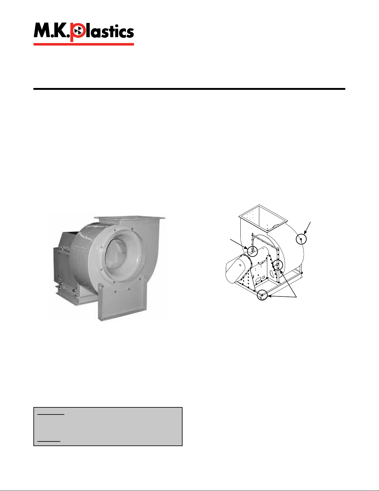
Handling
Fans are to be hoisted and moved by the lifting lugs provided
on the fan (see Figure 1). Location of lugs & brackets varies
by fan size and arrangement. Fans can also be hoisted with
slings placed around the fan housing. When a single hoist
is used, a “spreader” will keep the sling from slipping on the
housing. Large units may have lifting lugs or holes which
should be used only to stabilize the unit while using a sling to
support the weight.
Chain or wire slings should be well-padded where they
contact the fan as not to cause damage to the berglass
surface. Fans should never be lifted by the shaft, fan
housing, motor, belt guard, damper, weather hood, inlet &
outlet anges or any other accessories.
Lifting Lugs
Receiving and Inspection
All M.K. Plastics fans are carefully inspected before leaving
the factory. Compare all components with the bill of lading or
packing list to verify that the proper unit was received. Check
each unit for any damage that may have occurred in transit.
Mishandled units can void the warranty provisions. If units
are damaged in transit, it is the responsibility of the receiver
to make all claims against the carrier. M.K. Plastics is not
responsible for damages incurred during shipment.
WARNING
This unit has rotating parts. Safety precautions
should be exercised at all times during installation,
operation, and maintenance.
ALWAYS disconnect power prior to working on fan.
Lifting Lugs
Lifting Lugs
Figure 1.
Lifting Using the Lifting Lugs
Storage
If the unit cannot be installed and operated immediately,
precautions need to be taken to prevent deterioration of the
unit during storage. The user assumes responsibility of the
fan and accessories while in storage. M.K. Plastics will not be
responsible for damage during storage.
Store in a dry, protected area being sure fan shaft, bearings
and impeller are protected against dust and corrosion. If it
is necessary to store outdoors or within a building under
construction, special care must be taken to prevent moisture,
dirt or dust accumulation. Coat the shaft with grease or rust
preventative compound. Cover and seal bearings to prevent
entrance of contaminants. Impeller should be rotated at least
once a month to circulate the grease in bearings. If stored
outdoors, cover completely with a tarp or heavy plastic wrap.
Electrical connections and leads must be protected from
moisture. Block impeller to prevent natural rotation. Do not
allow material of any kind to be piled on top or inside of fan.
M.K. Plastics Corp. Montréal, Québec www.mkplastics.com Page. 1
Page 2
Pre-Installation
When the unit is removed from storage after a long duration,
all bearing grease should be purged and replenished with
fresh grease as per the lubrication decal. The motor should be
measured to verify that the resistance is still at a satisfactory
level compared to the value recorded prior to storage.
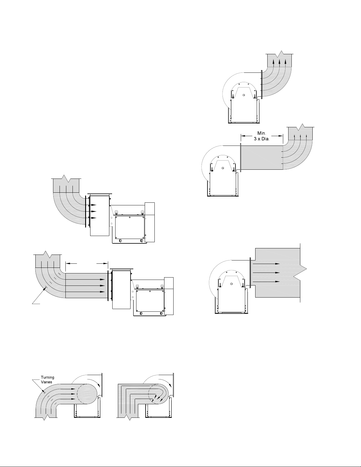
Inlet & Outlet Fan Installation
Efcient fan performance relies on the proper installation
of inlet and discharge ducts. Installations with poor inlet or
discharge congurations may result in reduced performance.
Restricted or unstable ow at the fan inlet can cause pre
rotation of incoming air or uneven loading of the fan wheel
resulting in increased system losses and sound levels.
Free discharge or turbulent ow in the discharge ductwork
will also result in system losses. Make sure the following
recommendations are followed.
Inlet Duct Turns
Installation of a duct turn or elbow too close to the fan inlet
reduces fan performance. To achieve full fan performance,
there should be at least three effective wheel diameters
between duct turns or elbows and the fan inlet.
Poor
Discharge Duct Turns
Where possible, allow minimum three duct diameters between
turns or elbows and fan outlet. Fan performance is reduced
when turns are made immediately off the fan discharge.
Poor
Good
Min.
3 x Dia.
Turning Vanes
Figure 2 - Inlet Ducting
Good
Inlet Spin
A common cause of reduced fan performance is inlet spin. To
prevent this occurring, it is good practice to use turning vanes
in the duct to reduce the effects.
Good Poor
Figure 3 - Inlet Spin
Figure 4 - Outlet Ducting
Free Discharge
Avoid a free discharge into the plenum. This will result in
lost efciency because it doesn’t allow for a static regain.
Figure 5 - Free Discharge
Fan Installation
Follow proper handling instructions given earlier.
• Move the fan to the nal mounting position.
• Remove skid, crates, and packing materials carefully.
• If supplied, place vibration pads or isolation base on
mounting bolts. Line up holes in fan base with bolts.
• Place fan on mounting structure. Carefully level utilizing
shims as required at all mounting hole locations. Bolt
down the unit.
• Any grout may now be used. Bolt the fan in position
before applying grout. Do not depend upon grout to
support rotating equipment.
• Continue with Operations Checklist.
Additional instructions may be given for some fan sizes,
components and accessories in the submittal.
M.K. Plastics Corp. Montréal, Québec www.mkplastics.com Page. 2
Page 3
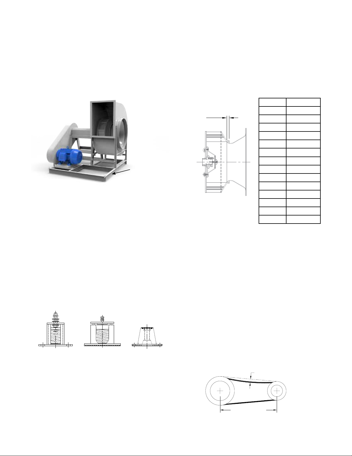
Isolation and Support Foundation
Essential to every DHK fan installation is a strong, level
foundation. A correctly designed concrete foundation with
a structural steel base or inertia base provides the best
means of supporting oor mounted units. Any foundation
size is determined by the fan arrangement, size, weight,
motor weight, position or fan orientation and location of the
installation. The weight of the foundation must be greater
than the weight of the fan and its motor. Roof or oor structure
supports should be per the structural engineer, in accordance
with load requirements and applicable building codes.
Isolation Base
Figure 5 - Isolation (Unitary) Base
Vibration Isolators
To prevent vibration and noise from being transferred to
the building, vibration isolators are recommended. Isolators
should be located between the fan system and the support
structure. M.K. Plastics supplies three main types of isolators
for FRP fans:
• Floor Mounted Seismically Restrained Spring Isolators
(1” to 4” deection)
• Floor Mounted Non-Restrained Housed Spring Isolators
(1” to 3” deection)
• Floor Mounted Rubber-In-Shear Isolators (rubber
mounts)
Refer to the M.K. Plastics submittal for isolator installation
and adjustment instructions. In applications where seismic
installation is required, refer to the M.K. Plastics submittal for
further details.
Seismically Restrained
Spring Isolator
Housed Spring Isolator Rubber-In-Shear
Isolator
Figure 6
Vibration Isolators (Typical)
Wheel-Inlet Overlap
Efcient performance is achieved by having the correct wheel
to inlet overlap and uniform radial gap. This should always be
veried before initial start-up and if possible after the fan has
been in operation for 24 hours.
The overlap is adjusted by loosening the wheel hub on the
shaft and moving the wheel to the correct position - refer to
Table 1. for values. A uniform radial gap (between the edge of
wheel inlet and edge of inlet cone) is achieved by loosening
the bolts on the inlet cone and centering it on the wheel. In
both cases, a trim balance maybe required.
Size Overlap
1225 7/16”
Overlap
Figure 7
Wheel/Inlet Overlap
1500 5/8”
1825 3/4”
2225 15/16”
2450 1”
2700 1-1/16”
3000 1-5/16”
3300 1-3/8”
3650 1-1/2”
4025 1-5/8”
4450 1-13/16”
4900 2”
5425 2-1/8”
6000 2-3/8”
Table 1
Wheel/Inlet Overlap
Drive Maintenance and Installation
V-belt drives need periodic inspection, retensioning, and
occasional belt replacement. When inspecting drives, look for
dirt buildup, burrs or obstructions that can cause premature
belt or drive replacement. If burrs are found, use ne emery
cloth or a stone to remove them. Be careful that dust does
not enter the bearings. Check sheaves for wear. Excessive
slippage of belts on sheaves can cause wear and vibration.
Replace worn sheaves with new ones. Carefully align
sheaves to avoid premature sheave failure.
Belt tension is determined by the sound the belts make
when the fan is rst started. Belts will produce a loud squeal
which dissipates after the fan is operating at full capacity. If
the belt tension is too tight or too loose, lost efciency and
possible damage can occur. The proper tension for operating
a V-belt is the lowest tension at which the belts will not slip
at peak load conditions. For initial tensioning, the proper belt
deection half-way between pulley centers is 1/60” for each
inch of belt span.
Deflection [inch]
After the fan, isolation base, and isolators are installed,
the entire assembly must be leveled. Position the level on
the isolation base, not the fan shaft, for proper leveling.
Additionally, the motor and fan shafts must be level and
parallel relative to each other for proper alignment.
M.K. Plastics Corp. Montréal, Québec www.mkplastics.com Page. 3
Belt Span [inch]
Figure 8 - Belt Tension
Page 4
Refer to the following procedure for belt tensioning -
C
1. Loosen motor plate adjustment bolts and move motor
plate in order that the belts can easily slip into the
grooves on the pulleys. Never pry, roll, or force the belts
over the rim of the pulley.
2. Adjust the motor plate until proper tension is reached.
For proper tension, a deection of approximately 1/60”
per inch of center distance should be obtained by rmly
pressing the belt. Refer to Figure 8.
3. Lock the motor plate adjustment nuts in place.
4. Ensure pulleys are properly aligned.
When replacing belts, replace the entire set. After initial
replacement and tensioning, recheck belt tension after a few
days. New belts require a break-in period. Never use belt
dressing on any belts.
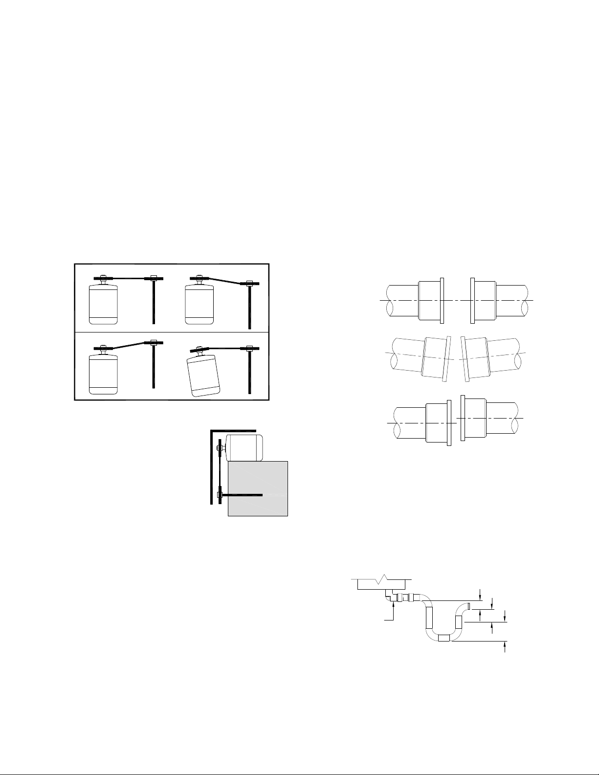
Drive Alignment
Pulley alignment is adjusted by loosening the motor pulley
setscrew and by moving the motor pulley on the motor shaft.
Fig. 9 illustrates correct and incorrect pulley alignment.
Correct Incorrect
Wheel and Shaft Maintenance
Periodically inspect the shaft and wheel for dirt buildup,
corrosion, and signs of excess stress or fatigue. Clean the
components. If the wheel is removed for any reason, make
sure that it is securely attached to the shaft before restarting
the fan.
Arrangement 8 Shaft Flexible Couplings
Coupling alignment should be checked after installation and
prior to start up. Alignment is set at the factory, but shipping,
handling, and installation can cause misalignment. Check
for misalignment between the coupling halves. Parallel
and angular misalignment and separation gap are shown
in Figure 11. Refer to coupling manufacturer’s installation
instructions for allowable misalignment and separation gap
tolerances. When correcting for misalignment using shims,
the shims should only be located under the motor. Do not
place shims under the shaft bearings. A dial indicator or
laser can be used for alignment where greater precision is
required. After aligning procedure, check for tightness of all
coupling component pieces and ensure that they are clean
from dirt and debris.
Separation
Incorrect Incorrect
Figure 9 - Pulley Alignment
A recommended method of inspecting
the pulley alignment is shown in
Figure 10. With the shorter leg of a
carpenter’s square or other straight
edge lying along the case of the
motor, adjust the position of the motor
pulley (or the motor) until the longer
leg of the square is parallel to the belt.
Motor Maintenance
The three basic rules of motor
maintenance are:
Figure 10
1. Keep the motor clean.
2. Keep the motor dry.
3. Keep the motor properly lubricated.
Blow dust off periodically (with low pressure air) to prevent
motor from overheating.
Some smaller motors are lubricated for life. Lubrication
requirements are normally attached to the motor. Use the
motor manufacturer’s recommendations for relubrication. If
this information is not available, the following schedule may
be used. Motors less than 10 HP running about eight hours a
day in a clean environment should be lubricated once every
ve years; motors 15 to 40 HP, every three years. For motors
in dusty or dirty environments or running 24 hours a day:
divide the service interval by 4. Do not over lubricate.
Angular
Misalignment
Parallel
Misalignment
Figure 11 - Flexible Couplings
Drainage Detail
All DHK fans come as standard with outlet drains due to the
possibility of water or condensation that may occur. Proper
disposal of water must occur by connection of drain outlet to
a drainage system (by others). Piping must have adequate
pitch for proper runoff and be supported (if needed) to prevent
the possibility of sagging and overow. The trap should be
lled before start-up.
A
Fan Drain
Dimension of A, B, C: Inches
Figure 12 - Drainage Detail
A: Must be greater than system static pressure.
B: Must be greater than 1/2 of the system static pressure.
C: 1” water seal.
B
M.K. Plastics Corp. Montréal, Québec www.mkplastics.com Page. 4
Page 5

Speed [rpm] 500 1000 1500 2000 2500 3000
Size
1225
1500
1825
2225
1225
6 6 5 3 3 2
1500
6 6 5 3 3 2
1825
6 6 5 3 3 2
2225
6 6 5 3 3 -
2450
6 4 4 3-1/2 2-1/2 -
2700
6 4 4 3-1/2 2-1/2 -
3000
5 4 3 2-1/2 - -
3300
5 4 3 2-1/2 - -
3650
5 4 3 - - -
4025
5 4 2-1/2 - - -
4450
4-1/2 3-1/2 2-1/2 - - -
4900
4-1/2 3-1/2 - - - -
5425
4-1/2 3-1/2 - - - -
6000
4-1/2 3-1/2 - - - -
Relubrication Schedule [Months]
For Bearings With No Grease Fittings
For Bearings With Grease Fittings
Relubrication is not required. Bearings are factory charged with the
correct amount of grease and do not require further grease charge.
Table 2 - Relubrication Schedule [Months]
Fan Bearing Lubrication
Proper lubrication of the fan drive bearings helps assure
maximum bearing life. DHK fans come with three types of
fan bearings:
1. Self-Lube pillow block ball bearings (1225-2225), which
do not require re-greasing. No grease ttings.
2. Air Handling Heavy Duty ball bearing pillow blocks
(1225-2225), which do require re-greasing. With grease
ttings - see schedule on Table 2.
3. Spherical split pillow block bearings (2450-6000), which
do require re-greasing through a grease tting on the
outer housing and should be lubricated by the schedule,
Table 2.
However, every installation is different and the frequency
of relubrication should be adjusted accordingly. On high
moisture applications, the lubrication frequency may need
to be doubled or tripled to adequately protect the bearings.
Double the relubrication frequency on fans with vertical
shafts.
Observation of the conditions of the grease expelled from the
bearings at the time of relubrication is the best guide as to
whether regreasing intervals and amount of grease added
should be altered.
Greases are made with different bases. There are synthetic
base greases, lithium base, sodium base, etc. Avoid mixing
greases with different bases. They could be incompatible
and result in rapid deterioration or breakdown of the grease.
All bearings are lled with a lithium-based grease before
leaving the factory. When the fans are started, the bearings
may discharge excess grease through the seals for a short
period of time. Do not replace the initial discharge because
leakage will cease when the excess grease has worked out.
Sometimes the bearings have a tendency to run hotter during
this period. There is no reason for alarm unless it lasts over
48 hours or gets very hot (over 200°F). When relubricating,
use a sufcient amount of grease to purge the seals. Rotate
bearings by hand during relubrication.
Table 2 is for shaft bearings on belt drive and direct drive
arrangement #8 fans, motor bearing lubrication should be per
the motor manufacturers instructions.
Suggested initial greasing interval - remove bearing cap
and observe condition of used grease after lubricating.
Adjust lubrication frequency as needed. Hours of operation,
temperature, and surrounding conditions will affect the
relubrication frequency required. ‘If bearings need to be re
packed, remove old grease, pack bearing full and ll housing
reservoirs on both sides of bearing to bottom of shaft.’
Lubricate with a multipurpose roller bearing NLGI No. 2 having
rust inhibitors and antioxidant additives, and a minimum oil
viscosity of 500 SSU at 100ºF. Some greases having these
properties are:
1. Shell - Alvania No. 2 Mobil
2. Mobilith AW2/Mobilith SHC100
3. Texaco - Premium RB2
4. American - Rykon Premium 2
Lubricate bearings prior to extended shutdown or storage
and rotate shaft monthly to aid corrosion protection.
Fan Bearing Replacement
Figure 13
Split Pillow Block
Figure 14
Solid Pillow Block
M.K. Plastics Corp. Montréal, Québec www.mkplastics.com Page. 5
Page 6

Removal of Wheel, Shaft & Bearings -
1. Mark the position on the shaft of both bearing races,
setscrews (if applicable) and the wheel and sheave. If
you are replacing the shaft as well, these marks will give
you reference.
2. Mark the location and orientation of the inlet cone and
sleeve to the casing and remove, this will give you
access to the wheel. Remove the drive sheave from the
shaft
3. Start wheel removal by unscrewing the front protective
cap and then the nut, washers and threaded stud
assembly that holds the cap to the fan shaft. The exposed
bushing has hex screws that secure the bushing to the
shaft; they are situated on the front face of the bushing.
Unscrew the hex screws, remove and screw back into
the other exposed holes of the bushing. By doing this
you are pushing the bushing out. Remove and then use
a 2-jaw puller to extract the bushing if needed. When the
bushing is out, the wheel and hub assembly can now be
removed from the fan shaft. Note: DHK 1225 to 1500
sizes do not have bushings, the wheel is held in place to
the shaft with the threaded rod assembly only.
4. Unbolt the bearing housing hold-down bolts and remove
the shaft and bearings as one unit. Keep any existing
shims in place.
5. Unbolt the top housing section and remove the bearing
assemblies from the shaft. A suitable puller may be
required, or tap on the bearing with a wood block and
hammer to remove. If the bearings are attached with
set screws, unscrew and slide the assembly off as one
piece.
6. If the existing shaft is being used, check the shaft for
nicks, burrs and damage. Remove any anti-corrosion
coating with a suitable degreaser and wipe clean.
Bearing Replacement [Split Housing Bearings With
Adapter Sleeves] -
1. Split pillow block bearings come in kits with bearings,
adapter sleeve, locknut, lock washer and xing rings for
the rear xed bearing. NOTE: replacement bearings will
be shipped temporarily assembled on a shaft.
2. Remove the top half of the bearing housing to expose
the bearing seat.
3. Place the lower half of the bearing housings in position
on the stand and tighten the xing bolts.
4. Spherical split pillow block bearings use synthetic rubber
seals that come in split (half) sections. One half should
be inserted into the lower bearing housing on both sides
and some grease applied prior to the bearing assembly.
5. Place the bearings in the lower half of the housings with
the larger sides of the bores facing towards the shaft
ends.
6. Slide the adapter sleeves through the bearings, ensuring
that the threads are facing each other.
7. Install the lock washers on the adapter sleeves with
inner prong of washer in a slot on the adapter sleeve.
Install the locknut on both bearings with the chamfered
face facing the bearing, but do not tighten.
8. Slide shaft through both bearing assemblies. If the
bearing locks to the shaft, tap gently on the adapter
sleeve to loosen.
9. To hold the shaft in place during wheel mounting, clamp
the sheave end of the shaft to the edge of the stand.
10. Install the wheel and bushing on the shaft. Install the inlet
cone in its original location. Position the wheel correctly
by moving the shaft axially in the bearing assemblies.
11. Install xing rings on the rear bearing (closest to sheave).
Move shaft axially so that the xing ring may be inserted
between housing shoulder and bearing outer ring.
12. Tighten locknuts to fasten the bearings to the shaft,
using a spanner. While tightening, regularly measure
the internal bearing clearance between the most vertical
unloaded roller and outer ring with a feeler blade. When
required clearance is obtained (check table), tighten
locknut until the closest washer tab meets a slot on the
locknut.
13. Fill the lower housings with grease until the rollers are
covered.
14. Carefully align the top part of the housing with the dowel
pins and tighten bolts, ensuring that the upper seals
are in place. Make sure that the split housing is paired
only with its original top half, as these parts are not
interchangeable from one housing to another.
Bearing Replacement [Closed Housing Bearings With
Setscrews] -
1. Making sure that the set screws are not protruding from
the inner bearing rings, slide the bearings directly onto
the shaft. If using an old shaft, make sure the bearings
are not mounted on a worn section. Tapping the inner
ring face with a soft driver might be required.
2. The outer ring of the bearing is spherical and swivels
in the housing to compensate for misalignment. Secure
the housing to the stand with the xing bolts, but do not
fully tighten.
3. Install the wheel on the shaft. Install the inlet cone in its
original location. Position the wheel correctly by moving
the shaft axially in the bearing assemblies.
4. Tighten the setscrews on the bearings to secure the
shaft. Refer to torque chart on Page 7.
5. Rotate the shaft by hand to allow the bearing outer rings
to nd their center of free movement.
Test Run -
1. Re-install the sheave and adjust the belt tension.
2. Test run and retighten all setscrews and xing bolts; trim
balance as necessary.
Changing Shaft Speed
All belt driven fans with motors up to and including 5 HP
are equipped with variable pitch pulleys. To change the fan
speed, perform the following:
1. Loosen setscrew on driver (motor) pulley and remove
key, if equipped.
2. If the pulley has multiple grooves, all must be adjusted
to the same width.
3. After adjustment, inspect for proper belt tension.
4. To reduce speed, open the pulley in order that the belt
rides deeper in the groove (smaller pitch diameter).
5. To increase speed, close the pulley so that the belt rides
higher in the groove (larger pitch diameters). Make sure
the maximum fan RPM and motor HP is not reached.
M.K. Plastics Corp. Montréal, Québec www.mkplastics.com Page. 6
Page 7

Size
Set Screw /
Bolt Torque
Size
Pillow Block
Bearing
Set Screw /
Bearing Cap
Bolt Torque
Mounting Bolt
304 SS Bolt
Torque
316 SS Bolt
Torque
1225 RHP, MP1 60 in-lbs 3/8-16UNC, 1.75L 236 in-lbs 247 in-lbs
1500 RHP, MP1 60 in-lbs 3/8-16UNC, 1.75L 236 in-lbs 247 in-lbs
1825 RHP, MP1-7/16 110 in-lbs 1/2-13UNC, 2.25L 517 in-lbs 542 in-lbs
2225 RHP, MP1-7/16 110 in-lbs 1/2-13UNC, 2.25L 517 in-lbs 542 in-lbs
2450 NSK,SNN,1-11/16 389 in-lbs 1/2-13UNC, 1.75L 517 in-lbs 542 in-lbs
2700 NSK,SNN,1-11/16 389 in-lbs 1/2-13UNC, 2.25L 517 in-lbs 542 in-lbs
3000 NSK,SNN,2-3/16 673 in-lbs 5/8-11UNC, 2.5 L 1110 in-lbs 1160 in-lbs
3300 NSK,SNN,2-3/16 673 in-lbs 5/8-11UNC, 2.5 L 1110 in-lbs 1160 in-lbs
3650 NSK,SNN,2-3/16 673 in-lbs 5/8-11UNC, 2.5 L 1110 in-lbs 1160 in-lbs
4025 NSK,SNN,2-7/16 673 in-lbs 5/8-11UNC, 2.75L 1110 in-lbs 1160 in-lbs
4450 NSK,SNN,2-15/16 1682 in-lbs 3/4-10UNC, 3 L 1530 in-lbs 1582 in-lbs
4900 NSK,SNN,2-15/16 1682 in-lbs 3/4-10UNC, 3 L 1530 in-lbs 1582 in-lbs
5425 NSK,SNN,3-7/16 3275 in-lbs 1-8UNC, 3.75L 3400 in-lbs 3595 in-lbs
6000 NSK,SNN,3-7/16 3275 in-lbs 1-8UNC, 3.75L 3400 in-lbs 3595 in-lbs
MSK
Bushing
Cap Screw Torque
H 1/4 x 3/4 95 in-lbs
P 5/16 x1 192 in-lbs
Q 3/8 x 1-1/4 348 in-lbs
R 3/8 x 1-3/4 348 in-lbs
S 1/2 x 2-1/4 840 in-lbs
U 5/8 x 2-3/4 1680 in-lbs
W 3/4 x 3 3000 in-lbs
P1-P3 5/16-18 UNC 80 in-lbs
Q1-Q3 3/8-16 UNC 143 in-lbs
Bushing Tightening for Aluminum Hub
304 SS Bolt
Torque
316 SS Bolt
Torque
1225 RHP, MP1 60 in-lbs 3/8-16UNC, 1.75L 236 in-lbs 247 in-lbs
1500 RHP, MP1 60 in-lbs 3/8-16UNC, 1.75L 236 in-lbs 247 in-lbs
1825 RHP, MP1-7/16 110 in-lbs 1/2-13UNC, 2.25L 517 in-lbs 542 in-lbs
2225 RHP, MP1-7/16 110 in-lbs 1/2-13UNC, 2.25L 517 in-lbs 542 in-lbs
2450 NSK,SNN,1-11/16 389 in-lbs 1/2-13UNC, 1.75L 517 in-lbs 542 in-lbs
2700 NSK,SNN,1-11/16 389 in-lbs 1/2-13UNC, 2.25L 517 in-lbs 542 in-lbs
3000 NSK,SNN,2-3/16 673 in-lbs 5/8-11UNC, 2.5 L 1110 in-lbs 1160 in-lbs
3300 NSK,SNN,2-3/16 673 in-lbs 5/8-11UNC, 2.5 L 1110 in-lbs 1160 in-lbs
3650 NSK,SNN,2-3/16 673 in-lbs 5/8-11UNC, 2.5 L 1110 in-lbs 1160 in-lbs
4025 NSK,SNN,2-7/16 673 in-lbs 5/8-11UNC, 2.75L 1110 in-lbs 1160 in-lbs
4450 NSK,SNN,2-15/16 1682 in-lbs 3/4-10UNC, 3 L 1530 in-lbs 1582 in-lbs
4900 NSK,SNN,2-15/16 1682 in-lbs 3/4-10UNC, 3 L 1530 in-lbs 1582 in-lbs
5425 NSK,SNN,3-7/16 3275 in-lbs 1-8UNC, 3.75L 3400 in-lbs 3595 in-lbs
6000 NSK,SNN,3-7/16 3275 in-lbs 1-8UNC, 3.75L 3400 in-lbs 3595 in-lbs
Pillow Block
Bearing
Bearing Cap
Mounting Bolt
304 SS Bolt
Torque
316 SS Bolt
Table 3 - Fan Bearing Torque
Tapered
Bushing
QT 1/4-20UNC 108 in-lbs
JA No.10-24UNC 60 in-lbs
SH-SDS-SD 1/4-20UNC 108 in-lbs
SK 5/16-18UNC 180 in-lbs
SF 3/8-16UNC 360 in-lbs
E 1/2-13UNC 720 in-lbs
F 9/16-12UNC 1320 in-lbs
J 5/8-11UNC 1620 in-lbs
M 3/4-10UNC 2700 in-lbs
N 7/8-9UNC 3600 in-lbs
P 1-8UNC 5400 in-lbs
W 1-1/8-7UNC 7200 in-lbs
S 1-1/4-7UNC 9000 in-lbs
Cap Screw Torque
MSK
Bushing
Bushing Tightening for Aluminum Hub
Cap Screw Torque
H 1/4 x 3/4 95 in-lbs
P 5/16 x1 192 in-lbs
Q 3/8 x 1-1/4 348 in-lbs
R 3/8 x 1-3/4 348 in-lbs
S 1/2 x 2-1/4 840 in-lbs
U 5/8 x 2-3/4 1680 in-lbs
W 3/4 x 3 3000 in-lbs
P1-P3 5/16-18 UNC 80 in-lbs
Q1-Q3 3/8-16 UNC 143 in-lbs
Table 4 - Bushing and Pulley Torque
Torque
F Ensure belt touches only the pulleys.
F Ensure fan and ductwork are clean and free of debris.
F Inspect wheel-to-inlet clearance.
F Close and secure all access doors.
F Restore power to the fan.
Start Up
Turn the fan on. In variable speed units, set the fan to its
lowest speed and inspect for the following:
F Direction of rotation.
F Excessive vibration.
F Unusual noise.
F Bearing noise.
F Improper belt alignment or tension (listen for squealing).
F Improper motor amperage or voltage.
If a problem is discovered, immediately shut the fan off. Lock
out all electrical power and check for the cause of the trouble.
See Troubleshooting.
Inspection
Inspection of the fan should be conducted at the rst
30 minute, 8 hour and 24 hour intervals of satisfactory
operation. During the inspections, stop the fan and inspect.
F 30 Minute Interval: Inspect bolts, setscrews, and motor
mounting bolts. Adjust and tighten as necessary.
F 8 Hour Interval: Inspect belt alignment and tension.
Adjust and tighten as necessary.
F 24 Hour Interval & 30 Days: Inspect belt tension. Adjust
and tighten as necessary.
Grounding Straps
Static Grounding Strap
If supplied with a Graphite Liner, a
grounding strap is provided on the
bottom of the scroll housing for the
removal of static electricity. This strap
must be connected to the building
electrical grounding circuit or the
roof steel structure. If an Aegis shaft
grounding ring is supplied on the
motor, the motor support stand should
also be grounded.
Operational Checklist
Final Installation
F Inspect fasteners and setscrews, particularly fan
mounting and bearing fasteners, and tighten according
to the recommended torque shown in Tables 3 & 4.
F Inspect for correct voltage with voltmeter.
F Ensure all accessories are installed.
Pre-Start Checks
F Shut off all primary and secondary power sources.
F Ensure fasteners and setscrews are tightened.
F Inspect belt tension and pulley alignment.
F Inspect motor wiring.
Figure 15
Grounding Strap
General Fan Maintenance
WARNING
Disconnect and secure to the ‘Off’ position all electrical power to the fan prior to inspection and servicing.
Failure to comply with this safety precaution could
result in serious injury or death.
Once the unit has been put into operation, a routine
maintenance schedule should be set up to accomplish the
following:
1. Lubrication of bearings and motor.
2. Wheel, housing, bolts and set screws on the entire fan
should be checked for tightness.
3. Any dirt accumulation on the wheel or in the housing
should be removed to prevent unbalance and possible
damage.
4. Isolation bases should be checked for freedom of
movement and the bolts for tightness. Springs should be
checked for breaks and fatigue. Rubber isolators should
be checked for deterioration.
5. Inspect fan impeller and housing looking for fatigue,
corrosion or wear.
6. Check V-belt drives on a regular basis for wear, tension,
alignment and dirt accumulation.
7. If drive belts have been replaced, new belts will stretch.
Belt tension needs to be checked & adjusted after 1
week, and again after 30 days of operation. Refer to
Figure 8. on Page 3 for details.
M.K. Plastics Corp. Montréal, Québec www.mkplastics.com Page. 7
Page 8

Troubleshooting
Excessive Noise or Vibration
• Damaged wheel.
• Wheel rubbing inlet; adjust wheel or inlet cone.
• Verify wheel balance, rebalance if necessary.
• Belts misaligned.
• Belts too loose; worn or oily belts.
• Loose fasteners.
• Speed too high.
• Incorrect direction of rotation. Make sure the fan rotates in same direction as the arrows on the motor or belt
drive assembly.
• Bearing collars or hardware loose.
• Bearings need lubrication or replacement.
• Debris in impeller; clean all dirt off wheel, check wheel balance and rebalance if necessary.
• Fan surge.
• Check alignment of shaft and motor drives.
Low Volume or Pressure
• Incorrect direction of rotation. Make sure the fan rotates in same direction as the arrows on the motor or belt
drive assembly.
• Poor fan inlet or outlet conditions. There should be a straight clear duct at the inlet or outlet.
• Improper wheel alignment.
• Check duct system, see Page 2. For recommendations.
Motor Problems (Overheating)
• Motor improperly wired.
• Incorrect direction of rotation. Make sure the fan rotates in same direction as the arrows on the motor or belt
drive assembly.
• High horsepower; resize the ductwork. Check proper operation of face and bypass dampers. Check lters
and access doors.
• Cooling air diverted or blocked.
• Improper inlet clearance.
• Incorrect fan speed.
• Incorrect voltage.
Bearing Problems (Overheating)
• Improper bearing lubrication; check for excessive or insufcient grease in bearings.
• Excessive belt tension.
• Check for bent shaft.
• Align bearings.
M.K. Plastics Corp. Montréal, Québec www.mkplastics.com Page. 8
Page 9

DHK - Parts List - Belt Drive (Arrangement #1)
5
6
7
8
9
1234
15
16
Item No. Item Description
1 Inlet Sleeve
2 Inlet cone
3 Impeller
4 Fan Casing
5 Bearing
6 Shaft
7 Shaft / Bearing Guard
8 Pulleys
9 Belts
10 Belt Guard
11 Motor Base
12 Motor
13 Unitary Base (Standard)
14 Motor Cover (Optional)
15 Control Damper
16 Gravity Backdraft Damper
13 14
1110
12
M.K. Plastics Corp. Montréal, Québec www.mkplastics.com Page. 9
Page 10

DHK - Parts List - Belt Drive (Arrangement #10)
56
7
10
8
9
11
1234
14
15
12
Item No. Item Description
1 Inlet Sleeve
2 Inlet cone
3 Impeller
4 Fan Casing
5 Shaft
6 Bearing
7 Shaft / Bearing Guard
8 Pulleys
9 Belts
10 Motor
11 Belt Guard
12 Motor Base
13 Unitary Base (Optional)
14 Control Damper
15 Gravity Backdraft Damper
13
M.K. Plastics Corp. Montréal, Québec www.mkplastics.com Page. 10
Page 11

DHK - Parts List - Direct Drive
5
6
1
(Arrangement #4)
12
7
4
11
10
6
7
89
3
2
5
(Arrangement #8)
Item No. Item Description
1 Inlet Sleeve
2 Companion Flange
3 Inlet Cone
4 Impeller
5 Fan Casing
6 Motor
7 Unitary Base (Standard)
8 Shaft / Bearing Guard
9 Bearings
10 Coupling
11 Shaft Guard
12 Motor Cover (Optional)
M.K. Plastics Corp. Montréal, Québec www.mkplastics.com Page. 11
Page 12

Warranty
M.K. Plastics will not be responsible for damage to equipment or materials through improper installation, storage, improper
servicing, or through attempts to operate it in excess of its rated capacity or recommended use, intentional or otherwise. We will
not be responsible for consequential damage.
Based on the fact that M.K. Plastics has no direct control over the actual handling and use of its products in the eld, M.K.
Plastics does not assume any liability for any loss to the customer or any personnel or any physical damages that are claimed
by anyone due to a failure or cause attributed to the use of its products. In no event shall M.K. Plastics be responsible for
consequential damages of any such defective material or workmanship, including but not limited to the buyer’s loss of material
or prot, increase expense of operation, downtime or reconstruction of the work and in no event shall M.K. Plastics obligation
under this warranty exceed the original contract price of the defective item.
M.K. Plastics warrants its equipment, products and parts, to be free from defects in workmanship and material under normal
use and service for one (1) year after delivery to the rst user. Our obligation under this warranty being limited to repairing or
replacing, at our option, without cost at our factory any part, or parts which shall, within such warranty period, be returned to us
with transportation charges prepaid, and which our examination shall disclose to our satisfaction to have been defective.
M.K. Plastics will not be responsible for the cost of removal of a defective product or parts or the installation of a replaced product
or parts, or for costs due for its removal, crating or shipping.
On account of variables including but not limited to, vibration, system noise characteristics, motor overloading or change in
voltage condition, the specics of customer application of equipment or other system conditions, M.K. Plastics does not expressly
warrant its equipment for any specic purpose.
The customer and its agents are responsible for the selection and application of M.K. Plastics products, including their tness
for the purpose and performance intended. Consequently, the customer on behalf of its agents assumes all liability related to the
use/misuse, application and selection of the M.K. Plastics Products.
Bulletin 40-02-June 2013
CORPORATION
SERVING THE NEEDS OF MODERN INDUSTRY
M.K. Plastics Corp. Montréal, Québec www.mkplastics.com Page. 12
4955 de Courtrai Ave., Montréal, Québec, H3W 1A6 ● TEL: (514) 871-9999
Trimex Building, Route 11, Mooers, N.Y., 12958 ● TEL: (888) 278-9988
FAX: (514) 871-1753
Email: mkfans@mkplastics.com
 Loading...