

MKN FKECOD615, FlexiCombi MagicPilot Series, FKECOD121, FKECOD621, FKECOD215 Installation Instructions Manual
...Page 1
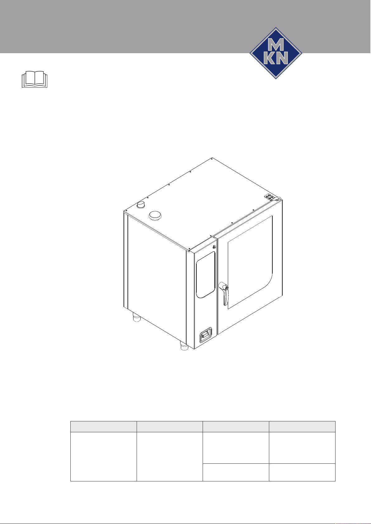
Read the operating instructions prior to
commissioning
Installation instructions
Combisteamer
Unit Type of energy Unit type Model
FlexiCombi MagicPilot Electric Countertop unit FKECOD615
Translation from the original document • 10013865-0AIDE-B • 14/10/2016
FKECOD621
FKECOD115
FKECOD121
Floor-standing unit FKECOD215
FKECOD221
10013865-0AIBE-B en-GB
Page 2

Manufacturer
MKN Maschinenfabrik Kurt Neubauer GmbH & Co. KG
Halberstädter Strasse 2a
38300 Wolfenbüttel
Germany
Phone +49 5331 89-0
Fax +49 5331 89-280
Internet www.mkn.eu
Copyright
All rights to text, graphics and pictures in this documentation are held by MKN Maschinenfabrik Kurt
Neubauer GmbH & Co. KG. Distribution or duplication is only permitted with the prior written consent
of MKN.
Copyright by MKN Maschinenfabrik Kurt Neubauer GmbH & Co. KG.
2 Installation instructions
Page 3

Directory of contents
1Introduction......................................................................... 5
1.1About this manual ............................................................................ 5
1.1.1Explanation of signs .................................................................................. 6
1.2Use of the unit................................................................................... 7
1.3Warranty............................................................................................ 7
2Safety information.............................................................. 8
3Description of the unit ..................................................... 10
3.1Overview of the unit ....................................................................... 10
3.2Planning drawing............................................................................ 12
3.3Equipment and connection data................................................... 13
4Transporting the unit ....................................................... 18
4.1Transporting the unit to the installation site ............................... 18
4.2Unpacking the unit ......................................................................... 19
5Setting up the unit............................................................ 20
5.1Maintaining minimum clearances................................................. 21
5.2Lifting the unit off the pallet .......................................................... 22
5.3Setting up the unit on the equipment legs................................... 22
5.4Setting up the unit on a base frame.............................................. 23
5.4.1Installing the support rack ....................................................................... 24
5.5Aligning the unit ............................................................................. 24
5.5.1Aligning countertop unit........................................................................... 24
5.5.2Aligning floor-standing units .................................................................... 24
6Connecting the unit.......................................................... 26
6.1Opening and closing the housing................................................. 26
6.1.1Removing and attaching side wall........................................................... 26
6.2Making the power connection....................................................... 27
6.2.1Matching the unit to the connection voltage ............................................ 29
6.2.2Connecting the power connection cable ................................................. 31
6.2.3Connecting the power optimisation system............................................. 32
6.2.4Connecting to the potential equalisation circuit ....................................... 33
6.3Connecting the kitchen management system ............................. 33
6.4Making the basic control setting................................................... 35
6.4.1Changing the basic control setting .......................................................... 35
6.5Making the water connection ........................................................ 36
6.5.1Connecting the tap water connection line ............................................... 37
6.5.2Connecting softened tap water to both connections ............................... 38
6.6Making the wastewater connection .............................................. 39
6.6.1Connecting the wastewater line to a permanent connection................... 39
6.7Making the exhaust air connection .............................................. 40
6.7.1Connecting the exhaust air line ............................................................... 40
10013865-0AIBE-B
3Installation instructions
Page 4

Directory of contents
7Testing the function ......................................................... 41
7.1Checking the controls.................................................................... 41
7.2Checking the monitoring of the cooking zone door ................... 42
7.3Running the self-diagnosis ........................................................... 42
8Putting the unit into service ............................................ 43
8.1Filling out the Commissioning report........................................... 43
4 Installation instructions
10013865-0AIBE-B
Page 5

1 Introduction
1.1 About this manual
Introduction
The instruction manual is part of the unit and contains information on
safe installation of the unit.
Observe and adhere to the following instructions:
• Read the instruction manual in its entirety prior to installation.
• Make the instruction manual available to the installer at the
operating site at all times.
• Preserve the installation manual throughout the service life of the
unit.
• Insert any supplements from the manufacturer.
• Pass on the installation manual to any subsequent operator of the
unit.
Target group The target group for the installation manual is trained technical
personnel that is familiar with installing and operating the unit.
Figures All figures in this manual are intended as examples. Discrepancies
between these and the actual unit can arise.
10013865-0AIBE-B
5Installation instructions
Page 6

Introduction
1.1.1 Explanation of signs
DANGER
Imminent threat of danger
Failure to comply will lead to death or very severe injuries.
WARNING
Possible threat of danger
Failure to comply can lead to death or very severe injuries.
CAUTION
Dangerous situation
Failure to comply can lead to slight or moderately severe
injuries.
ATTENTION
Physical damage
Failure to comply can cause physical damage.
Notes for better understanding and operation of the unit.
Symbol / sign Meaning
• Listing of information.
Action steps, which can be performed
in any sequence.
1.
2.
Action steps, which must be performed
in the specified sequence.
Result of an action performed or
additional information about it.
6 Installation instructions
10013865-0AIBE-B
Page 7

1.2 Use of the unit
1.3 Warranty
Introduction
This unit is intended to be used solely for commercial purposes,
particularly in commercial kitchens.
The use of the unit is prohibited in the following countries:
• USA
• Canada
The warranty is void and safety is no longer assured in the event of:
• Improper conversion or technical modifications of the unit,
• Improper use,
• Incorrect startup, operation or maintenance of the unit,
• Problems resulting from failure to observe these instructions.
10013865-0AIBE-B
7Installation instructions
Page 8

Safety information
2 Safety information
The unit complies with applicable safety standards. Residual risks
associated with operation or risks resulting from incorrect operation
cannot be ruled out and are mentioned specifically in the safety
instructions and warnings.
The installer must be familiar with regional regulations and observe
them.
The installer must observe the safety instructions in these mounting
instructions and in the "Safety information" chapter of the operating
instructions.
Ensuring conformity with
standards
Improper installation Risk of property damage and personal injury from improper
Transportation and storage Risk of personal injury and property damage from improper
Observe applicable international, European and national laws,
regulations, standards and directives for the unit when transporting,
setting up and connecting it.
installation
• Install the unit only as specified in these installation instructions.
• Do not add anything to the unit or modify the unit.
• Use only original spare parts.
transportation and improper storage
• Store the unit in a dry, frost-free environment.
• Observe the safety regulations for the lifting gear used.
• Attach the unit to the lifting gear securely during transport and
setup, and prevent it from dropping.
• Transport the unit in an upright position, do not tilt or stack.
• Pay attention to protruding parts when transporting the unit
without packaging.
Fire prevention Risk of fire from combustible surfaces
• Observe general fire prevention regulations.
Organisational measures Risk of property damage and personal injury from lack of
organizational measures
• Identify hazard areas when transporting, setting up and
connecting the unit.
• Prior to starting the installation work, notify any operators present
about the procedure.
• Prior to starting the installation work, discuss how to behave in an
emergency.
• Use equipment and protective gear suitable for the activity.
• Brace housing components to prevent them from falling over and
dropping.
8 Installation instructions
10013865-0AIBE-B
Page 9

Setup Risk of property damage and personal injury from improper
setup
• Ensure that the installation area has adequate load-bearing
capacity.
• Wear safety shoes and protective gloves.
Electrical connection Risk of fire from improper connection
• Observe applicable regional regulations of the electrical utility.
• Ensure that only electricians licensed by the electric utility connect
the unit.
• Ensure that the electrical system is earthed by a protective
earthing conductor.
• Note the information on the nameplate.
Risk of electric shock from live components.
• Prior to working on the electrical system, switch off the unit,
disconnect the electrical system from the mains and prevent
power from being switched on again. Check to ensure absence of
voltage.
Safety information
• Use only insulated tools.
Risk of electric shock
• The unit must be incorporated into the potential equalisation circuit
through use of the specified minimum wire sizes.
Unit on casters Risk of a line breaking if subjected to high tensile load
• Secure the unit with a chain as a strain relief for the power
connection at the installation site so that no tensile load is applied
to the power connection if the unit is moved.
Commissioning Risk of property damage and personal injury from improper
commissioning
• Read the operating instructions prior to commissioning. Observe
the safety instructions in this installation manual and in the "Safety
information" chapter of the operating instructions.
• Put the unit into service only after a successful function test
following assembly.
• Put the unit into service only after it has reached room
temperature.
10013865-0AIBE-B
• Observe the units during operation.
9Installation instructions
Page 10
Description of the unit
s
r
q
p
o
n
m
l
k
j
i h g f
e
d
c
b
a
3 Description of the unit
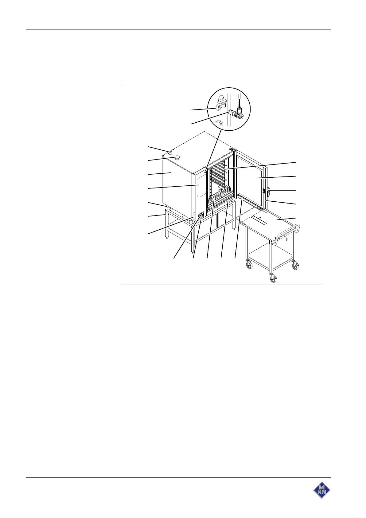
3.1 Overview of the unit
Image: Unit with tray rack trolley
a Tray rack k Nameplate
b Insulated window l Base frame (optional)
c Door handle m Equipment leg
d Cooking zone door n Control unit
e Tray rack trolley (optional) o Housing
f Steam drain channel, door p Air inlet
g Steam drain channel, unit q Steam outlet
h Guide rail for tray rack (optional) r Core temperature sensor
(optional)
i USB port (covered) s Connection for core temperature
sensor (optional)
j Hand shower (optional)
10013865-0AIBE-B
10 Installation instructions
Page 11
Description of the unit
a
d
e
c
b
k
j
i h g f
q
p
o
n
m
l
r
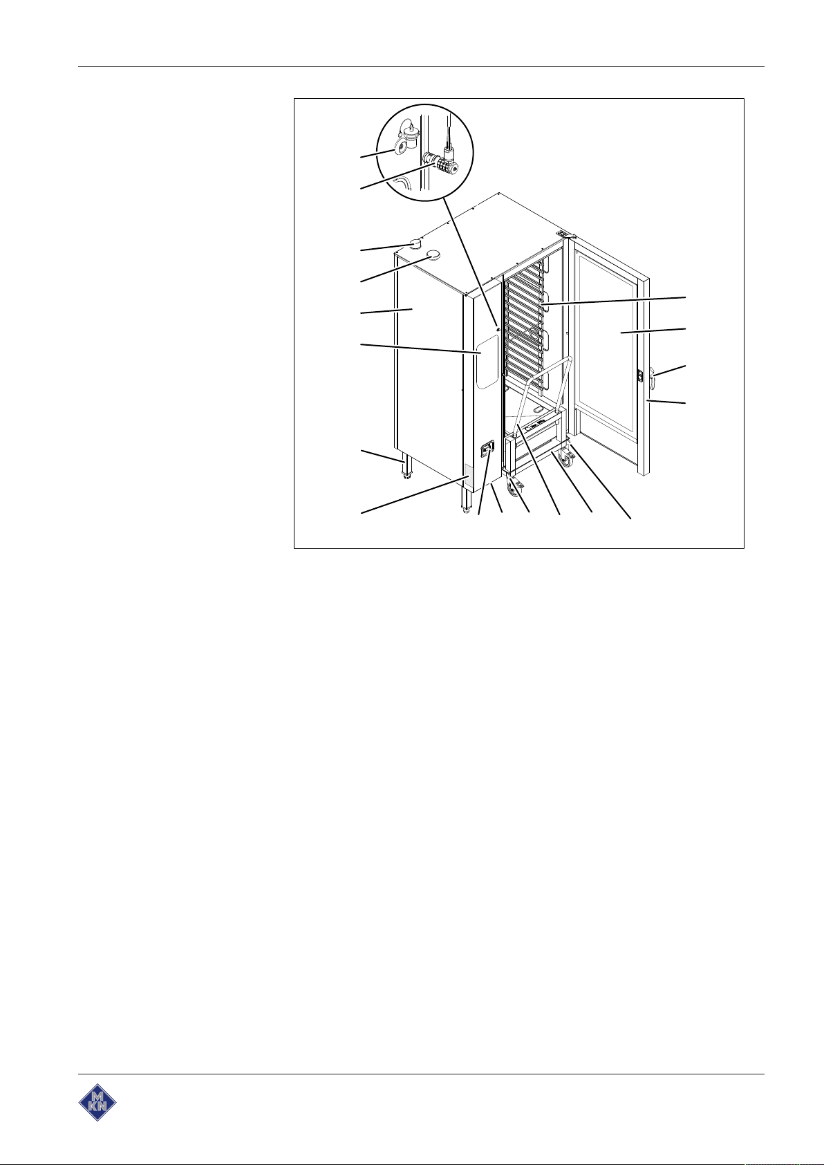
Image: Unit with tray trolley
a Tray rack j Hand shower
b Insulated window k Nameplate
c Door handle l Equipment leg
d Cooking zone door m Control unit
e Guide rail (right) n Housing
f Tray trolley o Air inlet
g Push handle p Steam outlet
h Guide rail (left) q Core temperature sensor
(optional)
i USB port (covered) r Connection for core temperature
sensor (optional)
10013865-0AIBE-B
11Installation instructions
Page 12
Description of the unit
F
BA
C
D
E
H
G
A
H
B C D
E
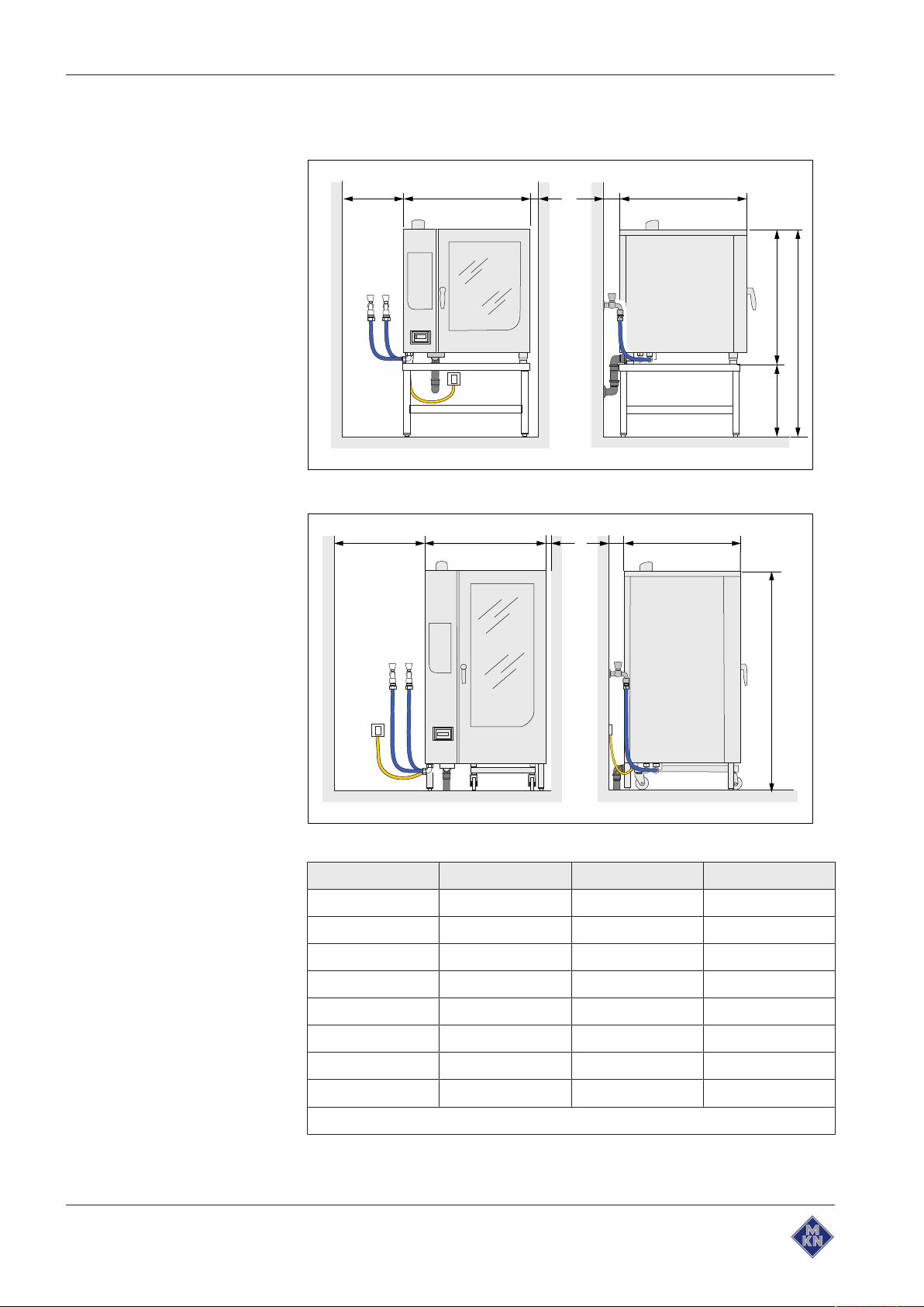
3.2 Planning drawing
Image: Size 6XX and 1XX
Image: Size 2XX
Size 615, 621 115, 121 215, 221
A 50 50 50
B 997 997 1075
C 50 50 50
D 50 50 50
12 Installation instructions
E 799 799 813
F 790 1060 ---
G 850 580 ---
H 1640 1640 1960
All dimensions in mm
10013865-0AIBE-B
Page 13
Description of the unit
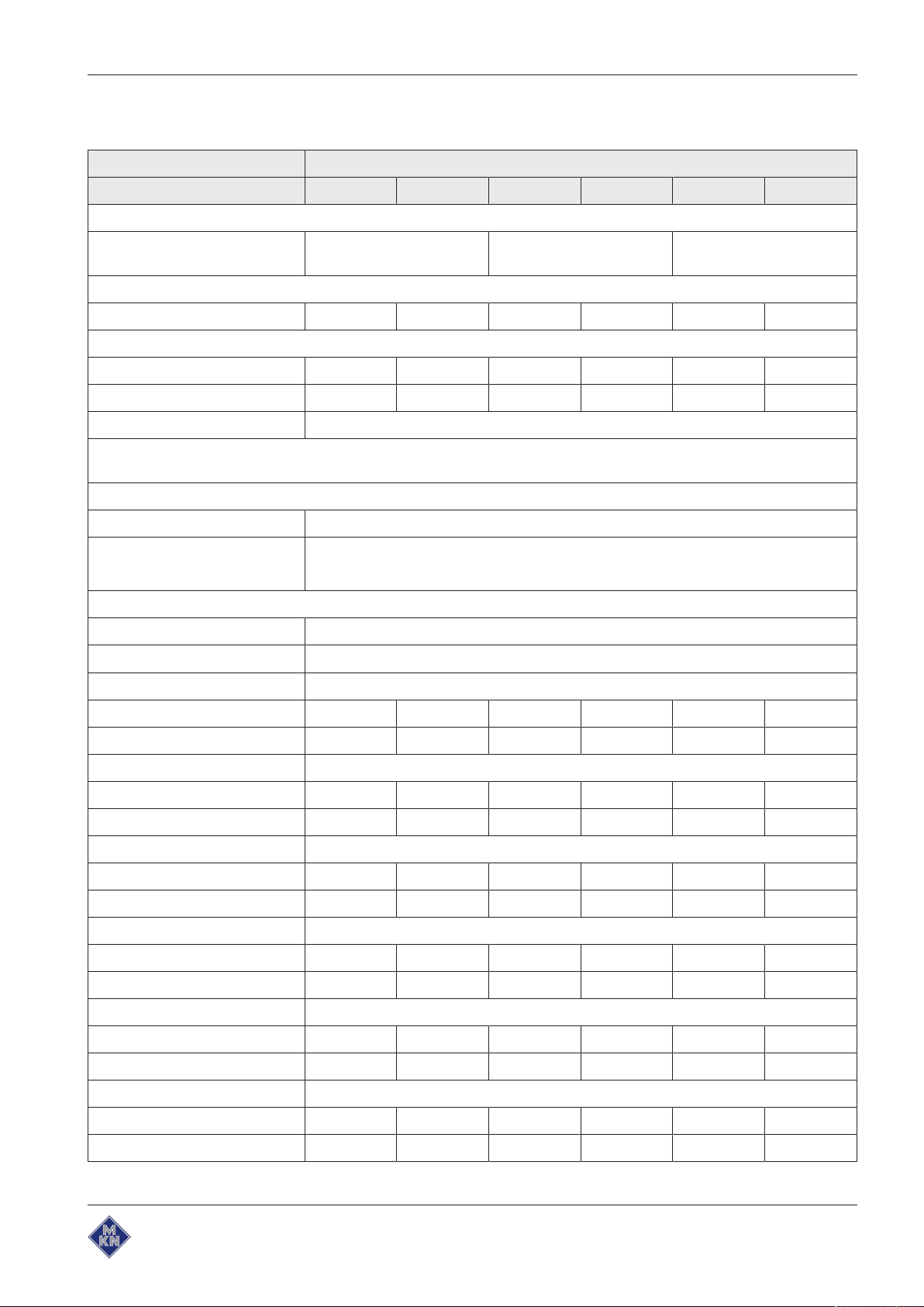
3.3 Equipment and connection data
Model: FKECOD
Size 615 621 115 121 215 221
Dimensions
Unit
Length x Width x Height (mm)
Weight
(kg) unit 120 125 140 145 305 313
Emissions
Latent heat (W) 1780* 3670* 2750* 5400* 5510* 10200
Sensible heat (W) 1190 2450 1840 3600 3670 7100
Noise level (db(A)) < 70
* The stated value is reduced by 80% when operating with a condensation hood; the sensible heat is increased by the
amount of the reduction.
Operating environment
Temperature (°C) 5 — 40
Relative humidity (%)
Non-condensing
Power connection
Protection class IPX5, IPX6 (optional)
Type of connection 3PE / AC 50/60Hz, 3NPE / AC 50/60Hz
Voltage (V) 200
997 x 799 x 790 997 x 799 x 1060 1075 x 813 x 1960
95
Connected load (kW) 10.1 16.3 14.7 25.5 29.4 50.9
Fuse (A) 3 x 35 3 x 50 3 x 50 3 x 80 3 x 100 3 x 180
Voltage (V) 208
Connected load (kW) 10.2 17.4 15.7 27.3 31.4 54.6
Fuse (A) 3 x 35 3 x 50 3 x 50 3 x 80 3 x 100 3 x 180
Voltage (V) 220
Connected load (kW) 11.6 19.7 17.7 30.8 35.4 61.4
Fuse (A) 3 x 35 3 x 63 3 x 63 3 x 100 3 x 125 3 x 180
Voltage (V) 230
Connected load (kW) 12.6 21.4 19.3 33.6 38.6 67
Fuse (A) 3 x 35 3 x 63 3 x 63 3 x 100 3 x 125 3 x 180
Voltage (V) 240
Connected load (kW) 13.7 23.3 21 36.5 42 72.9
Fuse (A) 3 x 35 3 x 63 3 x 63 3 x 100 3 x 125 3 x 180
Voltage (V) 380
Connected load (kW) 9.4 18.9 14.4 27.6 28.7 55
Fuse (A) 3 x 16 3 x 35 3 x 25 3 x 50 3 x 50 3 x 100
10013865-0AIBE-B
13Installation instructions
Page 14
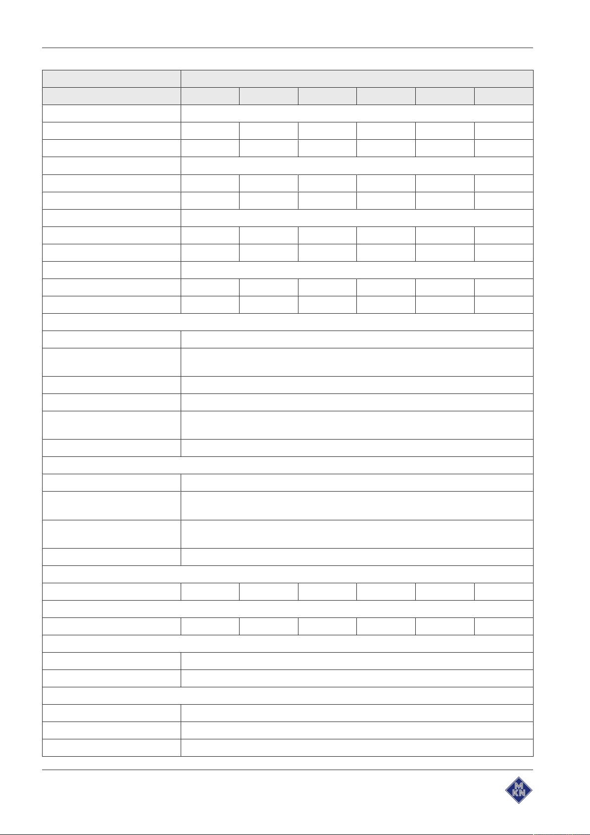
Description of the unit
Model: FKECOD
Size 615 621 115 121 215 221
Voltage (V) 400
Connected load (kW) 10.4 20.9 15.9 30.5 31.7 60.9
Fuse (A) 3 x 16 3 x 35 3 x 25 3 x 50 3 x 50 3 x 100
Voltage (V) 415
Connected load (kW) 11.2 22.5 17.1 32.8 34.1 65.5
Fuse (A) 3 x 16 3 x 35 3 x 25 3 x 50 3 x 50 3 x 100
Voltage (V) 440
Connected load (kW) 10.4 20.9 15.8 30.5 31.5 60.9
Fuse (A) 3 x 16 3 x 35 3 x 25 3 x 50 3 x 50 3 x 100
Voltage (V) 480
Connected load (kW) 12.3 20.9 18.9 32.6 37.6 65.1
Fuse (A) 3 x 16 3 x 35 3 x 25 3 x 50 3 x 50 3 x 100
Soft water connection
Type of water Soft water, cold
Carbonate hardness
CaCO3(mmol/l (°dH))
Chloride Cl (mg/l) < 50
Iron Fe (mg/l) < 0.1
Connection pressure (kPa
(bar))
Connection (") R 3/4
Tap water connection
Type of water Tap water, cold
Carbonate hardness
CaCO3(mmol/l (°dH))
Connection pressure (kPa
(bar))
Connection (") R 3/4
Water consumption for steaming
Soft water (l/h) 16 21 18 24 36 48
Water consumption for Combisteaming
Soft water (l/h) 3,5 4,6 4 5,3 8 10,6
< 0,9 (5)
200 (2) — 600 (6)
< 4 (22)
200 (2) — 600 (6)
Water consumption for WaveClean cleaning program
Soft water (l) 3
Tap water (l) 32
Wastewater connection
Wastewater type Dirty water, maximum 80 °C
Connection to unit (mm) 50
Maximum length (m) 1
14 Installation instructions
10013865-0AIBE-B
Page 15
Description of the unit
Model: FKECOD
Size 615 621 115 121 215 221
Temperature resistance (°C) 95
Maximum flow rate (l/min) 10
Exhaust air connection
Connection to unit (mm) 53 73
Maximum length (m) 2,5
Temperature resistance (°C) 180
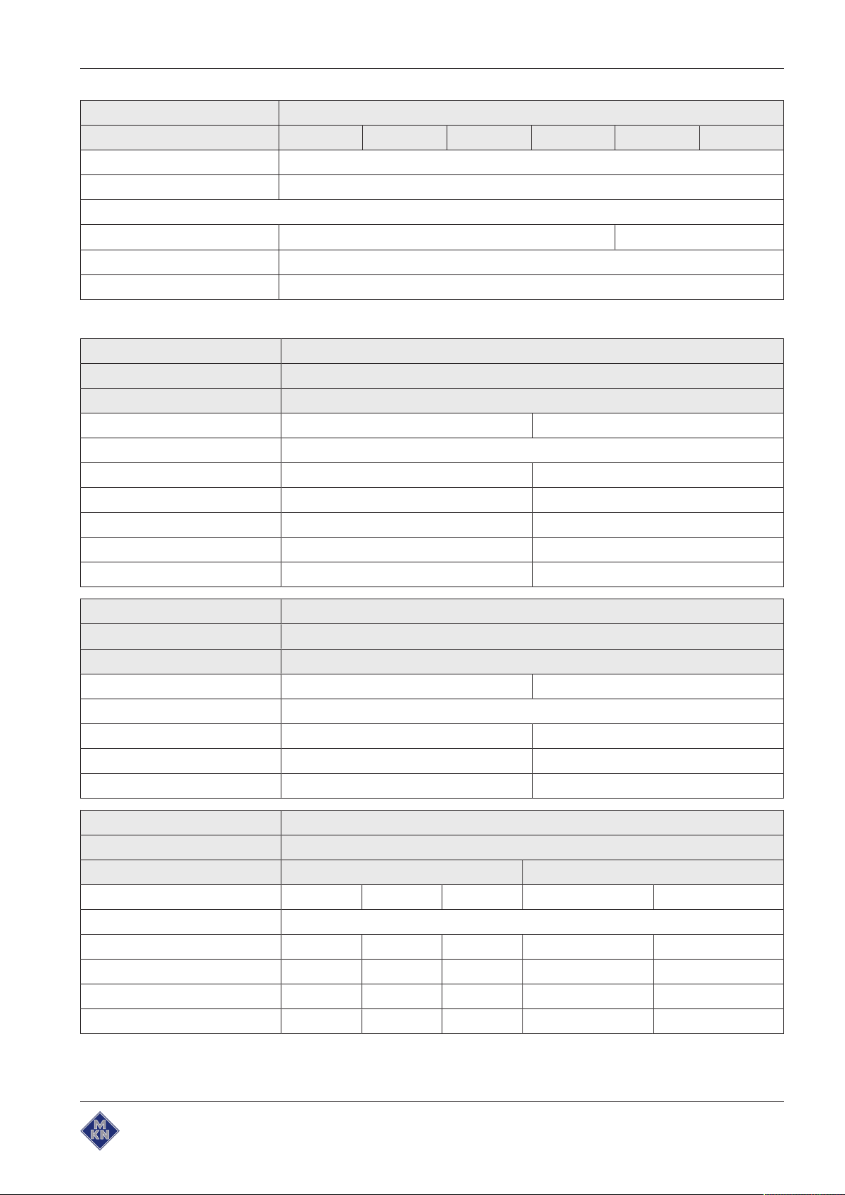
Transformer voltage
Type of connection 3NPE / AC 50/60Hz
Voltage range (V) 200 — 240
Transformer T1
Marking or colour of the cores Blue Red
Voltage measured (V) Voltage at the transformer (V)
190 — 200 0 200
201 — 220 0 220
221 — 230 0 230
231 — 240 0 240
241 — 250 0 250
Type of connection 3NPE / AC 50/60Hz
Voltage range (V) 380 — 415
Transformer T1
Marking or colour of the cores Blue Red
Voltage measured (V) Voltage at the transformer (V)
370 — 380 0 220
381 — 400 0 230
401 — 420 0 240
Type of connection 3PE / AC 50/60Hz
Voltage range (V) 380 — 480
Transformer T0 T1
Marking or colour of the cores T0 - 0V T0 - 230V T0 - 400V Blue Red
Voltage measured (V) Voltage at the transformer (V)
370 — 380 0 219 400 0 230
381 — 415 0 230 400 0 230
416 — 450 0 230 440 0 230
451 — 490 0 230 480 0 230
10013865-0AIBE-B
15Installation instructions
Page 16
Description of the unit
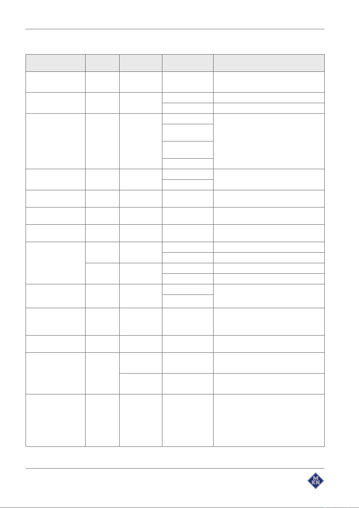
Basic control setting
Basic setting ParametersStandard
value
Date / time yyyy - mm - dd
Unit of temperature 1 °C °C Celsius (°C)
Altitude 2 0—999 0—999 m Request the altitude above sea level from
80% power 3 100 80% Power can be limited to 80% (for special
Actual voltage 14 400 100 — 500V Set the local, mean voltage between the
Audible signal
volume
Signal tones Sound 1 Sound 1 — 4 There are 4 sets of different sounds
33 Medium Individual Sets the volume.
Adjustment
range
hh : mm
°F Fahrenheit (°F)
1000 m—1999
m
2000 m—2499
m
2500 m or higher
100%
Explanation
Year - Month - Day
Hour : Minute
the local weather station. If the altitude is
unknown, set 0 – 999 m.
applications).
line conductors.
available.
Unit of volume 34 ml (ml) Millilitre (ml)
(fl.oz.) Fluid ounce (fl.oz.)
35 Imperial
(fl.oz.)
Power optimisation
system
Water filter
maintenance
Network DHCP Network address
Kitchen management
system
Settings parameters 1. Set parameters via the roller.
42 Off On If a power optimisation system is
44 0 0 — 99900 l Water quantity up to the maintenance
Disabled Active
Ethernet Ethernet
Imperial (fl.oz.) Imperial fluid ounce
U.S. (fl.oz.) U.S. fluid ounce
Off
and DHCP
Disabled
Serial
connected, "On" must be selected for the
unit to heat.
message.
0 = No maintenance message
Select and set interface.
Port and unit address can be set.
Type of signal transmission
2. Tap the "Read" button to display the
set value.
3. Specify another value via the button
panel.
4. Press the "Write" button to save the
new value.
16 Installation instructions
10013865-0AIBE-B
Page 17

Basic control setting (Advanced)
Description of the unit
Basic setting ParametersStandard
value
Ready2Cook
preheating
temperature
Time extension for
condensation hood
Preselect steaming
temperature
Preselect
Combisteaming
temperature
Preselect hot air
temperature
Preselect
regeneration
temperature
Maximum waiting
time after
Ready2Cook, for T <
250 °C
4 15 0 — 30% If the unit is fully loaded with a large mass
5 60 0 – 600s Time extension for the condensation hood,
9 100 30 °C — 130 °C Preset temperature for steaming
10 150 30 °C — 250 °C Preset temperature for Combisteaming
11 180 30 °C — 250 °C Preset temperature for hot air
12 130 30 °C — 150 °C Preset temperature for regeneration
37 120 0 — 300min Maximum waiting time after the
Adjustment
range
Explanation
(roasts, loaves of bread), increase the
preheat temperature so that the cooking
zone temperature does not drop too
suddenly.
after the cooking zone door has been
opened
Ready2Cook temperature is reached, for
set value < 250 °C
Maximum waiting
time after
Ready2Cook, for T >
250 °C
Generator mode 45 0 0 = No
Cleaning monitoring 46 0 0 = No
Steam elimination 48 1 0 = Low
Time format 675 0 0 = 24h
38 30 0 — 60min Maximum waiting time after the
1 = Yes
1 = Yes
1 = Normal
2 = High
1 = 12h
Ready2Cook temperature is reached, for
set value > 250 °C
If a generator is used to supply electricity
When cleaning monitoring is activated, a
message appears if the cleaning program
has not been started for more than 1 day.
Sets the steam elimination level
Sets the 12h or 24h time format
10013865-0AIBE-B
17Installation instructions
Page 18

Transporting the unit
4 Transporting the unit
CAUTION
Risk of property damage and personnel injury from tipping
equipment
• Do not linger next to or behind raised equipment.
• Move raised equipment carefully.
ATTENTION
Risk of physical damage from improper transport
• Transport the unit upright.
• Do not tilt or stack the unit.
• Pay attention to protruding parts when transporting the
unpacked unit.
Prior to transporting the unit to the installation site, ensure that:
• The roadway has adequate load-bearing capacity.
• Wall openings are large enough.
4.1 Transporting the unit to the installation site
Image: Lengthwise and crosswise transport on pallet
Use suitable transport means to move unit to installation site.
18 Installation instructions
10013865-0AIBE-B
Page 19

4.2 Unpacking the unit
Transporting the unit
CAUTION
Risk of injury from sharp edges
• Wear protective gloves.
When unpacking the unit, inspect it for transport damage.
Do not install damaged units or put into service.
1. Remove the packaging.
2. Pull the protective film off the unit.
3. Remove the packaging material from the cooking zone
completely.
4. Clean the unit (see "Cleaning and maintaining the unit" in the
operating instructions).
5. Enter the information from the nameplate into the commissioning
report.
10013865-0AIBE-B
19Installation instructions
Page 20

Setting up the unit
5 Setting up the unit
WARNING
Risk of burns from spraying hot fat
• Set up deep fat fryers outside the range of the hand shower.
CAUTION
Risk of crushing from improper setup
• Protect the unit and work area during setup and alignment.
CAUTION
Risk of fire from failure to observe applicable regional fire
prevention regulations
• Observe applicable regional fire prevention regulations.
ATTENTION
Risk of physical damage from overheating of the unit
• Do not set up the unit close to heat sources.
20 Installation instructions
10013865-0AIBE-B
Page 21

5.1 Maintaining minimum clearances
A
C
B
D
Image: Minimum clearances to walls, ceiling or units
Setting up the unit
A B C D *
50 100 500 50
All dimensions in mm
* Recommended for service work 500 mm
The following clearances from walls, ceilings or other equipment must
be maintained when setting up the unit:
• Left, right and rear at least 50 mm.
• For service work, 500 mm on the left is recommended.
• For parking the tray trolley, 800 mm on the left.
• Clearance from heat sources (baking oven), 500 mm on the left.
• Clearance to deep-fat fryers, at least one length of the hand
shower on the left and right.
• There must be no water, gas or electric lines in the ceiling above
the unit.
10013865-0AIBE-B
21Installation instructions
Page 22

Setting up the unit
5.2 Lifting the unit off the pallet
CAUTION
Risk of property damage and personnel injury from tipping
equipment
• Do not linger next to or behind raised equipment.
• Move raised equipment carefully.
ATTENTION
Risk of physical damage from lifting the unit incorrectly
• Place the forks of the lift truck next to the waste trap.
Requirement Unit unpacked
Protective film removed
Unit cleaned
Image: Lifting the unit off the pallet
1. Slide the forks of the pallet truck under the unit and to the right of
the waste trap.
2. Lift the unit off the pallet.
5.3 Setting up the unit on the equipment legs
Requirement The floor must carry the weight of the unit
1. Lift the unit with the pallet truck.
2. Move the unit to the installation site.
3. Place the unit on the floor.
4. Set up the unit in accordance with the planning drawing (see
"Planning drawing").
22 Installation instructions
10013865-0AIBE-B
Page 23

5.4 Setting up the unit on a base frame
ab
d
c
e
f
Image: Setting up the unit on a base frame
Setting up the unit
a Lifting fork d Stud bolt
b Waste trap on the unit e Equipment leg
c Base frame f Unit
Requirement The base frame must carry the weight of the unit
Base frame levelled
Base frame must be set up in accordance with the planning drawing
1. Lift the unit.
2. Place the unit over the stud bolts and onto the base frame.
CAUTION
Risk of scalding due to spillage of hot cooked food
• Attach sticker if the upper slide-in rails are higher than 1.60
m.
Image: Attach a warning sign about the shelf height
3. Clean the adhesive surface for the sticker.
10013865-0AIBE-B
4. Attach the sticker to the cooking zone door at a height of 1,6 m.
23Installation instructions
Page 24

Setting up the unit
c
b
d
A
B
c
a
5.4.1 Installing the support rack
Depending on the version, the base frame can be equipped with a
support rack.
The support rack is used to hold containers, metal trays and grates.
Image: A Stop profile, B Support rack
Requirement Pins installed in the uprights of the base frame
a Stop profile c Outboard support rack
b Pin d Inboard support rack
1. Place the stop profiles on the pins (at the back).
2. Install the support racks.
5.5 Aligning the unit
5.5.1 Aligning countertop unit
Requirement Base frame levelled
Level the unit by screwing the equipment legs in or out.
Fill out the Commissioning report.
5.5.2 Aligning floor-standing units
ATTENTION
Risk of water discharge from leaking cooking zone
The cooking zone will leak if the tray trolley is not aligned.
• Operate a floor-standing unit only with the tray trolley.
• Align the tray trolley carefully.
The tray trolley is needed to align a floor-standing unit.
Prepare the tray trolley.
Aligning tray trolley
Requirement The floor under and in front of the unit is flat
1. Level the unit by screwing the equipment legs in or out.
2. If the floor conditions are poor, insert spacers on the casters of the
tray trolley.
24 Installation instructions
10013865-0AIBE-B
Page 25

Setting up the unit
a
c
b
d
e
f
3. Open the cooking zone door.
4. Move the tray trolley into the unit until it stops and check the
alignment.
5. Close the cooking zone door.
The sheet metal seal on the tray trolley should make full
contact (no gaps) with the door seal.
The shelves in the unit should be horizontal.
6. Fill out the Commissioning report.
Aligning tray trolley with insertion system
The Combisteamer can be equipped with the
system(optional).
Image: Aligning the tray trolley with the insertion system
a Tray trolley d Equipment leg
b Distance e Support roller
c Guide rail f Push handle
EasyIn
insertion
10013865-0AIBE-B
1. Level the unit by screwing the equipment legs in or out.
2. Open the cooking zone door.
3. Place the tray trolley against the guide rails.
4. Screw the equipment legs in or out, until the support rollers are 1
mm — 5 mm above the guide rails.
5. Retract the tray trolley.
6. Level the guide rails.
7. Move the tray trolley into the unit until it stops and check the
alignment.
The casters of the inserted tray trolley should no longer have
floor contact.
8. Remove the push handle.
9. Close the cooking zone door.
10.Fill out the Commissioning report.
25Installation instructions
Page 26

Connecting the unit
A B
6 Connecting the unit
DANGER
Risk of personal injury and physical damage from electric
shock
• Prior to working on the unit, ensure that the unit has been
• Do not operate the unit with the housing open.
CAUTION
Risk of injury from sharp edges
• Wear protective gloves.
ATTENTION
Risk of physical damage from damage to the lines
• Remove and attach housing components carefully.
disconnected from the mains.
6.1 Opening and closing the housing
6.1.1 Removing and attaching side wall
Removing the side wall
Image: A Size 6XX and 1XX; B Size 2XX
1. Unscrew the screws on the side wall.
2. Pull the bottom edge of the side wall forwards.
3. Remove the side wall.
26 Installation instructions
10013865-0AIBE-B
Page 27

Attaching side wall
ATTENTION
Risk of physical damage from leaky housing
• Check seals when attaching the housing parts.
• Replace damaged gaskets.
1. Insert the top edge of the side wall.
2. Carefully push the bottom of the side wall inwards.
3. Fasten the side wall with the screws.
4. Check that the side wall is in contact with the unit on all sides.
6.2 Making the power connection
The unit must be connected on the basis of the information on the
nameplate and this manual.
ATTENTION
Risk of physical damage from incorrect connection voltage
Connecting the unit
• Before making the connection, measure the connection
voltage and check the set voltage on the transformers in the
unit.
Wiring diagram
The wiring diagram is included with the unit.
The wiring diagram and additional documents are available on the
manufacturer's Internet page by entering the serial number of the unit
(see Impressum).
Installation work
Electrical installation work must be carried out by an electrician.
Comply with the local regulations of the electrical utility company.
Power connection cable
Minimum requirements for the unit's power connection cable to the
electric mains:
Connection Power connection cable
Permanent connection for fixed
installation with a cable from the unit to
a separate connection box.
Connection of the unit with a plug.
Rubber sheath cable, oil-resistant,
shrouded and flexible in accordance
with IEC 60245-57 (for example
H05RN-F).
10013865-0AIBE-B
Permanent connection for fixed
installation with a permanently laid
cable and direct connection to the unit.
PVC sheathed cable for permanent
ducting in buildings or damp and wet
rooms.
27Installation instructions
Page 28
Connecting the unit
Permanent connection
CAUTION
Risk of property damage and personal injury from improper
installation
• In the case of a permanent electrical connection, install an
all-phase disconnect switch before the unit.
Install an all-phase disconnect switch if the unit will be connected
permanently to the electric mains.
Plug-in connection
CAUTION
Risk of property damage and personal injury from improper
installation
• The plug-in connection must be readily accessible.
If the unit is connected with a plug to the power-supply mains, use
plugs and sockets according to IEC60309.
The socket must be readily accessible so that the unit can be
disconnected from the electric mains at any time.
Insulation monitoring
If there is an unearthed network (IT network), the unit can be
incorporated into the insulation monitoring.
Fault current device
Image: RCD switch type A, circuit symbol
The unit can be connected to a fault current device.
If a fault current device is used, a fault current device type A (RCD
type A) must be installed, to ensure that AC fault currents and
pulsating DC currents are detected.
28 Installation instructions
10013865-0AIBE-B
Page 29

Equipotential bonding
Image: Equipotential bonding symbol
The unit must be included in a potential equalisation system by
means of appropriately sized wiring.
6.2.1 Matching the unit to the connection voltage
DANGER
Risk of personal injury and physical damage from electric
shock
Connecting the unit
• Prior to working on the unit, ensure that the unit has been
disconnected from the mains.
• Do not operate the unit with the housing open.
ATTENTION
Risk of physical damage from incorrect connection voltage
• Before making the connection, measure the connection
voltage and check the set voltage on the transformers in the
unit.
When the unit is delivered, it is preset to a certain connection voltage
or voltage range.
If the connection voltage on site differs from the preset connection
voltage, damage to the unit can arise.
Before connecting the unit, the connection voltage must be measured
and the transformers in the unit checked, and if necessary they must
be reconnected.
10013865-0AIBE-B
29Installation instructions
Page 30

Connecting the unit
A B
Nnc110 V
120 V
200 V
208 V
220 V
230 V
240 V
250 V
X1
X2
T1
480 V
440 V
400 V
242 V
230 V
219 V
0 V
A B
T0
Image: A Transformer position T1; B Connection for transformer controls
Requirement Unit not live
Image: A Transformer position T0, only for unit without neutral wire; B Transformer
connection
Left side wall removed
1. Measure the connection voltage with a suitable measuring device.
The voltage range must match that on the nameplate.
If there are voltage fluctuations, the maximum expected
voltage must be taken into account.
2. Check whether the transformer voltage is within the specified
range (see "Equipment and connection data").
If the set voltage differs, match the transformer voltage by
reconnecting.
Document the new voltage set on the sticker.
3. In the case of units with several transformers, repeat the
procedure for each transformer.
4. Close the housing (see "Opening and closing the housing").
5. Fill out the Commissioning report.
10013865-0AIBE-B
30 Installation instructions
Page 31

6.2.2 Connecting the power connection cable
a
b
c
d
DANGER
Risk of personal injury and physical damage from electric
shock
• Prior to working on the unit, ensure that the unit has been
disconnected from the mains.
• Do not operate the unit with the housing open.
DANGER
Risk of personal injury and physical damage from electric
shock
• Before connecting, ensure that the power connection cable
has been disconnected from the power supply.
• Ensure that the power connection cable is undamaged.
Connecting the unit
Image: Connecting the electric power cable
a Connection terminals c Electric power cable
10013865-0AIBE-B
b Cable tie d Cable gland
31Installation instructions
Page 32

Connecting the unit
Requirement Unit not live
Power connection cable not live
Unit matched to the connection voltage
Side wall open
1. Route the power connection cable into the unit through the cable
gland.
2. Connect the power connection cable in accordance with the wiring
diagram.
3. Secure the power connection cable with cable ties.
4. Tighten the cable gland securely to provide strain relief.
5. Close the housing (see "Opening and closing the housing").
6. Fill out the Commissioning report.
6.2.3 Connecting the power optimisation system
DANGER
Risk of personal injury and physical damage from electric
shock
• Prior to working on the unit, ensure that the unit has been
disconnected from the mains.
• Do not operate the unit with the housing open.
DANGER
Risk of personal injury and physical damage from electric
shock
• Before connecting, ensure that the power connection cable
has been disconnected from the power supply.
• Ensure that the power connection cable is undamaged.
The unit can be connected to a power optimisation system.
Requirement Unit not live
Power connection cable not live
Housing opened
1. Pull the power connection cable into the unit through the cable
gland.
2. Bring the power connection cable to the connection terminals.
3. Connect the power connection cable in accordance with the wiring
diagram.
4. Secure the power connection cable with cable ties.
5. Register the power optimisation system in the basic control
settings (see "Making the basic control settings").
6. Fill out the Commissioning report.
32 Installation instructions
10013865-0AIBE-B
Page 33

6.2.4 Connecting to the potential equalisation circuit
Image: Connecting the potential equalisation circuit
1. Run and attach potential equalisation line to the identified
terminal.
2. Fill out the commissioning report.
Connecting the unit
6.3 Connecting the kitchen management system
The units can be connected with a RJ45 plug to a kitchen
management system.
DANGER
Risk of personal injury and physical damage from electric
shock
• Prior to working on the unit, ensure that the unit has been
disconnected from the mains.
• Do not operate the unit with the housing open.
10013865-0AIBE-B
33Installation instructions
Page 34

Connecting the unit
a
b
c
d
e
Minimum requirements for the network cable
Type of network Ethernet
Cable quality 4-pair, shrouded patch cable
Cat-6 S/FTP
Connection to unit Shrouded RJ45 plug
Image: Connecting the kitchen management system
a RJ45 socket d Cable tie
b RJ45 plug e Ferrite ring
c Network cable
Requirement Unit not live
Housing opened
1. Pull the network cable into the unit through the cable gland.
2. Lead the network cable through the two ferrite rings, with one
winding through each.
3. Connect the network cable to the unit with the RJ45 plug.
4. Register the network in the basic control setting (see "Making the
basic control setting").
5. Fill out the Commissioning report.
10013865-0AIBE-B
34 Installation instructions
Page 35

6.4 Making the basic control setting
a b
cd
e
Image: Main menu
Connecting the unit
a Main menu d "Equipment functions" button
b
FlexiHelp
c Language selection
6.4.1 Changing the basic control setting
By entering the password "2100", the basic settings for the installation
can be displayed and changed.
The basic settings are made in the dialogue.
Advanced settings are made via the parameters for the settings.
Requirement The unit is switched on
The Main menu is displayed
1. Tap the "Equipment functions" button.
The
Equipment functions
2. Tap the "Equipment settings" field.
The
PIN
3. Enter the password.
4. Tap the
Confirm
button e
menu is displayed.
window opens.
button.
Back
button
10013865-0AIBE-B
The
Equipment settings
The basic settings can be changed (see "Equipment and
connection data").
5. Fill out the Commissioning report.
menu is displayed.
35Installation instructions
Page 36
Connecting the unit
6.5 Making the water connection
Installation work involving drinking water must be performed by an
authorised plumbing contractor.
Observe applicable regional regulations with regard to drinking water
installations and connection data (see "Equipment and connection
data").
The unit has a connection for permanent attachment the drinking
water system.
The unit is equipped with a permanent connection for:
• Softened drinking water for steam generation
• Drinking water for cooling, rinsing and cleaning
CAUTION
Hygiene risk from contaminated drinking water
• The connection to the drinking water supply must be
equipped with a backflow preventer.
ATTENTION
Risk of physical damage from the wrong water quality
• Ensure that the water quality complies with the equipment
and connection data.
Always connect both water connections to the unit.
36 Installation instructions
10013865-0AIBE-B
Page 37

6.5.1 Connecting the tap water connection line
a
b
e
c
d
f
Image: Water connection
a Soft water d Tap water connection
b Backflow preventer e Tap water connection line
c Soft water connection f Tap water
Connecting the unit
Requirement Water pressure complies with the specified range (see "Equipment
and connection data")
Backflow preventer installed
The connection lines are pressure-tight and suitable for tap water
1. Connect the connection lines to the tap water valves using seals.
2. Flush the connection lines thoroughly.
3. Insert dirt filters into the water connections on the unit.
4. Connect the tap water connection line to the unit.
5. Connect the soft water connection line to the unit.
6. Open the tap water valves and check the threaded connectors for
leaks.
7. Fill out the Commissioning report.
10013865-0AIBE-B
37Installation instructions
Page 38

Connecting the unit
a
b
c
d e
f
g
h
6.5.2 Connecting softened tap water to both connections
If only softened tap water is available at the installation site, use a Tpiece to connect both water connections on the unit to each other.
Image: Connecting softened tap water to both connections
a Softened tap water e Tap water connection
b Backflow preventer f Dirt filter
c Connection line g T-piece
d Softened tap water connection h Seal
Requirement Water pressure complies with the specified range (see "Equipment
and connection data")
Backflow preventer installed
The connection line is pressure-tight and suitable for tap water
1. Connect the connection line to the tap water valve for soft water
using a seal.
2. Flush the connection line thoroughly.
3. Insert dirt filters into the water connections on the unit.
4. Connect the T-piece to the unit.
5. Connect the connection line for soft water to the T-piece using a
seal.
6. Open the tap water valve and check the threaded connectors for
leaks.
7. Fill out the Commissioning report.
38 Installation instructions
10013865-0AIBE-B
Page 39

6.6 Making the wastewater connection
a
b
c
d
e
c
b
a
f
Installation work involving wastewater must be performed by an
authorised plumbing contractor.
Observe the applicable regional regulations of the sewage utility
involved.
6.6.1 Connecting the wastewater line to a permanent connection
Connecting the unit
Image: Wastewater line to a permanent connection
a Wastewater connection d Sewer system waste trap
b Wastewater line e Pipe clamp
c Sewer system f Vacuum breaker
If a waste trap is installed in the wastewater system, a vacuum
breaker must be installed in the wastewater line.
Requirement Wastewater line complies with the specifications (see "Equipment
and connection data")
1. Install the wastewater line up to the connection at the sewer
system.
2. Secure the wastewater line with pipe clamps.
3. Fill the waste trap on the unit with tap water.
4. Fill out the Commissioning report.
10013865-0AIBE-B
39Installation instructions
Page 40

Connecting the unit
6.7 Making the exhaust air connection
When setting up the unit under a ventilation system, observe the
regional regulations for heating, ventilation and air conditioning
systems.
ATTENTION
Risk of physical damage from fouling of the exhaust air
ducts
• Do not connect the exhaust air line directly to the ventilation
system.
ATTENTION
Risk of corrosion damage from condensate
• Install the exhaust air line such that condensate cannot
collect.
6.7.1 Connecting the exhaust air line
Image: Connecting the exhaust air line
Requirement Exhaust air line complies with the specifications (see "Equipment and
connection data")
1. Connect the exhaust air line to the steam outlet.
2. Route the exhaust air line with a 3° rise as far as the ventilation
system.
3. Fasten the end of the exhaust air line 50 mm — 200 mm
underneath the ventilation system.
4. Fill out the Commissioning report.
40 Installation instructions
10013865-0AIBE-B
Page 41

7 Testing the function
DANGER
Risk of personal injury and physical damage from
unsuccessful operational check
• Do not put the unit into service.
• Contact customer service.
Requirement Power connection made
Water connection made
Wastewater connection made
Unit cleaned
7.1 Checking the controls
1. Switch on the unit and start any cooking program (see Operating
instructions).
Testing the function
Set the cooking zone temperature to a higher temperature than
the current cooking zone temperature.
The unit heats up.
Once the set temperature is reached, heating switches off.
The temperature no longer increases.
The controls are functioning.
2. Switch off the unit.
3. Fill out the Commissioning report.
10013865-0AIBE-B
41Installation instructions
Page 42

Testing the function
7.2 Checking the monitoring of the cooking zone door
1. Switch on the unit and start any cooking program (see operating
instructions).
The unit starts to heat.
The fan wheel is turning.
2. Open the cooking zone door during operation.
The unit shuts off the heating function.
The fan wheel comes to a stop.
The monitoring of the cooking zone door is functioning.
3. Close the cooking zone door.
4. Switch off the unit.
5. Fill out the commissioning report.
7.3 Running the self-diagnosis
1. Switch on the unit.
2. Start the "CombiDoctor" self-diagnosis program (see "Checking
the unit" in the Operating instructions).
If no errors are displayed, the unit is OK.
3. Switch off the unit.
4. Fill out the Commissioning report.
42 Installation instructions
10013865-0AIBE-B
Page 43

8 Putting the unit into service
If the unit is not put into service immediately after being
connected and the function check, all inspections must be
repeated.
Requirement Power connection made
Water connection established
Wastewater connection established
Exhaust connection made (if required by the customer)
Operation successfully checked
Housing closed
1. Instruct the operator.
2. Fill out the commissioning report.
8.1 Filling out the Commissioning report
Putting the unit into service
General Yes No
Information from the nameplate entered?
SN: _____________________________ Typ: _____________________________
E: ________________________________________________________________
Bez: ______________________________________________________________
Item-Nr.: _____________________________ (if listed)
Obvious damage to the unit?
What and where?:
______________________________________________________________________________
Unit levelled?
Electrical connection Yes No
Power connection made properly?
Equipotential bonding Power optimizing system
Floating contact …
Electrical connections made properly?
Residual-current protective device connected immediately before this unit?
Residual-current protective device connected before this and other units?
Connection voltage measured?
Connection voltage: _______________ (V)
Set transformer voltage
T0: 0 V | ______ V | ______ V; T1: blue 0 V | red ______ V; T2/T3: blue ______ V | red ______ V
Kitchen management system Yes No
Has the kitchen management system been connected properly?
10013865-0AIBE-B
43Installation instructions
Page 44
Putting the unit into service
Basic control setting Yes No
Unit of temperature set?
°C °F
Have date and time been set?
Has software version been identified?
Version: __________
Altitude set?
0—999 m 1000 m—1999 m
2000 m—2499 m 2500 m or higher
80% power set?
100 % 80 %
Current voltage set?
Voltage: ________ V
Audible signal volume set?
quiet loud
Has signal tone been selected?
Volume unit set?
ml fl.oz. (Imperial)
fl.oz. (U.S.)
Power optimisation system set?
On Off
Water filter maintenance set?
No maintenance message Maintenance message at: _______________ l
Has network configuration been set?
DHCP IP address: ____________________________
Subnet mask: ____________________________ Gateway: ____________________________
Has kitchen management system been set?
Active Disabled
Ethernet
TCP port: __________
Unit address: __________
Water connection Yes No
Serial
Unit address: __________
Connection pressure within indicated range?
Connection pressure: _______________ ( _______________ ) kPa (bar)
Water connection made properly?
Lines and connections leak-tight?
Water connections connected with T-piece?
Connected only to softened tap water Connected only to tap water
44 Installation instructions
10013865-0AIBE-B
Page 45
Wastewater connection Yes No
Wastewater connection made properly?
Waste trap in the building Aerator
Funnel drain Floor gutter
Connection dimension of wastewater line: ____________________ mm
Exhaust air connection Yes No
Setting up below ventilation system?
Connected to exhaust air duct?
Connection dimension of exhaust air line: ____________________ mm
Length of exhaust air line: ________________________ mm
Function check Yes No
Controls are functioning?
Monitoring of the cooking zone door is functioning?
Self-diagnostic program run without faults?
Putting the unit into service
Fault: _______________________________________________________________________
Final notes Yes No
Was the unit put into service?
Comments:
Operator trained?
Electrical installation was provided by:
Company Installer City, date Signature
The connection to a kitchen management system was made by:
Company Installer Place, date Signature
Water installation was provided by:
Company Installer City, date Signature
Wastewater installation was provided by:
Company Installer City, date Signature
Exhaust air connection was provided by:
Company Installer City, date Signature
10013865-0AIBE-B
45Installation instructions
Page 46

Putting the unit into service
The function check was performed by:
Company Installer City, date Signature
Operator training was provided by:
Company Installer City, date Signature
46 Installation instructions
10013865-0AIBE-B
Page 47

Page 48

www.mkn.eu
 Loading...