

PIPE INSPECTION CAMERA SYSTEM
Please read these instructions completely before operating this system.
Please charge the battery firstly before using it.
MODEL: MKI-FH4
MANUAL

Catalog
CATALOG
SAFETY AND NOTICE
1.PARTS LIST
1.1 ACCESSORIES
1.2 C
ONTROL BOX
2.QUICK START GUIDE
2.1 CHARGING THE BATTERY
2.2 S
2.3 M
2.4 C
TARTING UP
AIN FUNCTION
HECKING WATERPROOF RING & ASSEMBLING SKID
3.RECORDING AND MENU
3.1 INSERT THE SD CARD AND ASSEMBLE THE MICROPHONE AND USB
F
LASH DRIVE
........................................................................................
.................................................................
.................................................................................
.......................................................................................
.....................................................................................
...............................................................
.....................................................................
........................................................................................
..................................................................................
.....................
.......................................................
.............................................................................................
2
3
5
5
7
8
8
9
11
12
13
13
3.2 R
3.3 R
3.4 P
3.5 P
3.6 M
3.7 D
3.8 Z
ECORDING VIDEO
ECORDING PHOTO
LAYBACK VIDEO
LAYBACK PHOTO
...................................................................................................
ENU
ELETE FILES
OOM IN & ZOOM OUT THE IMAGE (8 LEVELS)
.....................................................................................
4.METER COUNTER
5.KEYBOARD
5.1 KEYBOARD ASSEMBLE
5.2 K
EYBOARD
...............................................................................
...........................................................................................
.............................................................................
............................................................................
................................................................................
..............................................................................
...................................................................
........................................................................
6.TROUBLESHOOTING GUIDE
.................................
...............................................
14
15
15
16
17
19
20
21
22
22
23
24
2
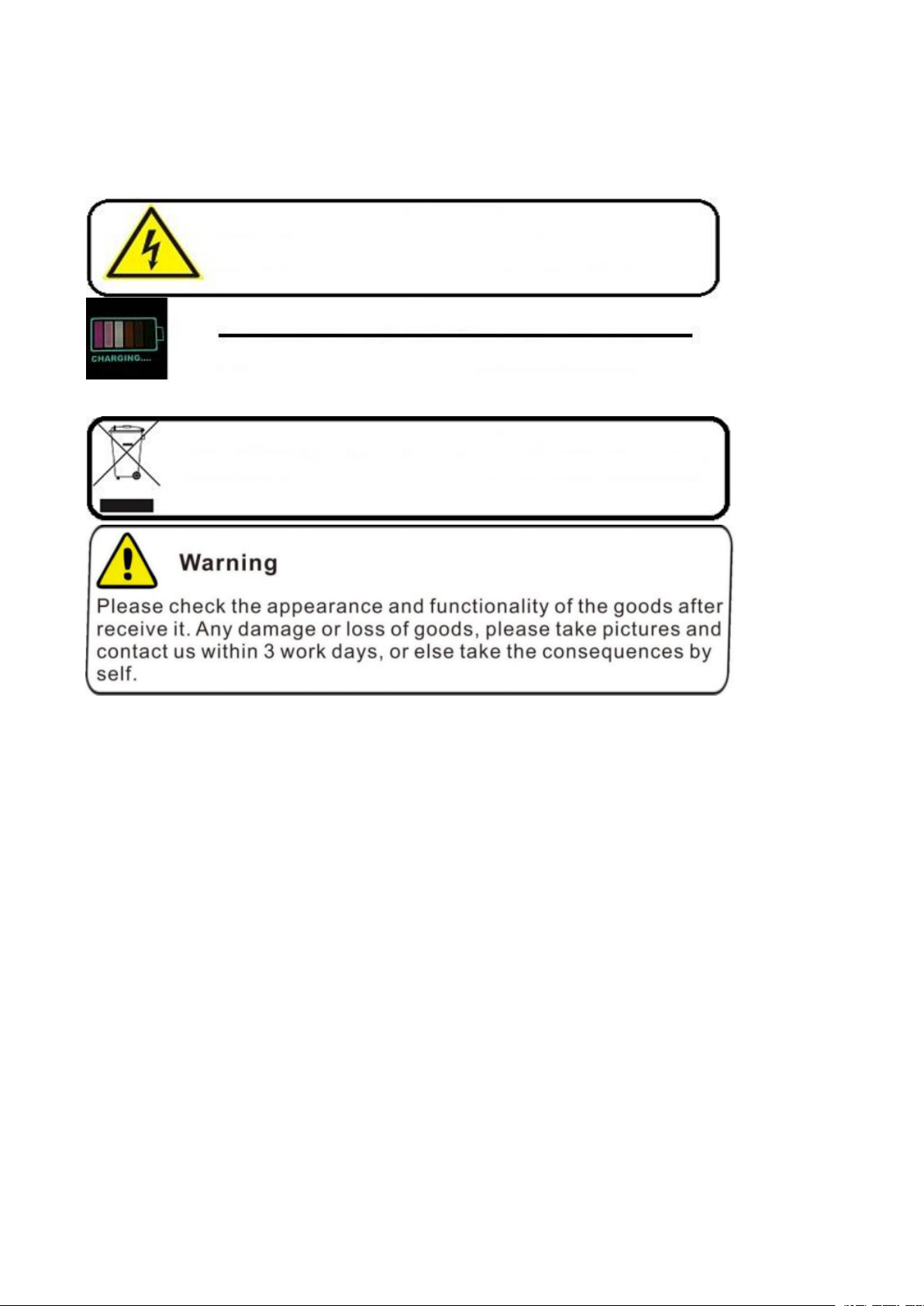
Warning
Warning
To Avoid electrical shock put the item indoor when Charging
Warning
Use only input 110~240V AC output DC 13.5V, 5000mA charger.
This machine can only use the original charger and lithium battery, reminding
the charging time is 5 hours. Please charge the battery before use!
Warning
Item contains battery, dispose according local legal requirements properly
After using the PT camera, clean the camera with water
Read this manual carefully before operating this system.
Avoid using the device in extreme humidity or temperatures as this may cause damage to the
device.
Do not drop or press on the system as this may cause damage to the device.
The warranty becomes void if any physical damage is present or if the system is disassembled by
the user.
Do not disconnect the SD card while recording or playing as this may damage the system and/or
the SD card.
Remember to always back up the data on your SD card.
Safety and Notice
For your safety
1. Do not attempt to insert, use, or charge a battery not designed for this inspection system.
2. Use the power supply only on even surfaces, without any cover. Open air and circulation around
the product must be available. The maximum ambient temperature is 50℃.
3. Risk of explosion may occur if an incorrect battery type is inserted or used. Dispose of used
batteries according to their instructions.
3

4. Keep the inspection system and its accessories out of the reach of babies, toddlers, and children.
In particular, small parts such as memory cards and battery could be easily dismantled and
swallowed.
5. Use only the original accessories to avoid possible risks to health and property, and thus meet all
related legal regulations.
6. When using the LED lights, do not use to close to human or animal eyes (particularly for babies,
toddlers, and children) to avoid injury.
7. In very rare occasions, Li-ion Batteries such as the one provided with this inspection system
could explode if a conductive material such as jewelry, keys or beaded chains touch exposed
terminals. The material may complete an electrical circuit and become quite hot. Exercise care in
handling any batteries, particularly when placing it inside your pocket, purse, or other container with
metal objects. In such an event, this could result in property damage, injury or burns. Do not
dispose of batteries in fire as they may explode.
Warranty
1. Warranty is void if damage or system failure occurred due to outside factors such as collision, fire,
flood, dirt, sewage, earthquake, and other force majeure events as well as incorrect usage of
electricity or use of non-original accessories.
2. It is the sole responsibility of the user if problems (such as data loss and system failure) occurred
due to non-factory installed software, parts, and/or non-original accessories.
Taking care of your inspection system
1. Always keep the inspection system in the pouch provided or other suitable cases for increased
protection against splashes, dust, and collision.
2. The only way of replacing the battery and the memory card is to open the Battery / Memory
cover. Use care when opening this cover to avoid damage the inspection system.
3. Dispose of unwanted batteries and inspection systems as permitted by the laws in your country.
4. Water may cause a fire or electric shock. Therefore, store your battery in a dry place.
5. If your control component becomes wet, wipe it with a dry cloth as soon as possible.
6. Do not drop, knock, or shake the inspection system. Inappropriate behavior when using the
camera system may damage the internal electronic circuit board or deform the lens shape.
7. Do not use harsh chemicals, cleaning solvents, or strong detergents to clean the inspection
system.
8. To avoid unclear images, be sure to clean the inspection system lens before taking pictures or
recording videos. Use a lens brush or soft cloth to clean the lens.
9. To avoid the loss of video and photos on the memory card, you should make a backup copy to a
computer or optical disc as soon as possible. Memory cards should not be considered as a long
term storage device.
10. Before initial use of a memory card, it is recommended to use the inspection system to format
the card first.
11. Remember to slide the write-protect tab (if available) to the unlock position. Otherwise, all data
(if any) on the memory card is protected and the card cannot be edited or formatted.
Operating environment
1. The camera system operating temperature is between -10ºC ~ 50℃(14℉~ 122℉). It is normal
for the operating time to be shortened when the temperature is low.
2. The capacity of your inspection system battery will reduce each time it is charged/emptied.
3. Storage at too high or low temperatures will also result in a gradual capacity loss. As a result, the
operating time of your inspection system may be considerably reduced.
4. It is normal for the camera system to become warm during operation, because the inspection
system casing can conduct heat.
4
1.Parts List
Item
Image
Description
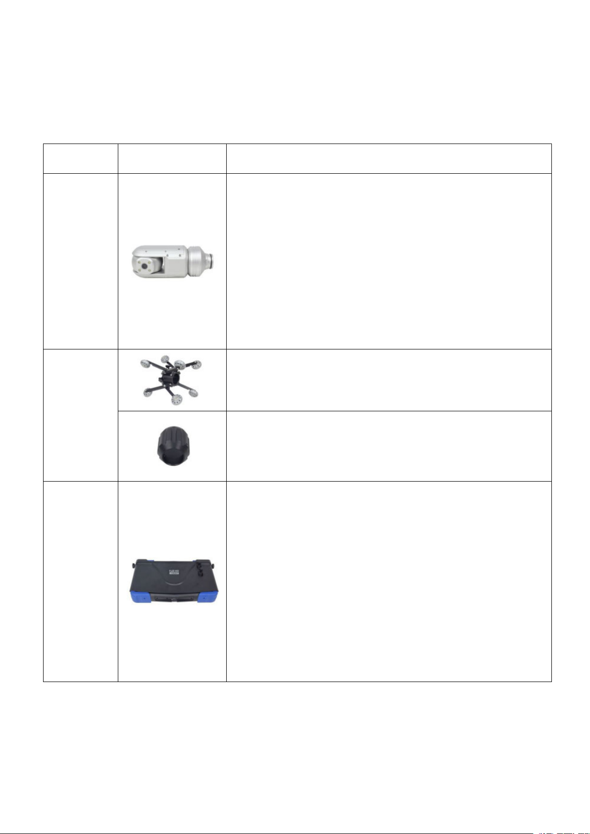
Camera
Head &
Size: 60*146mm
Total Length: 360mm
Pixel: 1920*1080
View Angle: 105°
Rotation: horizontal 360° vertical 180°
Sensor Size: 1/2.9” SONY CMOS
Manual focus
Focus Distance: 200~1200mm
Camera Light: 4PCS highlight LEDS (white) adjustable
Adjustable lamp holder 8 levels
Total LED Power: 4W
Lens Material: sapphire glass
Shell Material: aluminum alloy
Waterproof Rating: IP68
Skids
Flexible Distance: 250~360mm
S60-80
Control
Case
Size: 401*240*86.5mm
10.1 inch LCD highlight LCD screen
Total Pixels: 1280*800
10.1 inch high brightness screen brightness parameters:
800nits
Storage Media: SD card (up to 256G)
USB function (up to 256G)
Main Functions: video, photo, audio, typing, counting
External speaker
8x digital zoom
Video Format: AVI Picture Format: JPEG
External HDMI (High Definition Interface)
Battery: Polymer lithium battery 6000mAh 12V
Metric and imperial conversion
Reset function
1.1 Accessories
5
Item
Image
Description
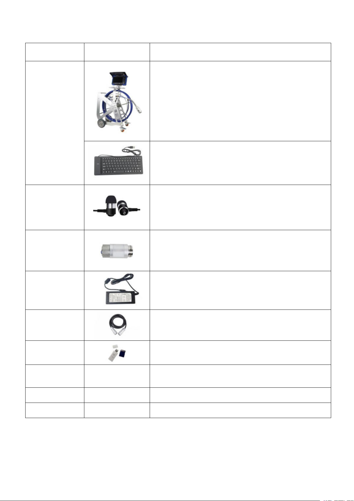
Cable Wheel
Cable Size: 875*978*406mm
Cable Material: fiberglass rod
Cable Length: 60m standard
Cable Diameter: ø9.5mm, 9cores
Cable Wheel Material: stainless steel and aluminum
alloy
Counter Accuracy: 0.1m
Counter Deviation: ±1%
Metric and imperial conversion
Reset function
Keyboard Size: 300.8*115.8*12.25mm
Language: English
Keyboard Interface: USB
Text Edit Line: PAL 24 letters 10 line
Edit Page: 4 pages
Microphone
Speaker Size: 10mm
Frequency Range: 18-20,000Hz
Sensitivity: 116dB
Cable Length: 1200mm
Plug Diameter: 3.5mm
Launcher
Transmitter: built-in 512Hz
Effective Distance: 5m
Connection
Wire
Input: AC100-240V~50/60Hz
Output: DC 13.5V/5A
DC Plug Diameter: 2.1mm
Cable
Connection
Size: ø5.3-7* 1500mm
GX12-7 waterproof self-locking connector
SD Card and
Card Reader
Screw Driver
Waterproof
Ring
Manual
6
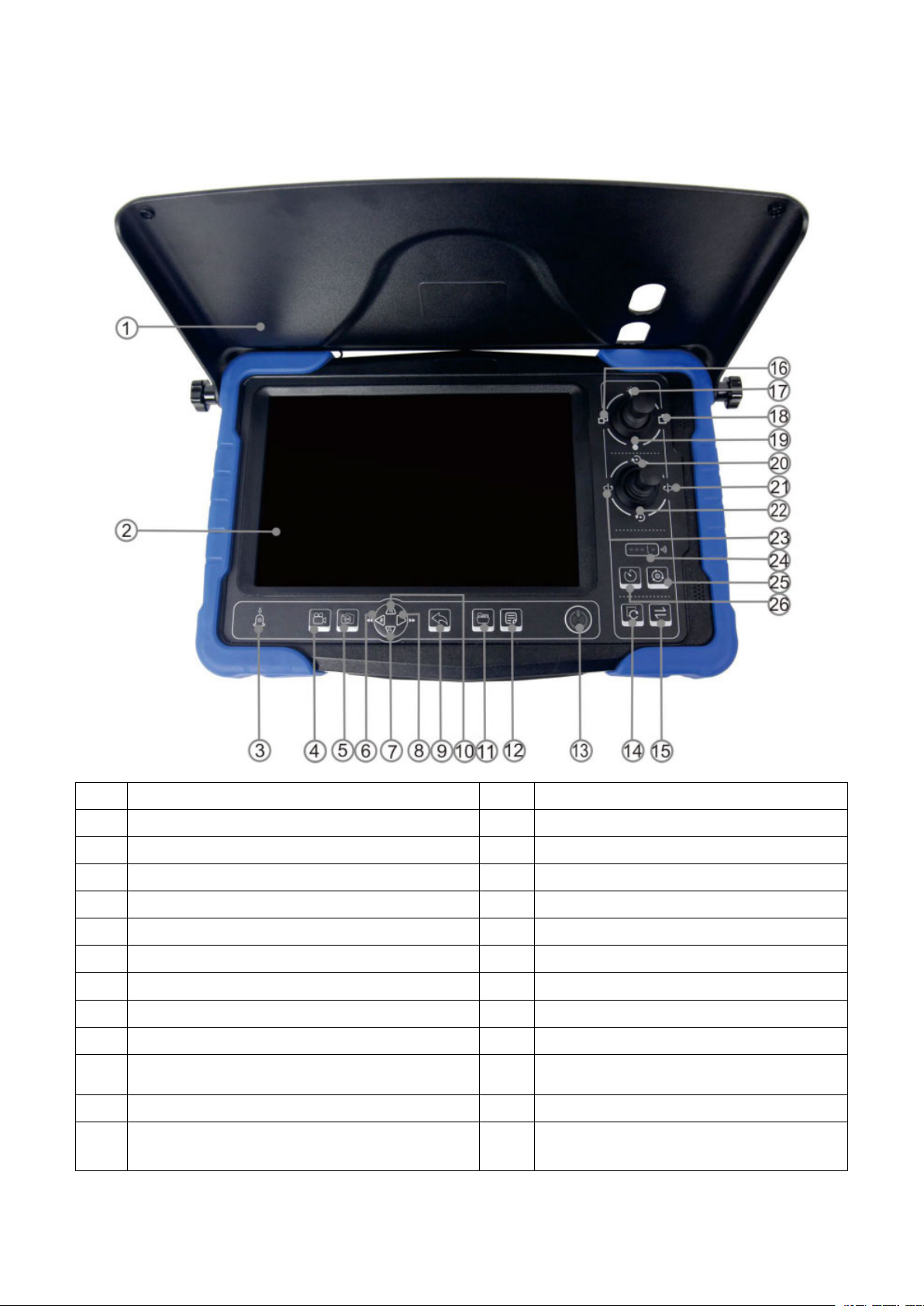
1.2 Control Box
1
Sunshade
14
Reset
2
10.1 inch screen
15
Metric / Imperial
3
Infrared receiving window
16
Far focus
4
Video / video pause or resume / delete
17
Light brightness up
5
Confirm / one-touch photo / play or pause
18
Near focus
6
Left button / rewind / recording switch
19
Light brightness down
7
Down button / volume -
20
Tilt-up
8
Right click / fast forward
21
Pan-right
9
return
22
Tilt-down
10
Up button / volume +
23
Pan-left
11
Record stop / one-click jump to folder list /
replay
24
Speed light / WIFI indicator
12
menu
25
Auto / menu
13
Long press for 3 seconds on / off power /
short press to open WIFI
26
Speed / step
7
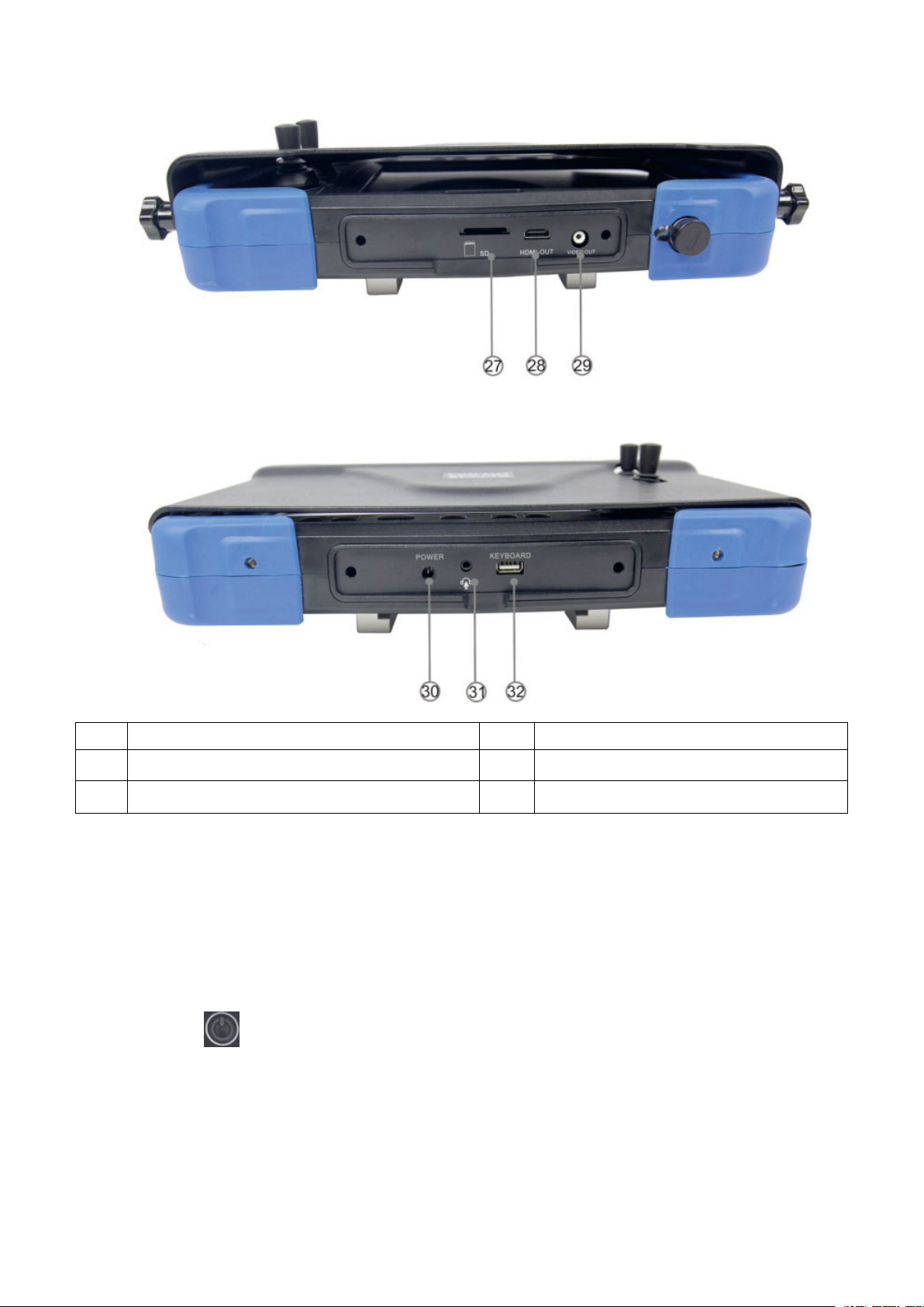
27
SD card slot
30
Charge jack
28
HDMI-OUT
31
Earphone / Mic.
29
Video output
32
USB keyboard port
2.Quick Start Guide
2.1 Charging the Battery
1. Connect the adapter to the AC cable
2. Plug in the 220V power supply
3. Connect the plug to the jack of control box
4. Blinks while “ ” button charging, stops flashing when fully charged
8

2.2 Starting Up
1. Take out the control terminal and insert it into the coil
2. Tighten the screws
3. Open the sunshade
4. Connect one end of the cable to the coil
5. Connect the other end to the control box
6. Insert the keyboard plug into the control terminal
7. Camera and connector alignment
8. The camera and connector are tightened
9. The other end is aligned with the coil connector
9

10. Tighten the other end to the coil connector
13. The fiber optic cable is placed in the cable clamp
14. Tighten the screw after adjusting the direction of the calibration handle
11. Unlocking coil
12. Fixed caster
15. Adjust the direction of the calibration handle on the other end
16. Tighten the screws
17. Press and hold “ ” button for 3 seconds to start
10

2.3 Main Function
2. Adjust the camera focal length left and right
1. Adjust the brightness of the lamp up and down
11

3. Press and hold to pan and tilt the camera
2.4 Checking Waterproof Ring & Assembling Skid
1. First remove the camera
2. Tighten the screws after loading the bracket
3. Tighten the camera and coil connector
1. First remove the camera
2. Tighten the screws after loading the bracket
3. Tighten the camera and coil connector
12

3.Recording and Menu
1. Insert the SD card into the slot and press it gently. Make sure the SD card is in good contact with
2. Warning: Pay attention to the direction of the SD card and plug it in reverse will damage the SD
3.1 Insert the SD Card and Assemble the Microphone and USB
Flash Drive
the finger, then gently press and pull the SD card
card
13

3.2 Recording Video
3. press the " " button again to resume recording
4. Record video can take pictures
1. Press the " " button to record the video
2. Press the " " button to pause
14

3.3 Recording Photo
Press the “ ” button to snap picture
3.4 Playback Video
1. Press the “ ” button
2. Press the “ ” button Video Files
3. Select the file you need
4. The monitor plays the video
5&6. Press the “ ” button adjust the volume
15

3.5 Playback Photo
Follow the same steps that the “Playback Video” has mentioned
16

3.6 Menu
Select the operating language
Set the date and time, press OK to confirm
Time format setting
800X600
1024X768
1280 X1024
1366X768
1440 X900
1280X720
1920X1080
Press “ ” key enter into main menu
Language
Date Time
Date Format
Display
17

Video Setting
Frame rate quality etc
AUTO
1080P-PAL
1080P-NTSC
720P-PAL
720P- NTSC
CVBS-PAL
CVBS-NTSC
1minutes
5 minutes
10 minutes
15 minutes
30 minutes
Very Good
Good
Normal
Bad
Low
Video System
Video Time
Length of the video recording
Quality
Perimeter (unit mm)
18

Disk Select
SD1
SD2
CANCEL: The system will not format the SD card
OK: The system will format the SD card (caution: PLS backup the data of the SD card before
Software Update
cancel: The system will not update the firmware
upgrade: The system will update the firmware
No: Leaves set up as it is
Yes: Factory resets the system
Format Disk
operating)
Upgrade
System Restart
3.7 Delete Files
Please make sure the files you really want to delete, the files won’t be found after deleting.
19

Press “ ” button to choose the file you want to delete, one and all
Press “ ” button to delete it
3.8 Zoom in & Zoom out the Image (8 levels)
1. Press the "up" navigation button to enlarge the image
2. Press the navigation button "down" to zoom out the image
20

4.Meter Counter
2. Press the “ ” button to reset the value of cable length
1. Press the “ ” button to alternate metric and imperial unit
21

3. Hold the “ ” button for 3 seconds, the meter count number hide; hold the button again for 3
seconds, the meter count number show
5.Keyboard
5.1 Keyboard Assemble
1. Insert the USB plug of keyboard to the “KEYBOARD USB” jack
2. Type the letters on the keyboard
3. The letters will show on the screen
22

5.2 Keyboard
Esc
Clear the cursor current settings
back to the first line and the first position
F1
the cursor from any page back to the first line and the first position
F2
Select text over internal video
F3
Select text over external video signal
F4
Shift display up
F5
Shift display down
The font and text size are fixed and cannot be changed.
The basic operation of the text overlay unit is straight forward. A flashing underscore cursor
indicates the current screen position. This cursor can be moved the screen by the keyboard cursor
keys. The cursor will wrap around the screen left and right, top and bottom. If no key is pressed then
the cursor will disappear after approximately ten seconds. The video text overlay unit uses the
standard US keyboard mapping.
Standard US keyboard mapping used by the video text overlay unit. By default all US units are
supplied with this.
The alphanumeric characters in the QWERTY section of the keyboard and the keys of the numeric
keypad can be typed directly to the screen as would normally be expected. Each alphabetic
character key is normally lowercase. Uppercase characters can be typed by holding down the shift
key or pressing the CAPS LOCK key. The keyboard’s LED indicators will be lit by the unit. To exit
CAPS LOCK mode press the key again.
To remove a character from the screen use the backspace key and delete key. This will replace the
character immediately to the left of the current cursor position with a blank space and move the
cursor to that position. The Delete key has no function. The Home and End keys move the cursor
position to the left and right of the current line on the screen. The Return key moves the cursor to
the beginning of the next line.
The video text overlay unit operates in two modes. In the first mode the text is overlaid over the
video input signal. When the video signal is removed the unit automatically switches to generating
its own internal dark grey background video signal and will switch back to the external video when
this is reconnected. In the second mode the unit generates its own video signal internally, but
ignores the external video signal. All keyboard commands operate in the same way in both modes.
To switch between modes use the F3 key as shown in the command table below. Each page can
have this mode set independently.
23

F6
Shift display left
F7
Shift display right
F8
Reset display X-Y position (defaults)
F9
Clear the screen
The video text overlay unit divides its display between four on screen pages. Text written to each of
Didn’t connect microphone or there are faults in microphone
Didn’t connect earphone or there are faults in earphone
Control box DVR abnormal
Too quick to restart control box
There are faults in control box USB plug
There are faults in keyboard
There are faults in control box PCB
There are faults in camera installation or camera damage
When press F2, the image has already switch to no-image type mode, press F3 return to
Control box PCB board abnormal
Control box DVR board abnormal
Charger didn’t insert correctly or there are faults in AC plug
Please don’t use non-original charger
There are faults in charger
Li-ion battery damage
Use the full power battery
The capability of battery is low
these pages will be stored in the unit’s non-volatile memory until overwritten. These is no default on
screen indication of which page is currently selected. To move between the screen pages use the
page up and page down keys or Page up moves toward page1. Page down moves toward page
4.To clear the screen page of text press F9.
6.Troubleshooting Guide
Common Faults & Repair
If the system fails, please refer to the troubleshooting guide.
Video without sound
Unable to input letter
Able to input, but no image
type mode
Time display error
Battery is unable to be charged
The power of battery run out quickly
24

SD card can’t work
Didn’t insert SD card correctly
The write protection switch of SD card is open
SD card is full, please replace SD card or transfer the files to free the space
DVR SD card slot damage
Battery disconnects
Fuse didn’t install or fuse broke down
There are faults in control box DVR
Camera didn’t install correctly
There are faults in camera head
There are faults in cable wheel
There are faults in control box PCB board
Didn’t turn on monitor
Monitor disconnects
There are faults in monitor
There are faults in control box
Turn on but no power
Display normally, camera LED can’t light
Monitor can’t display
25
 Loading...