

Page 1
3
6
INSTALLATION GUIDE
1. All terminal screws are backed out ready to receive the
c
ables.
2. When intended to connect the flexible cable from an
appliance through the cable clamp, always connect the
LOAD cables before connecting the SUPPLY cables.
3. SUPPLY cables are those from the distribution board.
4. LOAD cables are those from an appliance.
5. Some products have the fixing screws clipped to the rear of
the product. These should be unclipped.
6. Ensure the back box is firmly fixed to the wall.
7. Front plates less than 9mm deep, require the top and
bottom lugs of the metal back box to be bent back to clear
the base of the product.
8. Products having a clip-on front plate can have the plate
removed by carefully sliding a screwdriver into the notch in
the lower edge of the plate and gently levering it away
from the wall.
INSTALLING LOAD CABLES USING THE FRONT CABLE
CLAMP
1. Strip back the outer sheath on the appliance flexible LOAD
cable and trim wires to 55mm in length. Do not trim the
insulation on the thr
ee individual cables for the moment.
2
5
13A Connection Units
& 20A Switches
Comply with BS 1363 Part 4 & BS 3676
respectively
Please keep this leaflet for future reference
4
SAFETY INSTRUCTIONS
• This product must be installed by a competent person in
accordance with the current editions of the IEE Wiring
Regulations (BS7671) and Buildings Regulations. If in any
doubt, consult a qualified electrician.
• To prevent electrocution, do not work on any appliance
live. Switch off the mains supply before commencing work.
•
This product must always be earthed and be used within
its rated current.
• To prevent fire hazard do not exceed the rated current.
• When mounted using a metal back box the following
minimum box depths should be used :-
• With a front plate of 9mm depth or greater - 35mm.
• With a front plate of less than 9mm depth - 46mm.
• Product and packaging should be disposed of via standard
refuse facilities at the end of their life.
43364 PL Ed. 3
2. When using cables of 10mm or more in diameter on 20
amp switches, it is necessar
y to pre-stress the cable clamp
before attempting to load the cable.
3. To pre-stress the clamp, insert a flat bladed screwdriver into
the cord grip as shown in
figure 1a and flex the clamping
jaw open until it touches the gr
ey base moulding,
figur
e
1b
. Then r
emove the scr
ewdriver
.
4. Make the front plate cable outlet bigger, by removing the
crescent shape (with a round file).
IMPORTANT: The clamp must not be re-used for cables below
6mm dia. after pre-stressing.
5. Cables below 10mm do not need the cable clamp prestr
essed and the installation fr
om this point is the same for
all products.
6. To assist pushing the load cable through the front of the
pr
oduct, ease the clamping jaw pr
essur
e by holding the
product securely in one hand and pushing the tab firmly
with your thumb in the direction shown in
figure 2a.
7. Continue pushing the cable through the clamp until the
outer sheath reaches the cable stops. See
figure 2b. The
jaws
must clamp on the outer sheath.
8. Carefully strip back the insulation on all three cables to
expose 13mm of the conductor.
9. The conductors should now be connected to the respective
load ter
minals as described below and shown in figure 4.
10.Take care to select the cable with the appropriate sleeve
colour code for each terminal.
BROWN = LOAD terminal marked ‘L’
BLUE
= LOAD terminal marked ‘N’
GREEN/ YELLOW = LOAD terminal marked ‘ ’
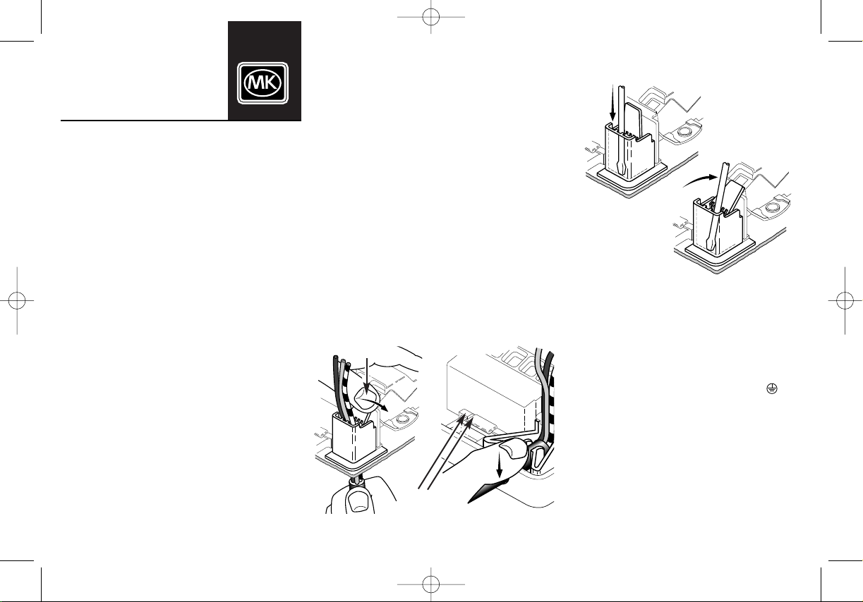
INSTALLING LOAD CABLES USING BOTTOM CABLE
CLAMP
1. Remove the plug from the cable entry point.
2. Strip back the outer sheath on the appliance flexible
LOAD
cable and trim wires to 60mm in length.
3.
Carefully strip back the insulation on all three cables to
expose 13mm of the conductor.
4.
Pr
ess the outer sheath of the cable into the jaws of the
clamp with a forward and downward movement, as
illustrated in
figures 3a & 3b. The jaws must clamp on the
outer sheath.
5. The conductors should now be connected to the respective
load ter
minals as described below and shown in
figur
e 4
.
6.
Take care to select the cable with the appropriate sleeve
colour code for each ter
minal.
Figur
e 2b
Tab Pushed
This Way
Installation of flexible load cables
Figur
e 2a
Cable
Stops
Figure 1a
Figure 1b
Pre-stressing the front cable clamp for cables greater than
10mm in diameter
43468PL Ed3 2/2/2006 10:24 am Page 1
Page 2

98
11
BROWN = LOAD terminal marked ‘L’
BLUE = = LOAD terminal marked ‘N’
G
REEN/ YELLOW = LOAD terminal marked ‘ ’
I
NSTALLING SUPPLY AND NON FLEXIBLE LOAD CABLES
FOR HARD WIRED INSTALLATIONS
1. Strip back the outer sheath and trim wires to approximate
length to allow cable ends to reach terminals.
2. Carefully strip back the inner insulation to expose 13mm
of the conductor.
3. Slide a length of green/yellow sleeving onto the bare
earth conductor.
4. Connect the cables to the correct
SUPPLY or LOAD
terminals, as shown in figure 5.
5. A length of green/yellow sleeved conductor must be
connected between the product and the earth terminal in
the back box.
6. Please note; the colour codes used in the UK prior to
April 2004 are as follows: -
In all other areas of the EU, as well as new build installations
in the UK after April 2004, the colour codes used ar
e: -
The first colour indicated in the following illustrations will be
that used prior to April 2004. The second colour, shown in
brackets, is the colour used after April 2004.
7. Using the fixing screws provided, mount the product onto
the back box. Do not over tighten, so as to prevent
damage or distortion to the front plate. Adjust so the
front plate is square on the wall.
8.
If the product has a decorative clip-on front plate, hook
the plate on the clips down the left hand side of the
product and apply figure pressure down the right hand
side until the plate is hear
d to click into place.
10
Note: Certain products in the range have no cable entry and
are designed for 'hard' wired installations only.
H
owever, when a bottom entry product is used in a 'hard'
wired position, the blanking plug must be left in place in the
bottom edge of the front plate.
The cable clamp is not used when there are no external
flexible cables.
CHANGING FUSES ON CONNECTION UNITS
1. Unscrew the fuse carrier screw to partially eject the
carrier.
2. Carefully lever the carrier out further to remove the fuse.
Note: The carrier does not come fully out.
3. Always replace with a BS 1362 type fuse (as used in 13A
plugs) of the correct rating.
4.
Consistent fuse blowing could mean a faulty appliance. If
in doubt, consult a qualified electrician.
5.
Push carrier back until engaging with jacking screw. Screw
the carrier down until flush with surface of the plate. Do
not over tighten the screw.
CLEANING FRONT PLATES
In order to protect the quality surface finish of the front plate,
periodically clean with a dry lint free soft cloth. On no
account should abrasive or domestic cleaners be used.
RED = terminal marked ‘L’
BLACK = terminal marked ‘N’
GREEN/ YELLOW = terminal marked ‘ ’
BROWN = terminal marked ‘L’
BLUE = terminal marked ‘N’
GREEN/YELLOW = terminal marked ‘ ’
SUPPLY
NL
LOAD
ELNLNE
NL
Cable Grip Jaws
Cable
Grip
Load
Green/
Yellow
Blue
Brown
SUPPLY
NL
LOAD
ELNLNE
NL
Figure 5
Supply
Load
Green/
Yellow
Sleeved
Black
(Blue)
Red
(Brown)
Green/
Y
ellow
Sleeved
Black
(Blue)
Red
(Brown)
Fig 3a Installation of bottom cable outlets Fig 3b
Flexible cable connections
(bottom entry clamp shown, connection same for front entry)
Supply and non flexible load cables
Figure 4
®
MK Electric
Novar ED&S Ltd
The Arnold Centre, Paycocke Road, Basildon,
Essex SS14 3EA. U.K.
Tel: +44 (0) 1268 563000
Fax: 01268 563405
(UK Sales)
Fax: +44 (0) 1268 563360 (International)
email: technical@novar.com
web site: www.mkelectric.co.uk
Technical queries should be made to:
MK Electric, Technical Sales and Services Department
The Arnold Centre, Paycocke Road, Basildon, Essex SS14 3EA
Tel: +44 (0)1268 563720 Fax: +44 (0)1268 563064
All marks in this document identified with a R or TM symbol
adjacent to the mark are Trade Marks of Novar ED&S Limited.
43468PL Ed3 2/2/2006 10:24 am Page 4
 Loading...