

Page 1
www.mkdiamond.com
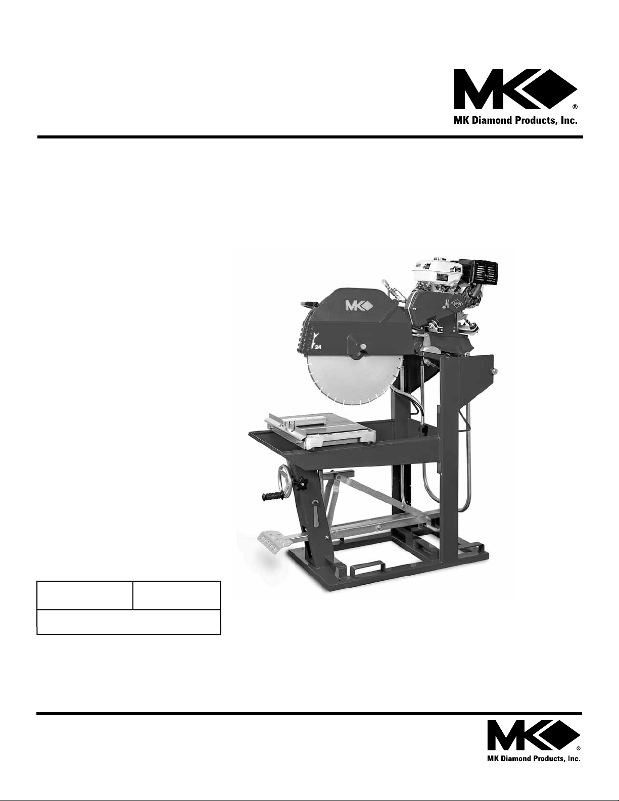
MK-5000 GAS SERIES
OWNER'S MANUAL
PARTS LIST &
OPERATING INSTRUCTIONS
Revision 105
Manual Part# 160958
Caution: Read all safety and operating instructions
before using this equipment. This parts list MUST
accompany the equipment at all times.
03.2012
Page 2
INTRODUCTION
Congratulations on your purchase of a MK-5000 Gas Block Saw. We are certain that you will be
pleased with your purchase. MK Diamond takes pride in producing the nest construction power
tools and diamond blades in the industry.
Operated correctly, your MK-5000 Gas Block Saw should provide you with years of service. In order
to help you, we have included this manual. This owners manual contains information necessary to
operate and maintain your MK-5000 Gas Block Saw safely and correctly. Please take the time to
familiarize yourself with the MK-5000 Gas Block Saw by reading and reviewing this manual.
Read and follow all safety, operating and maintenance instructions.
If you should have questions concerning your MK-5000 Gas Block Saw, please feel free to call our
friendly customer service department at: 800 421-5830
Regards,
MK Diamond
NOTE THIS INFORMATION FOR FUTURE USE:
MODEL NUMBER:
SERIAL NUMBER:
PURCHASE PLACE:
PURCHASE DATE:
NOTE: For your (1) one year warranty to be effective, complete the warranty card
(including the Serial Number) and mail it in as soon as possible.
2
Page 3

TABLE OF CONTENTS
SAFETY
Safety Messages 4
Damage Prevention Message 4
General Safety Precautions and Hazard Symbols 4
Rules for Safe Operation 7-8
California Proposition 65 Message 8
Maintenance Safety 8
Safety Label Locations 9
Brick Saw Specic Warnings 9
Product Specications 10
UNPACKING, TRANSPORT and ASSEMBLY
Unpacking 11
Contents 11
Transport 11
Assembly 12
SETUP, STARTUP, ADJUSTMENT, OPERATION and SHUTDOWN
Setup 14-15
Startup 16
Water Pump Setup 17
Cutting Setup 18-21
Operation 19-22
Cleanup 22
MAINTENANCE AND TROUBLESHOOTING
Maintenance 23-33
Troubleshooting 34-36
EXPLODED VIEW AND PARTS LIST
Exploded View & Parts List 38-52
ACCESSORIES ORDERING and RETURN INSTRUCTIONS
Accessories 53
Ordering Information 54
Return Material Policy 54
Packaging Instructions 54
Authorized Service Centers 54
Contact 55
Limited Warranty 55
3
Page 4
MK-5000G SAFETY
Safety precautions should be followed at all times when operating this equipment. Failure to read and
understand the Safety Precaution and Operating Instructions could result in injury to yourself and
others.This Operation and Parts Manual has been developed to provide complete instructions for the
safe and efcient operation of the MK-5000G Block Saw.
Before using this saw, ensure that the person operating the equipment has read and understands all instructions in this manual.
SAFETY MESSAGE / ALERT SYMBOLS
A safety message alerts you to potential hazards that could hurt you or others. Each safety message is
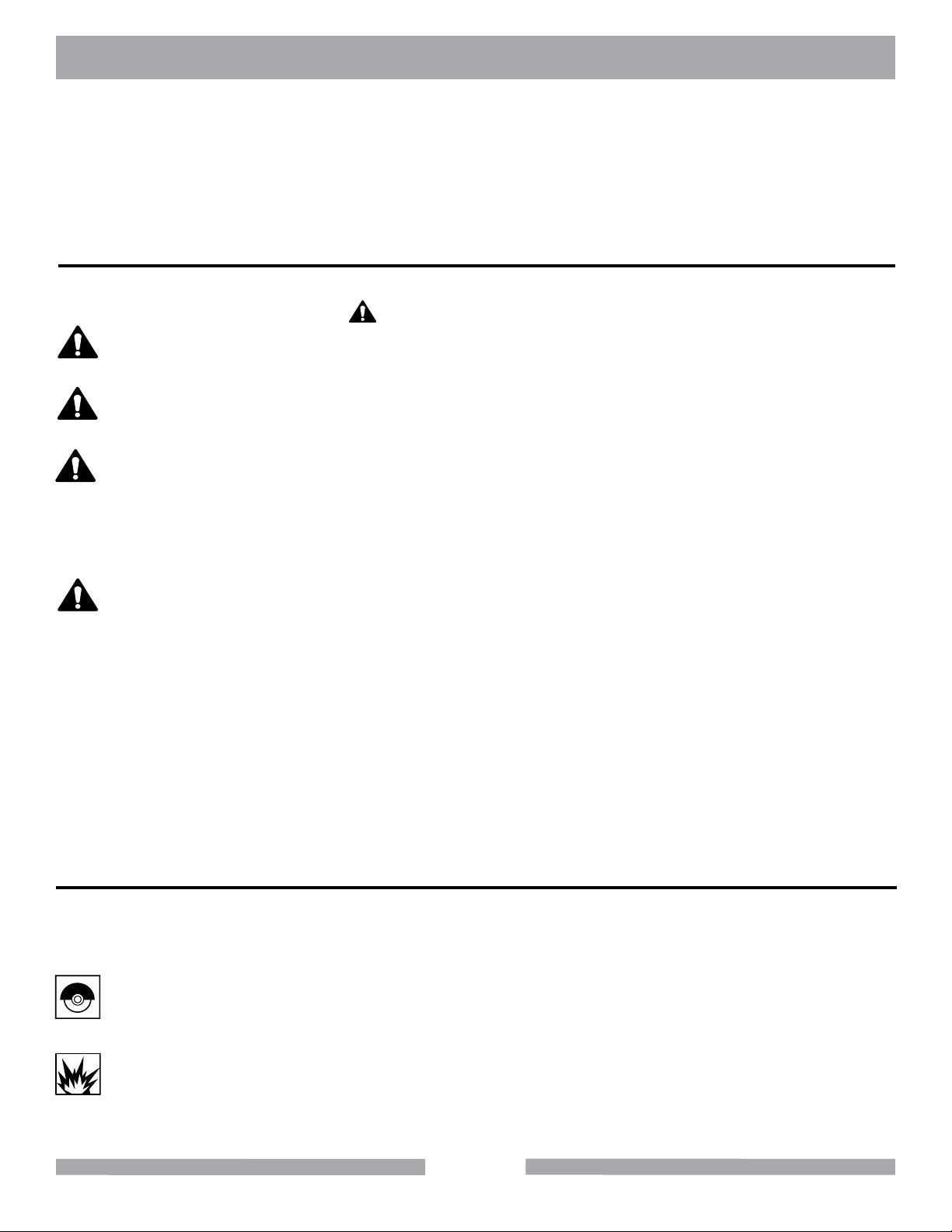
preceded by a safety alert symbol ( ) and one of three words: DANGER, WARNING, or CAUTION.
DANGER
You WILL be KILLED or SERIOUSLY INJURED if you do not follow directions.
WARNING
You CAN be KILLED or SERIOUSLY INJURED if you do not follow directions.
CAUTION
You CAN be INJURED if you do not follow directions. It may also be used
to alert against unsafe practices.
Each message tells you what the hazard is, what can happen, and what you can do to avoid or
reduce injury. Other important messages are preceded by the word NOTICE.
NOTICE
You can cause PROPERTY DAMAGE to your machine if you don’t follow directions.
The safety labels should be periodically inspected and cleaned by the user to maintain good legibility
at a safe viewing distance. If the label is worn, damaged or illegible, it should be replaced. Contact
MK Diamond or your dealer for replacement.
DAMAGE PREVENTION AND INFORMATION MESSAGES
A Damage Prevention Message is to inform the user of important information and/or instructions that
could lead to equipment or other property damage if not followed. Information messages convey
information that pertains to the equipment being used. Each message will be preceded by the word
note, as in the example below.
NOTE: Equipment and/or property damage may result if these instructions are not followed.
GENERAL SAFETY PRECAUTIONS AND HAZARD SYMBOLS
In order to prevent injury, the following safety precautions and symbols should be followed at all times!
SAFETY PRECAUTIONS
KEEP GUARDS IN PLACE
In order to prevent injury, keep guards in place and in working order at all times.
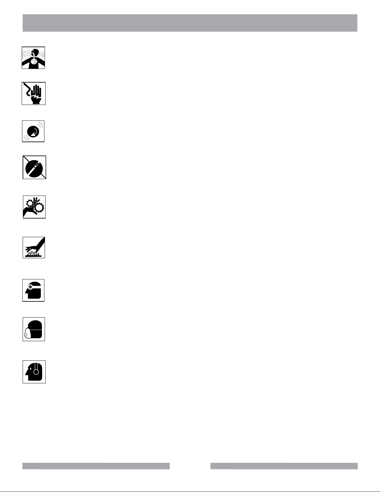
EXPLOSIVE FUEL!
Gasoline is extremely ammable, its vapors can explode if ignited; store only in approved containers, in well-ventilated, unoccupied buildings and away from sparks or ames. Do not ll the
fuel tank while the engine is running or hot. Spilled fuel could ignite if it contacts hot parts or
sparks from ignition. Do not start the engine near spilled fuel. Never use gasoline as a cleaning agent.
4
Page 5
(
(
)
)
on
MK-5000G SAFETY
LETHAL EXHAUST GASES!
Engine exhaust gasses contain poisonous carbon monoxide, an odorless colorless gas that
can cause death if inhaled. Avoid inhaling exhaust fumes, and never run the engine in a
closed building or conned area.
ELECTRICAL SHOCK!
Never touch electrical wires or components while the motor is running. Exposed, frayed or
worn electrical motor wiring can be sources of electrical shock that could cause severe injury
or burns.
ENGINE OVER-SPEED.
Never tamper with the governor components or settings to increase the maximum speed of
the machine. Severe personal injury and/or equipment damage could result if the equipment is operated speeds above design maximum.
ACCIDENTAL STARTS!
Before starting the engine, be sure the ON/OFF switch is in the “OFF” position to prevent
accidental starting. Place the ON/OFF switch in the OFF position before performing any
service operation.
ROTATING OR MOVING PARTS!
Keep hands, feet, hair, and clothing away from all moving parts to prevent injury. Never
operate a power tool with shrouds or guards removed.
HOT PARTS!
Engine components can become extremely hot from operation. To prevent severe burns, do
not touch these areas while the engine is running, or immediately after it is turned off. Never
operate the engine with heat shields removed.
ALWAYS USE SAFETY GLASSES!
Safety glasses should always be worn when working around power tools. Everyday eye-
glasses only have impact resistant lenses and may not prevent eye injury; they are NOT
safety glasses.
ALWAYS USE RESPIRATORY PROTECTION!
Exhaust gases may be harmful if inhaled. Do not operate gas-powered equipment in enclosed spaces. Respiratory protection should be worn when operating gas powered equipment.
ALWAYS USE HEARING PROTECTION!
To reduce the possibility of hearing loss, always use hearing protection when operating
equipment.
REMOVE ADJUSTING KEYS AND WRENCHES.
Form a habit of checking to see that keys and adjusting wrenches are removed from the power tool
before it is turned on.
KEEP WORK AREA CLEAN.
Cluttered work areas and benches invite accidents.
DO NOT USE IN DANGEROUS ENVIRONMENTS.
Do not operate equipment in dangerous environments. Always keep the work area well lighted.
5
Page 6

MK-5000G SAFETY
KEEP CHILDREN AWAY.
All visitors and children should be kept a safe distance from work area.
MAKE WORKSHOP KID PROOF.
Make the workshops kid proof by using padlocks, master switches or by removing starter keys.
DO NOT FORCE THE TOOL.
A power tool will do a job better and safer operating at the rate for which it was designed.
USE THE RIGHT TOOL.
Do not force a tool or an attachment, to do a job that it was not designed to do.
WEAR PROPER APPAREL.
Do not wear loose clothing, gloves, neckties, rings, bracelets, or other jewelry that may be caught in
moving parts. Nonslip footwear is recommended. Wear protective hair covering to contain long hair.
SECURE WORK.
Clamps or a vise should be used to hold work whenever practical. Keeping your hands free to operate a power tool is safer.
DO NOT OVERREACH.
Keep proper footing and balance at all times by not overreaching.
MAINTAIN TOOLS WITH CARE.
Keep tools sharp and clean for the best and safest performance. Always follow maintenance instructions for lubricating and when changing accessories.
SHUTDOWN TOOL.
The saw should always be shutdown before servicing or when changing accessories such as
blades, bits, cutters, and the like.
USE RECOMMENDED ACCESSORIES.
Consult the owner’s manual for recommended accessories. Using improper accessories may increase the risk of personal or by-stander injury.
NEVER STAND ON THE TOOL.
Serious injury could occur if a power tool is tipped, or if a cutting tool is unintentionally contacted.
NEVER LEAVE TOOL RUNNING UNATTENDED – TURN POWER OFF.
Do not leave a tool until it comes to a complete stop. Always turn a power tool OFF when leaving
the work area, or, when a cut is nished.
CHECK FOR DAMAGED PARTS.
Before using a power tool, check for damaged parts. A guard or any other part that is damaged
should be carefully checked to determine it would operate properly and perform its intended function. Always check moving parts for proper alignment or binding. Check for broken parts, mountings and all other conditions that may affect the operation of the power tool. A guard or any damaged part should be properly repaired or replaced.
6
Page 7
MK-5000G SAFETY
DIRECTION OF FEED.
Always feed work into a blade or cutter against the direction of rotation. A blade or cutter should always be installed such that rotation is in the direction of the arrow imprinted on the side of the blade or
cutter.
SILICA DUST WARNING
Grinding/cutting/drilling of masonry, concrete, metal and other materials with silica in their composition
may give off dust or mists containing crystalline silica. Silica is a basic component of sand, quartz,
brick clay, granite and numerous other minerals and rocks. Repeated and/or substantial inhalation of
airborne crystalline silica can cause serious or fatal respiratory diseases, including silicosis. In addition, California and some other authorities have listed respirable crystalline silica as a substance
known to cause cancer. When cutting such materials, always follow respiratory precautions.
Some dust created by power sanding, sawing, grinding, drilling, and other construction activities contain chemicals known (to the State of California) to cause cancer, birth defects or other reproductive
harm. Some examples of these chemicals are:
• Lead, from lead-based paints
• Crystalline silica, from bricks and cement and other masonry products
• Arsenic and chromium, from chemically treated lumber
For further information, consult the following sources:
http://www.osha.gov/dsg/topics/silicacrystalline/index.html
http://www.cdc.gov/niosh/consilic.html
http://oehha.ca.gov/prop65/law/P65law72003.html
http://www.dir.ca.gov/Title8/sub4.html
Your risk from these exposures varies depending on how often you do this type of work. To reduce
your exposure to these chemicals, work in a well-ventilated area, and work with approved safety
equipment, such as those dust masks that are specially designed to lter out microscopic particles.
RULES FOR SAFE OPERATION
DANGER
Failure to follow instructions in this manual may lead to serious injury or even death! This equipment
is to be operated by trained and qualied personnel only! This equipment is for industrial use only.
The following safety guidelines should always be used when operating the MK-5000G Block Saw.
GENERAL SAFETY
• DO NOT operate or service this equipment before reading this entire manual.
• This equipment should not be operated by persons under 18 years of age.
• NEVER operate this equipment when not feeling well due to fatigue, illness or taking
medicine.
• NEVER operate this equipment under the inuence of drugs or alcohol.
7
Page 8
MK-5000G SAFETY
• Whenever necessary, replace nameplate, operation and safety decals when they become
difcult to read.
ON / OFF
• ALWAYS store equipment properly when it is not being used. Equipment should be stored in
a clean, dry location out of the reach of children.
• NEVER leave the machine unattended. Turn off electric motor when unattended.
CAUTION must be observed while servicing the machine. Rotating parts can cause injury if contacted.
• NEVER operate the machine in an explosive atmosphere.
Before starting the machine, ALWAYS check that all guards are in position and correctly tted. Check
the machine for loose bolts before starting.
Keep area around the machine clear of obstructions which could cause persons to fall onto moving parts.
ALWAYS ensure that the machine is on level ground before using.
Know how to stop the machine quickly in case of emergency. NEVER try to stop a moving blade with
your hands.
• NEVER disconnect any “emergency or safety devices”. These devices are intended for operator
safety. Disconnection of these devices can cause severe injury, bodily harm or even death!
Disconnection of any of these devices will void all warranties.
• Unauthorized equipment modications will void all warranties. Manufacturer does not assume re
sponsibility for any accident due to equipment modications.
• NEVER use accessories or attachments, which are not recommended by MK Diamond for this
equipment. Damage to the equipment and/or injury to user may result.
WARNING
DO NOT use woodcutting, or carbide blades on this machine! Use ONLY Diamond blades on ma-
chine. Use machine only to cut tile and masonry products. DO NOT use machine to cut wood or
wood products.
MAINTENANCE SAFETY
• NEVER lubricate components or attempt service on a running machine.
• Keep the machinery in proper running condition.
• Fix damage to the machine immediately and always replace broken parts, or missing decals.
8
Page 9
MK-5000G SAFETY
OPERATION & SAFETY DECALS
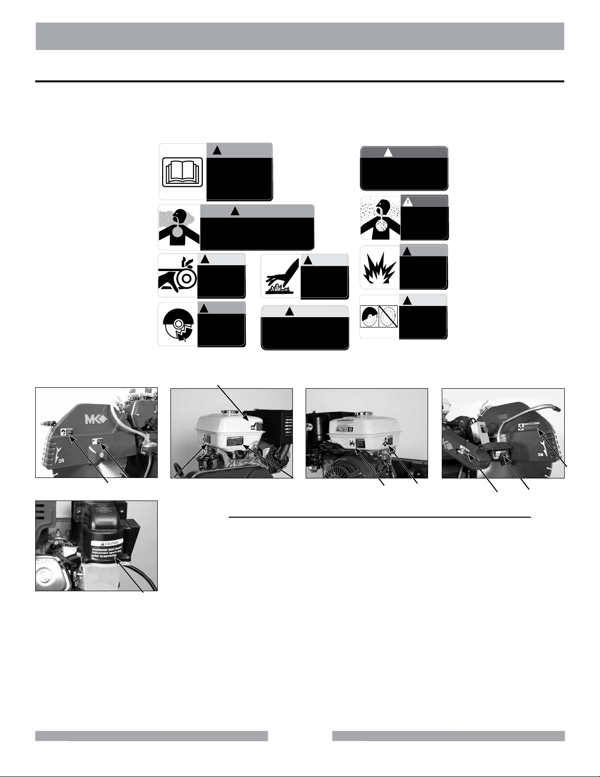
The MK-5000G Block Saw is equipped with a number of safety decals. These decals are provided for
operator safety and maintenance information. Should any of these operation or safety decals become
unreadable, replacements can be obtained by calling (800) 262-1575.
WARNING
!
(A)
(B)
(C)
(D)
DO NOT operate
this equipment
before reading
the owners’
manual!
!
WARNING
Grinding/cutting/drilling of masonry, concrete, metal and other materials with silica in
their composition may give off dust or mists containing crystalline silica. Silica is a basic
component of sand, quartz, brick clay, granite and numerous other minerals and rocks.
Repeated and/or substantial inhalation of airborne crystalline silica can cause serious
or fatal respiratory diseases, including silicosis. In addition, California and some other
authorities have listed respirable crystalline silica as a substance known to cause cancer.
CAUTION
!
DO NOT
operate without
guards in place.
WARNING
!
In the event of
blade failure,
replace blade
guard
immediately.
(H)
CAUTION
!
Accidental start hazard.
(J)
Disconnect spark plug
prior to servicing.
CAUTION
!
DO NOT
touch hot
surface.
DANGER
!
The exhaust from this product
contains chemicals known to
the State of California to cause
cancer, birth defects or other
reproductive harm.
DANGER
Lethal exhaust
gases. Use only
in well ventilated
areas. DO NOT
use indoors.
WARNING
!
When refueling
stop engine and
allow to cool.
DO NOT overll
tank.
CAUTION
!
DO NOT
operate without
guards in place.
(F)
(G)
(I)
(E)
Masonry Saw Warning Label Sheet Part# 166011
H
B
E
D
G
F
I
G
C
A
Location Description
A Arbor Housing/Front Read Manual
B Bladeguard/Back Proposition 65, Dust
Warning
C Belt Guard/Front Guards in Place
J
D Blade Guard/Front Replace Blade Guard
E Blade Guard/Front Guards in Place
F Gas Tank/Side Exhaust/Cancer
G Gas Tank/Front Lethal exhaust
H Gas Tank/Side Hot Surface
I Gas Tank/Side Filling Gas
J Engine Filter/Back Accidental Start
9
Page 10
MK-5000G PRODUCT SPECIFICATION
PRODUCT SPECIFICATIONS
The MK-5000G is a versatile gas powered Block Saw. Operated and used according to this manual,
the MK-5000G will provide years of dependable service.
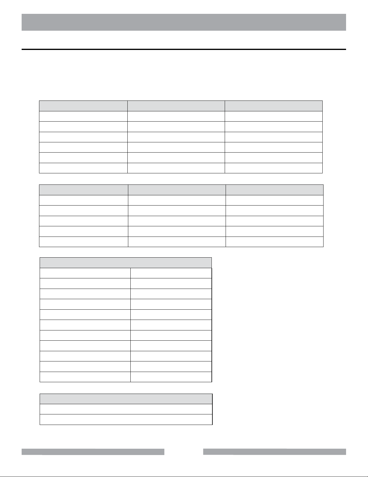
Engine Specications
Engine specications for the different models of the MK-5000G are listed in the tables below.
Model MK-5009G MK-5009G
Engine Honda Kohler
Horsepower GX270 Cyclone CH395
Part # (14" Blade Guard) 158935-14 •
Part # (20" Blade Guard) 158935 168805
Part # (24" Blade Guard) 158935-24 168805-24
Weight 498 lbs. (225 kg) 498 lbs. (225 kg)
Model MK-5010G MK-5013G
Engine Vanguard Honda
Horsepower 19H200 GX390 Cyclone
Part # (20" Blade Guard) 169338 158936
Part # (24" Blade Guard) 169338-24 158936-24
Weight 513 lbs. (233 kg) 513 lbs. (233 kg)
General Specications
Arbor Size 1"
Motor RPM 3,600
Shaft RPM (14" Blade) 2,700
Shaft RPM (20" Blade) 1,851
Shaft RPM (24" Blade) 1,653
L x W x H 57" x 26" 72"
L x W x H (mm) 1,524 x 660 x 1,826
Depth of Cut w/20" Blade 8"
Depth of Cut w/24" Blade 10"
Length of Cut 20"
Shipping Method Truck
Accessories Included with MK-5000 Series Saws
Centrifugal Water Pump
Rip Guide
10
Page 11
MK-5000G PRODUCT SPECIFICATION
Masonry Types
The MK-5000G can cut a variety of masonry types including, cinder block, slump stone block, wall
brick, paver brick, concrete block and cylinders, roong tile, marble, granite, decorative rock or almost
any other non-ferrous material.
The MK-5000G is not designed to cut plastic or ferrous (metals) material. NOTE:
Spring Assisted Cutting Head
The MK-5000G is designed with a spring-assisted cutting head to allow for easier step cutting. The
Cutting Head can be locked in the down position when cutting smaller pieces.
Shaft Operated Water Pump
The MK-5000G has a exible shaft, belt driven water pump supplying cooling water to the blade for
wet cutting operations.
UNPACKING
Your MK-5000G has been shipped from the factory thoroughly inspected. Only minimal assembly is
required. If not done, completely remove the plastic wrapping from the MK-5000G. Remove the accessories box from the Water Basin and remove the contents from the box.
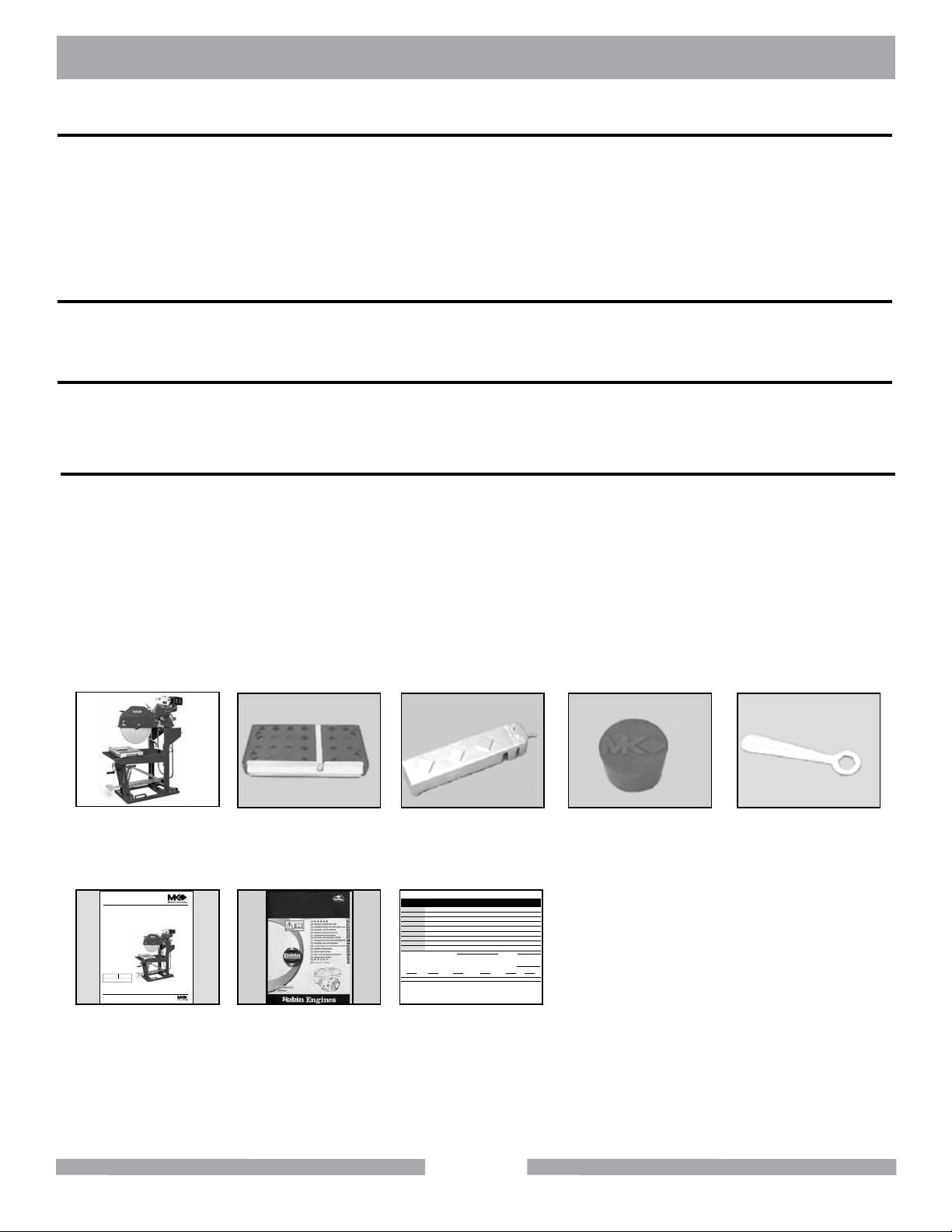
CONTENTS
In your container, you will nd one (1) MK-5000G, one (1) movable cutting table, one (1) adjustable
cutting guide, one (1) drain plug, one (1) blade wrench, one (1) owner’s manual, one (1) Engine
owner’s manual and one (1) warranty card.
MK-5000G
Block Saw
www.mkdiamond.com
Revision 100
Manual Part# 160958
Caution: Read all safety and operating instructions before
using this equipment. This parts list MUST accompany the
equipment at all times.
09.2009
MK-5009G/5013G
OWNERS MANUAL
PARTS LIST &
OPERATING INSTRUCTIONS
MK Diamond Products, Inc.
Owner's Manual
Movable Cutting
Table
Engine Owner's
Manual
Cutting Guide Drain Plug Blade Wrench
MK DiaMonD Warranty CarD
Name
address
City
state zip Code
phoNe Fax
e-mail
produCt model
part NumBer
maChiNe serial#
where did you purChase this saw From ? N a me
q tile distriButor q home CeNter q equipmeNt supply house
q tool supply q Bldg material supply q reNtal equipmeNt house
q or CoNtraCtor q IF so, what type? tile q masoNry q other
are you a do-it-yourselFer
what Criteria was importaNt iN ChoosiNg this saw? (rate From 1 to 5, 5 BeiNg the most importaNt)
power preCisioN por taBility availaBility other
priCe
CommeNts or suggestioNs:
mK diamoNd warraNty
1315 Storm Parkway, Torrance, CA 90509 USA | www.mkdiamond.com | 1.800.421.5830 | 1.310.539.5158
If within one (1) Year from the date of purchase, this MK Diamond saw fails due to defect in material or workmanship, MK will repair it, free of charge when the unit is returned to the dealer where it was purchased. This warranty DOES NOT cover normal wear or damage resulting from operator abuse. In no event shall MK Diamond Products,
Inc. be liable for consequential damages arising out of the failure of any product if operated improperly. MK Diamond Products may act as a warranty station for motor/engine repairs based on an individual agreement with the manufacturer. This warranty is in lieu of all other warranties express or implied.
©2010 All Rights reserved. MK Diamond Products, Inc. • P/N 155037 MK Warranty Card (02/10)
date purChased
Warranty Card
11
Page 12
MK-5000G UNPACKING & TRANSPORT
TRANSPORT
CAUTION
NOTE:
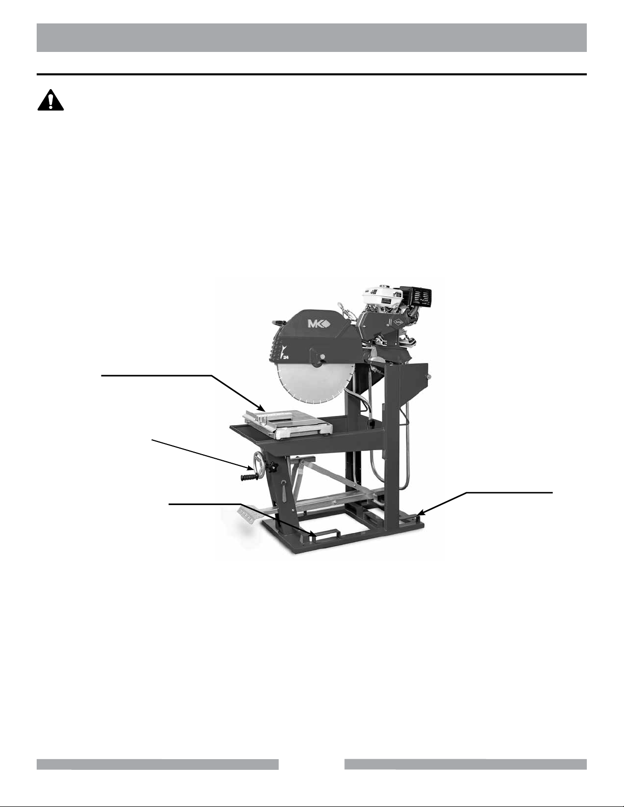
The MK-5000G is designed with forklift ears for ease of transport. To transport –
• Verify the Movable Cutting Head is locked in the down position and the Movable Cutting Table
is removed.
• Lift and transport the saw to the desired work location.
1. Never transport the MK-5000G with water in the Water Basin.
2. The MK-5000G series Block Saw weighs approximately 515 pounds, a forklift
should be used for transport.
Lock the Cutting Head in the DOWN position, and remove the Movable Cutting Table
when transporting the MK-5000G.
Remove Movable
Cutting Table
Cutting Head
Locked Down
Lift Point
Lift Point
12
Page 13
MK-5000G ASSEMBLY
ASSEMBLY
Follow the assembly instructions to prepare your MK-5000G for operation.
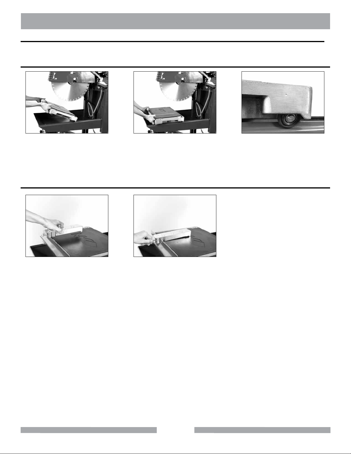
Movable Cutting Table Installation
(A)
Position Movable Cutting Table.
Seat all four Roller Wheels on
Adjustable Cutting Guide Installation
(A)
Loosen the Thumbscrew. Align
the Adjustable Cutting Guide
above the Movable Cutting Table
Ruler/Stop.
Guide and tighten the Thumb-
(B)
the Guide Rails.
(B)
Seat the Adjustable Cutting
screw.
(C)
Verify correct seating of Roller
Wheels.
13
Page 14
MK-5000G ASSEMBLY
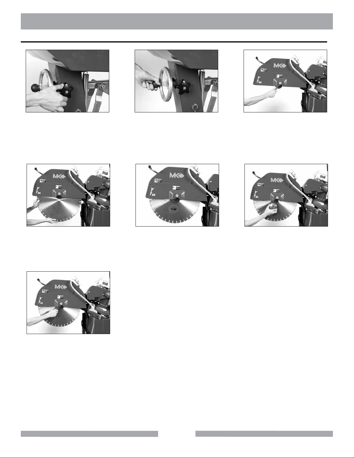
Diamond Blade Installation
(A)
Unlock Cutting Head.
(D)
Install the Diamond Blade onto
the Blade Shaft.
(B)
Raise the Cutting Head by
turning the Depth Control Wheel
clockwise.
(E)
Verify the Blade is seated on
the Blade Shaft and direction of
rotation is correct.
(C)
Remove the Retaining Screw
and Outer Flange with the blade
wrench. Turn counter-clockwise
to loosen.
(F)
Install Retaining Screw and
Outer Flange.
(G)
Rotate Blade Wrench clockwise
to tighten.
14
Page 15
MK-5000G SETUP
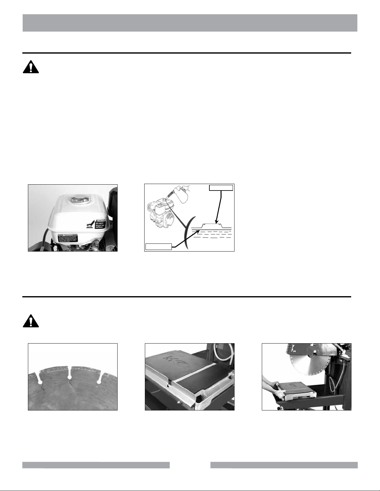
Filling Fuel Tank
WARNING
1. Gasoline is highly ammable and explosive. You can be burned or seriously injured when
handling fuel.
2. To fuel, stop engine if running, and allow it to cool.
3. Refuel in a well-ventilated area.
4. Keep gasoline away from appliance pilot lights, barbecues, electric appliances, power tools, etc.
5. Wipe up spills immediately.
NOTE:
1. Fuel can damage paint and plastic. Be careful not to spill fuel when lling the fuel tank.
Damage caused by spilled fuel IS NOT covered under the warranty.
2. DO NOT use stale or contaminated gasoline, or an oil/gasoline mixture.
3. Using a ladder meeting OSHA specication is recommended.
4. Use unleaded gasoline with a pump octane rating of 86 or higher.
Fill Throat
Upper Limit
(A)
To ll Fuel Tank refer to refueling
section of Engine Manual.
Verify fuel level is below the
throat of the Fuel Tank.
(B)
Pre-start Inspection
The pre-start inspection should be performed before beginning any job.
CAUTION
If the Diamond Blade shows signs of fatigue cracking, replace the blade before
starting work.
(A)
Inspect Blade for damage –
Verify Blade is correct for
material being cut.
(B)
Inspect Wooden Strip for
excessive grooves.
15
(C)
Verify Movable Cutting Table
moves freely.
Page 16
MK-5000G SETUP
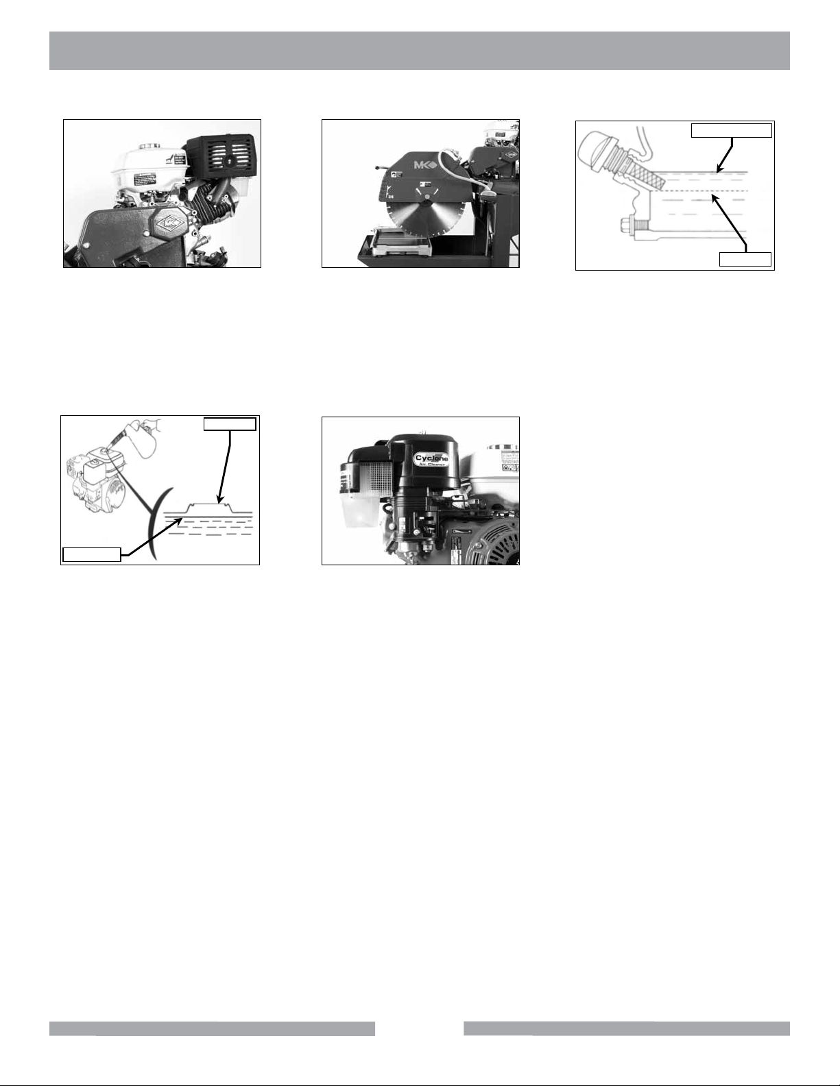
Proper Oil Level
Low Level
(D)
Inspect Engine for leaks.
Fill Throat
Upper Limit
(G)
Check for proper fuel level.
(See Maintenance section if low)
(E)
Inspect for general damage,
loose connections and hardware.
(H)
Check Air Filter for cleanliness.
(See Maintenance section if
dirty)
(F)
Check for proper oil level.
(See Maintenance section if low)
16
Page 17
MK-5000G STARTUP
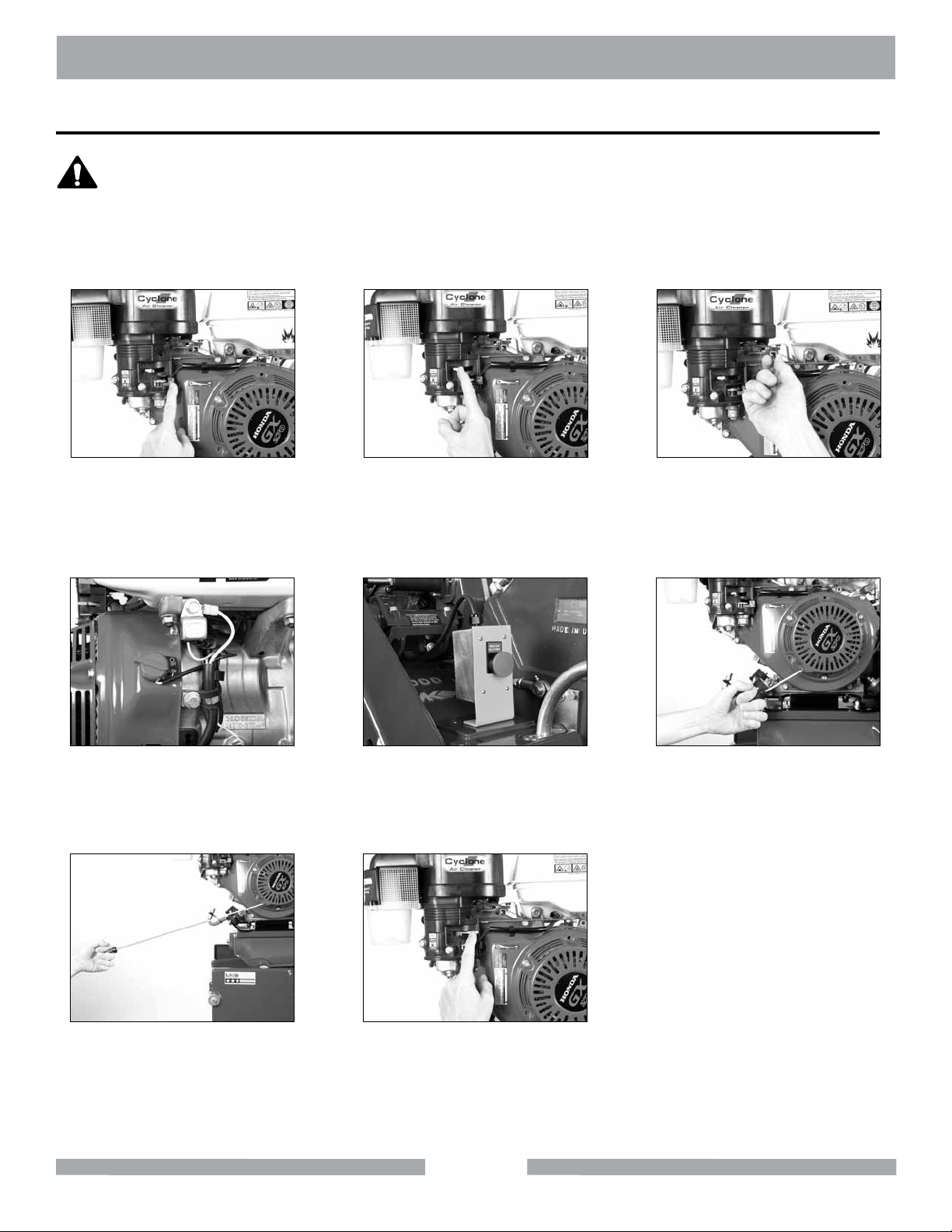
Engine Start
WARNING
1. Carbon monoxide gas is toxic. Breathing it can cause unconsciousness
and/or death.
2. Avoid any areas or actions that expose you to carbon monoxide.
If restarting a warm engine leave the Choke Lever in the OPEN position. NOTE:
(A)
Place Fuel Valve in the
ON position.
(B)
Place Choke Lever in the
CLOSED position.
(C)
Move the Throttle Lever
to 1/3 open.
(D)
Place Engine Switch in the
ON position.
(G)
Pull Starter Cord straight back
in a smooth fast motion.
(E)
Turn on Emergency Stop
Switch.
(H)
Place Choke Lever in the OPEN
position when engine is warm.
17
(F)
Pull Starter Cord slowly, until
slack is removed and
resistance is felt.
Page 18
MK-5000G SETUP
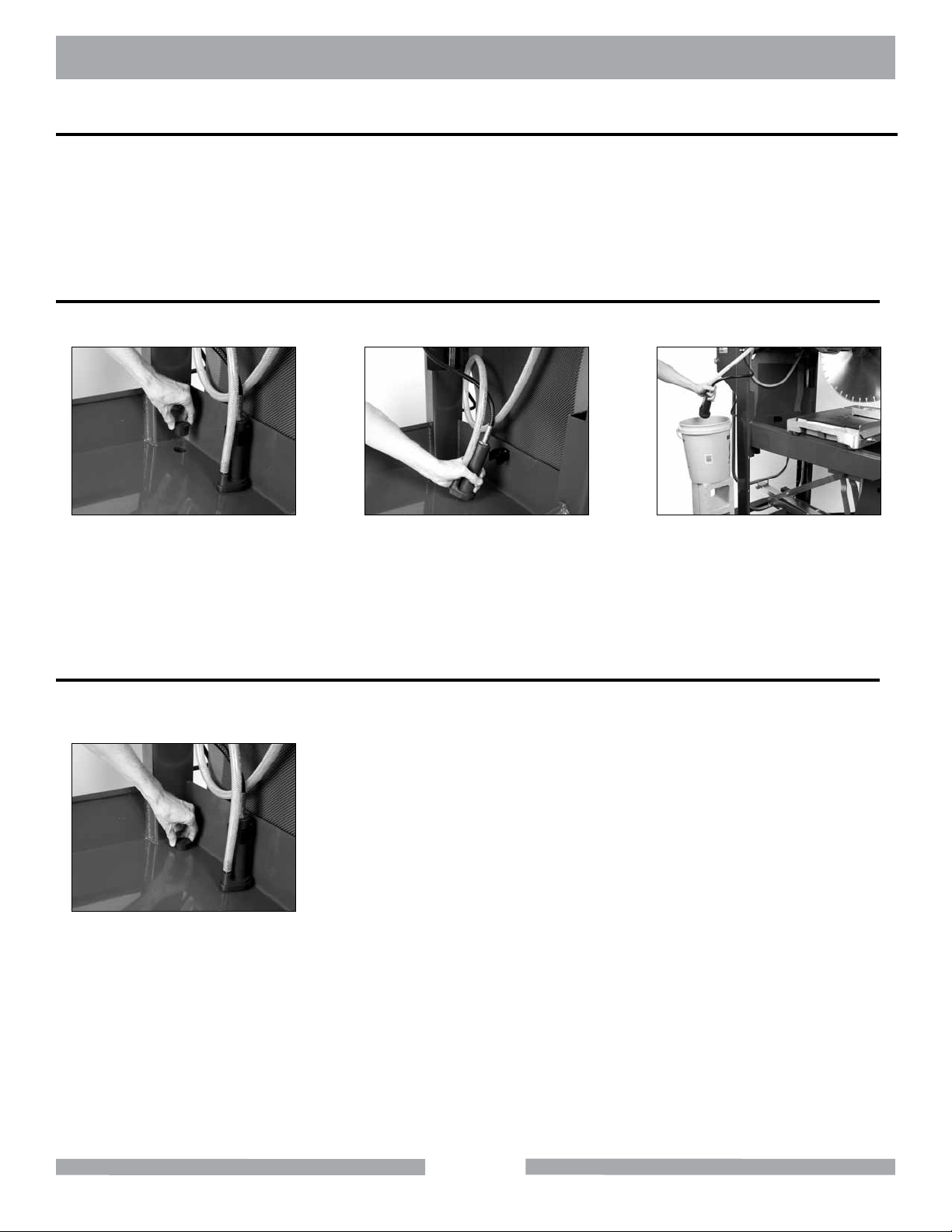
Water Pump Setup
Water Pump is factory installed and is setup for re-circulating wet cutting. If dry cutting, be sure to
disengage water pump. The Water Pump can be setup in three ways, External Water Source, Recirculation or Un-coupled for dry blade operation.
NOTE:
To extend the life of the Diamond Blade and Water Pump, MK Diamond recommends a
clean cooling water source when using a Wet Diamond Blade.
External Water Source
This is the preferred method of cooling when using a “wet” diamond blade.
(A)
Remove the Drain Plug.
Remove Water Pump.
(B)
Assembly into an external water
source container. Fill the external
water source container and place a
catch basin below the Drain Hole.
Re-circulation
(C)
Place the Water Pump
NOTE:
1. Water Pump could interfere with masonry being cut.
2. Water should be periodically replaced when using this method.
(A)
Install the Drain Plug. Fill the
water basin with clean water.
18
Page 19
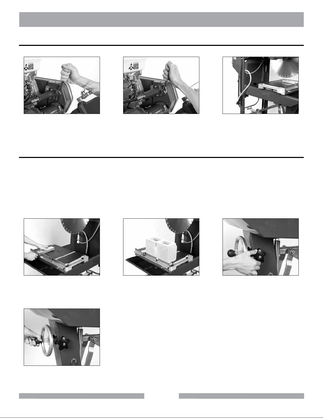
MK-5000G SETUP
Dry Blade Operation
Failure to perform the following steps will lead to premature pump failure. NOTE:
(A)
Loosen Water Pump Drive End
Pivot Plate front and rear
retaining bolts.
Cutting Setup
NOTE:
1. While the MK-5000 can cut the materials listed earlier in this document, it is specically
designed to cut
concrete masonry. Cutting another material will reduce the life of the diamond blade.
2. Due to the material being cut, the diamond blade should not require dressing. If dressing is required, use a soft stone such as sandstone.
DO NOT FORCE the blade to cut, it will do the job better and safer at rate for
which it was designed.
(B)
Pivot front of Water Pump Drive
End Pivot Plate up and tighten
the retaining bolts.
(C)
Move Water Pump Assembly
to the outside of the
Water Basin.
(A)
Set edge of Cutting
Guide to desired cut length on
Ruler/Stop.
(D)
Adjust the height of the Cutting
Head as necessary.
(B)
Set material against
Adjustable Cutting
Guide and Ruler/Stop.
19
(C)
Unlock the Cutting Head.
Page 20
MK-5000G OPERATION
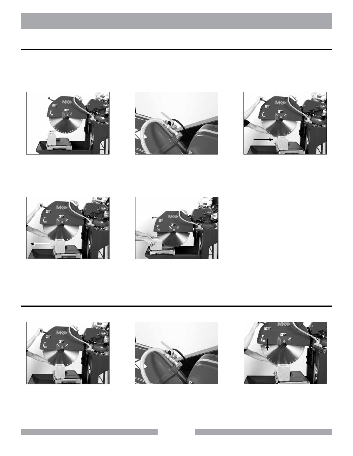
Step Cuts
A Step Cut is performed when a series of small cuts of increasing depth are used to complete a single cut.
NOTE:
1. Step Cutting is the preferred cutting method for all cuts.
2. When cutting hard material Step Cutting should always be used.
3. Step Cutting will extend the life of the Diamond Blade.
(A)
Adjust the height of the Cutting
Head as necessary, start engine.
(B)
Open the Cooling Flow Control
Valve and adjust ow. Verify
proper cooling ow on both
sides of the blade.
(C)
Step Cut "Push" Stroke. Lower
Cutting Head 1/4" -1/2"
during Push Stroke.
(D)
Step Cut "Pull" Stroke. Lower
Cutting Head and pull Cutting
Table forward.
Repeat Steps C and D until cut
is complete. Turn the saw off
when work is complete.
(E)
Chop Cutting
A Chop Cut is performed by cutting completely through an object in one pass.
(A)
Adjust the height of the Cutting
Head as necessary, start engine.
Open the Cooling Flow Control
Valve and adjust ow. Verify
proper cooling ow on both
sides of the blade.
(B)
Hold the Movable Cutting Table
stationary. Lower Cutting
20
(C)
Head smoothly to cut.
Page 21
MK-5000G OPERATION
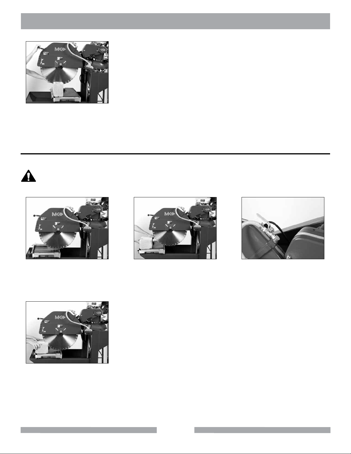
(D)
Continue Lowering Cutting Head
until cut is complete. Turn the
saw off when work is complete.
Cutting with the Cutting Head Positioned Down
This method is preferred when cutting small objects.
CAUTION
DO NOT FORCE TOOL, it will do the job better and safer at rate for which it
was designed.
(A)
Lower the Cutting Head until the
blade is just off the surface of
the Movable Cutting Table.
(B)
Set masonry piece in position.
Start engine.
(C)
Open the Cooling Flow Control
Valve and adjust ow. Verify
proper cooling ow on
both sides of the blade.
(D)
Slowly push piece toward Blade
to cut. Allow Blade to stop before
removing work. Turn the saw off
when work is complete.
21
Page 22
MK-5000G OPERATION
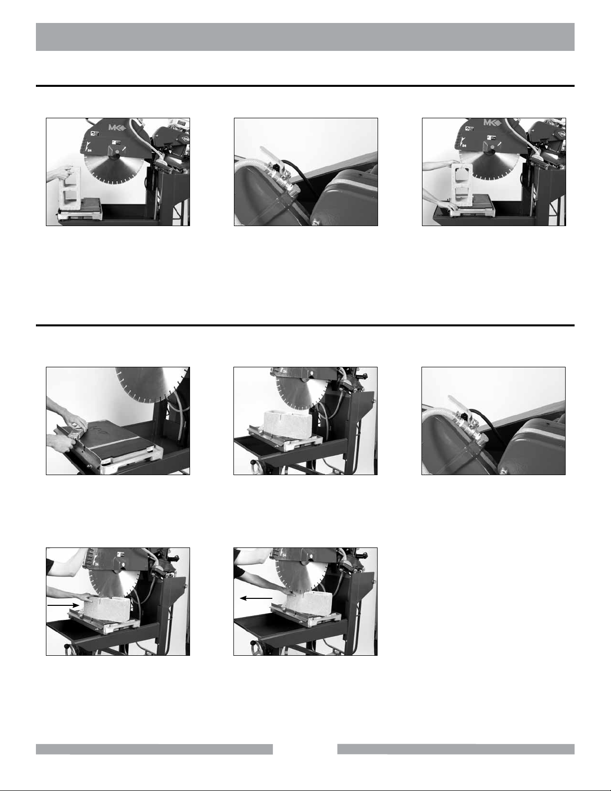
Cutting with the Piece Positioned Vertically
This method may be used when “notching” the masonry piece.
(A)
Position masonry piece.
Adjust the height of the Cutting
Head as necessary, start engine
(B)
Open the Cooling Flow Control
Valve and adjust ow. Verify
proper cooling ow on
both sides of the blade.
Slowly push piece toward Blade
to begin the cut. Continue push-
ing piece into Blade until cut is
complete. Turn the saw off when
work is complete.
(C)
Angle Cuts
Angle Cuts may be performed using the Step Cut, Chop Cut, Cutting Head Positioned Down methods
or with the masonry piece positioned vertically. The following example utilizes the Step Cut method.
(A)
Reposition Adjustable Cutting
Guide. Align 45° Slots to Ruler/
Stop.
(B)
Position the masonry piece.
Adjust the height of the Cutting
Head as necessary, start engine.
Open the Cooling Flow Control
Valve and adjust ow. Verify
proper cooling ow on
both sides of the blade.
(C)
(D)
Step Cut "Push" Stroke. Lower
Cutting Head 1/4" -1/2"
during Push Stroke.
(E)
Step Cut "Pull" Stroke. Lower Cut-
ting Head 1/4" -1/2" during Pull
Stroke. Repeat Steps D and E until
cut complete. Turn the saw off when
work is complete.
22
Page 23
MK-5000G OPERATION
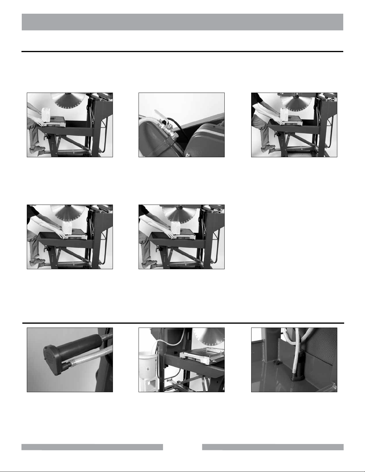
Cutting using the Foot Pedal
The Foot Pedal may be used to Step Cut, Chop Cut, or with the masonry piece positioned vertically.
Using the Foot Pedal frees both of the operator’s hands for holding the masonry piece. The following example utilizes the Step Cut method.
(A)
Position masonry piece.
Adjust the height of the Cutting
Head as necessary, start engine.
(D)
Step Cut "Pull" Stroke. Lower
Cutting Head 1/4" -1/2"
during Pull Stroke.
CLEANUP
(B)
Open the Cooling Flow Control
Valve and adjust ow. Verify
proper cooling ow on
both sides of the blade.
(E)
Repeat Steps C and D until cut
complete. Turn the saw off when
work is complete.
(C)
Step Cut "Push" Stroke. Lower
Cutting Head 1/4" -1/2"
during Push Stroke.
(A)
Clean the Water Pump
suction of all debris.
(B)
Place the Water Pump in an ex-
ternal container of clean water.
Run the saw until clear water is
seen at the blade cooling ports
(Approx. 1 minute).
23
(C)
Clean the Water Basin.
Page 24
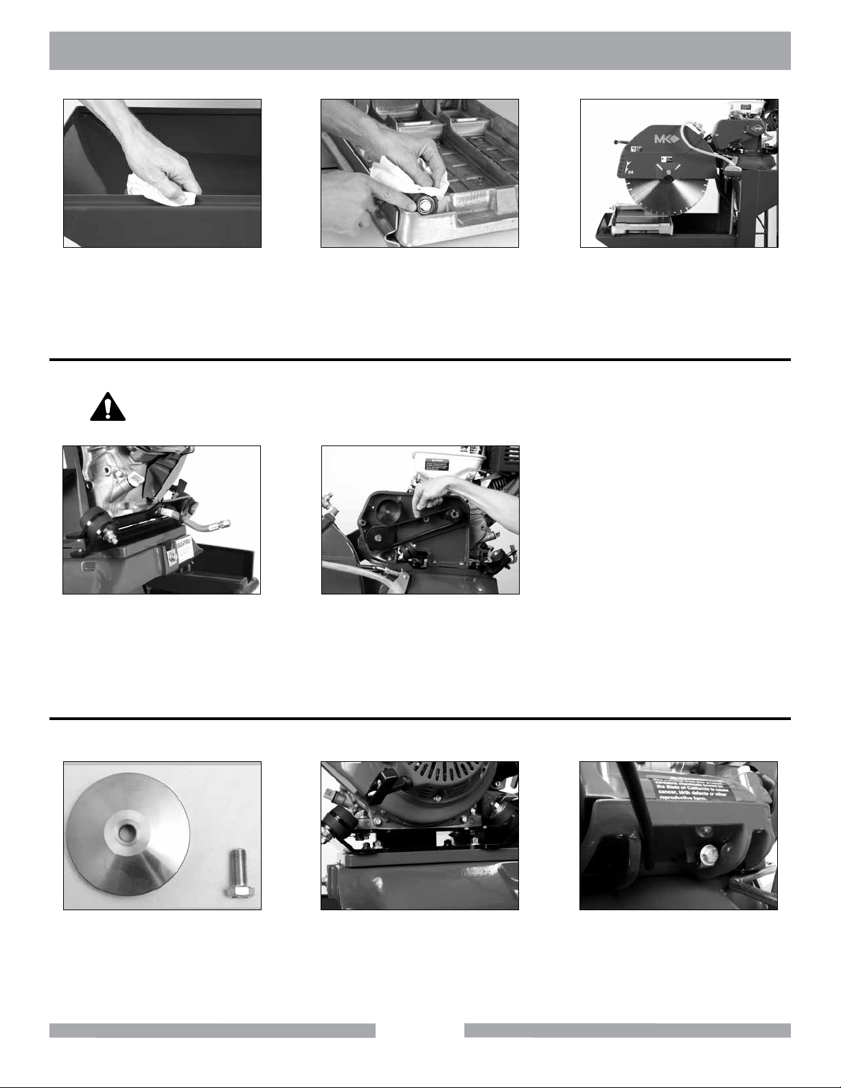
MK-5000G MAINTENANCE
(D)
Clean the Movable Cutting
Table Guide Rails.
Clean the Movable
Cutting Table Roller Wheels.
(E)
MAINTENANCE
Initial Maintenance
WARNING
Turn engine off before servicing saw.
Perform the following after initial purchase and operation of the MK-5000.
(A)
Change engine oil after rst
month or rst 20 operating
hours. (See Engine Oil Change)
Check and adjust the Blade
Shaft Belt and Jack Shaft belt
tension following rst 48 hours of
operation. (See Belt Inspection)
(B)
(F)
Clean the remainder of the saw.
Monthly Maintenance
The following should be performed monthly. Items should be lubricated as directed.
(A)
Remove and clean Diamond
Blade Outer Flange and
Retaining Bolt.
Verify all Engine Mounting
(B)
Bolts are tight.
24
Verify engine Adjustment
Straps are tight.
(C)
Page 25
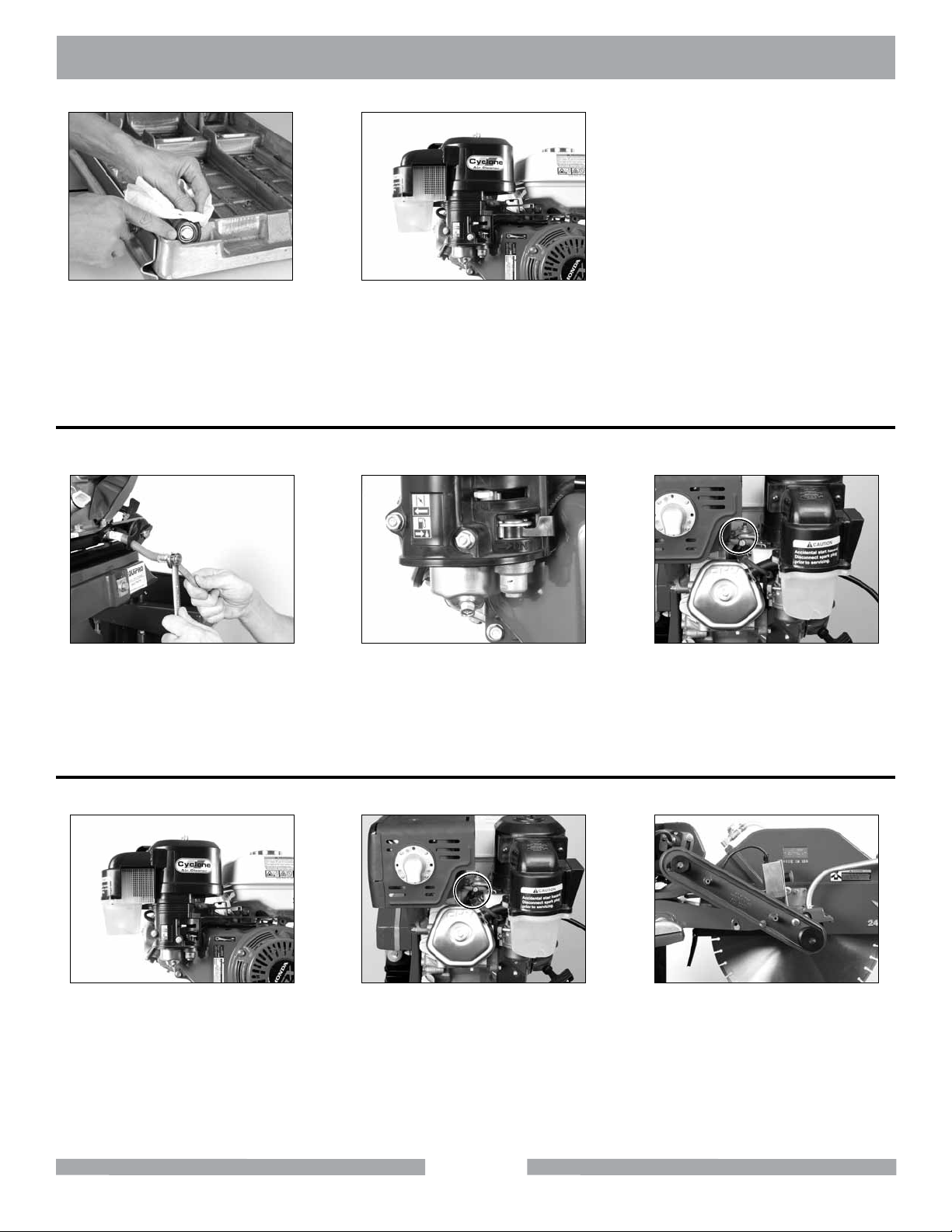
MK-5000G MAINTENANCE
(D)
Check Movable Cutting Table
Roller Wheels for wear.
Clean engine Air Filter.
(See Engine Manual)
(E)
Six (6) Month Maintenance
Perform the following maintenance every six months.
(A)
Change engine oil.
(See Engine Manual)
Clean Fuel Sediment Cup.
(See Engine Manual)
(B)
(C)
Clean and readjust engine
Spark. Plug (See Engine
Manual)
Yearly Maintenance
Perform the following maintenance every year.
(A)
Replace engine Air Filter.
(See Engine Manual)
Replace Spark Plug.
(See Engine Manual)
(B)
25
(C)
Inspect belts.
(See Belt Inspection,
Adjustment and Replacement)
Page 26
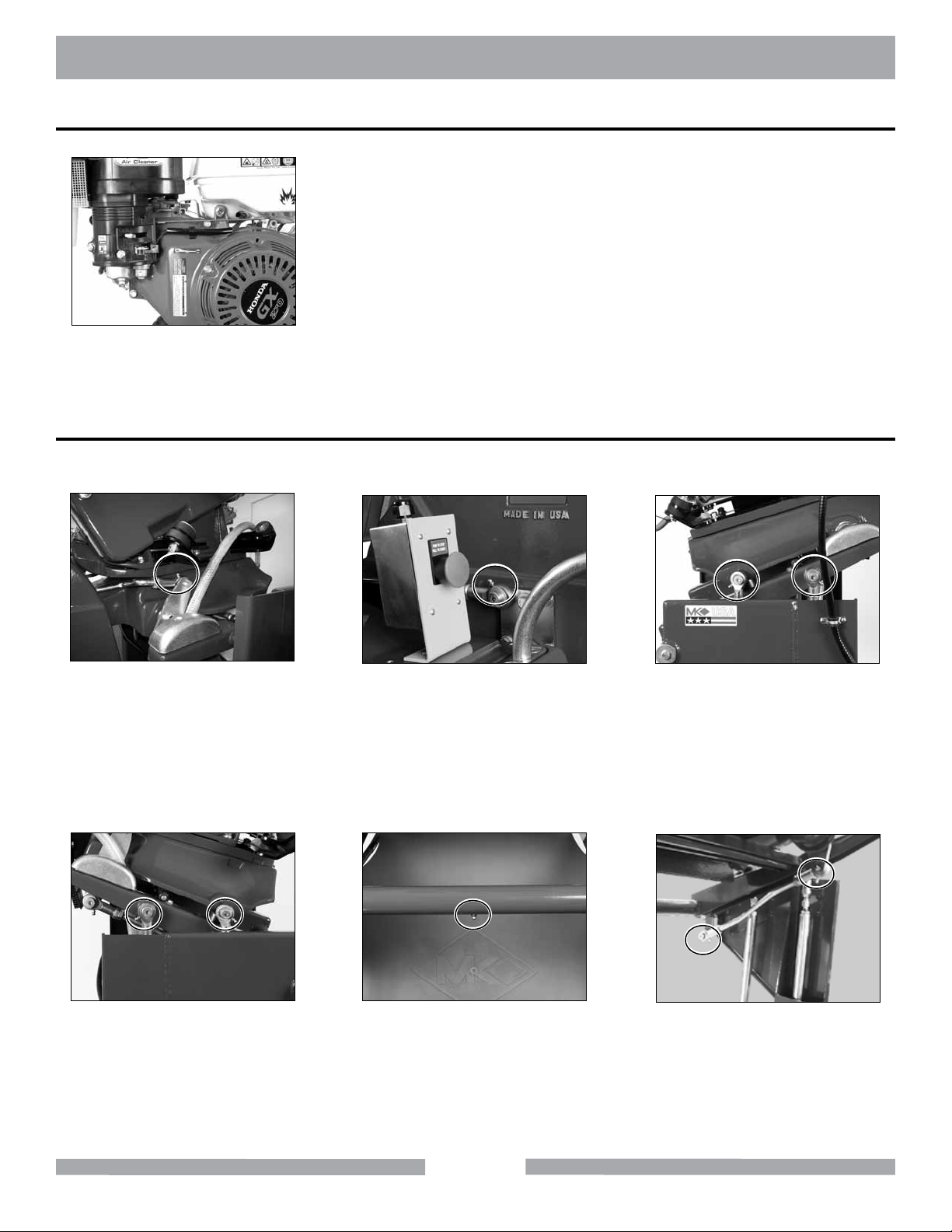
MK-5000G MAINTENANCE
Two Year Maintenance
(A)
Check Fuel Line.
(Shop Maintenance Required)
Lubrication Points
Use standard grease when lubricating the MK-5000. Clean the Zerk tting when nished lubricating.
Apply grease slowly; stop when grease is seen between joints.
(A)
Rear Blade Guard Stay-level
pivot point lubrication point, if
equipped.
(D)
Front and Rear Connecting
Arms, right side lubrication
points, if equipped.
(B)
Front Blade Guard Stay-level
pivot point lubrication point, if
equipped.
(E)
Elevation Pivot Bracket, Pivot
Shaft Housing lubrication point.
(C)
Front and Rear Connecting
Arms, left side (from front) lubri-
cation points, if equipped.
(F)
Cutting Head Rear Connect-
ing Arm lubrication point, if
equipped.
26
Page 27
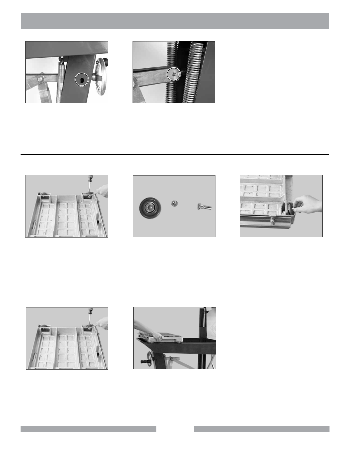
MK-5000G MAINTENANCE
(G)
Crank Wheel Assembly Bearing
lubrication point.
Depth Control Screw Housing
Movable Cutting Table Wheel Change Out
NOTE:
Remove Roller Wheels. Rotate
counter-clockwise to loosen.
Movable Cutting Table Roller Wheels should be replaced at the same time.
(A)
Obtain Wheel replacement
parts. (See parts list)
(H)
lubrication point.
(B)
(C)
Install Wheel/Washer Assembly
into Movable Cutting Table.
NOTE:
When installing the Retaining Bolt, do not “cross-thread” and DO NOT over tighten
the Nut.
(D)
Install Roller Wheel
Retaining Nut and tighten.
Rotate clockwise to tighten.
(E)
Install Movable Cutting Table.
27
Page 28
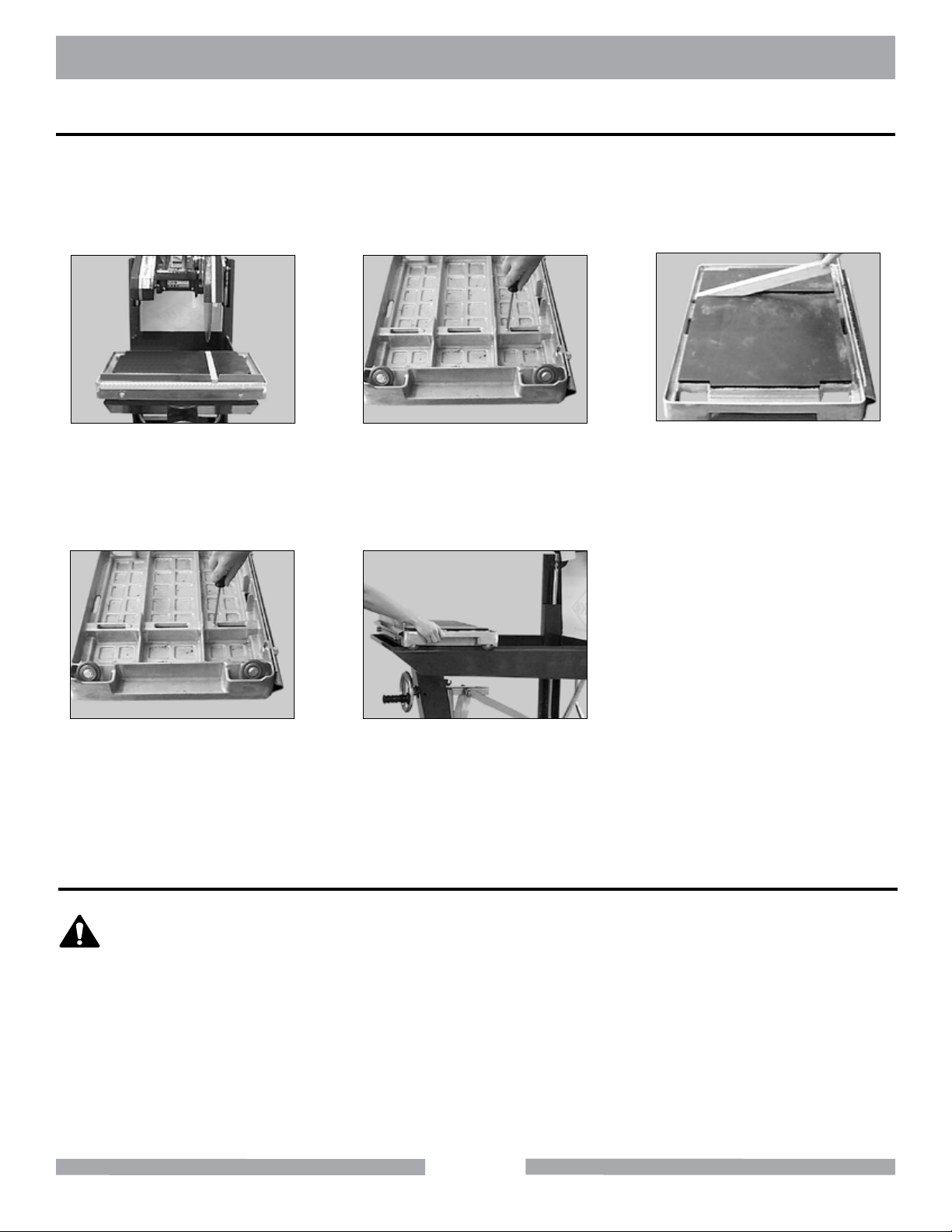
MK-5000G MAINTENANCE
Protective Wooden Strip Replacement
The protective wooden strip is to protect the Movable Cutting Table from damage during operation.
Over time, the wooden strip will become grooved from use. A grooved wooden strip will not support masonry during cutting causing the blade to “break through” the piece instead of performing a
smooth cut.
(A)
Inspect the Wooden Strip for
excessive wear and grooves.
(D)
Place Movable Cutting Table on
a work bench with the wheels
up, and reinstall retaining
screws.
Place Movable Cutting Table on
a work bench with the wheels
up. Remove the two Protective
Wooden Strip retaining screws.
Install the Movable Cutting
(B)
Replace worn
Protective Wooden Strip.
(E)
Table.
Check Fuel Level
(C)
WARNING
1. Gasoline is highly ammable and explosive. You can be burned or seriously
injured when handling fuel.
2. To fuel, stop engine if running and allow it to cool.
3. Refuel in a well-ventilated area.
4. Keep gasoline away from appliance pilot lights, barbecues, electric
appliances, power tools, etc.
5. Wipe up spills immediately.
28
Page 29
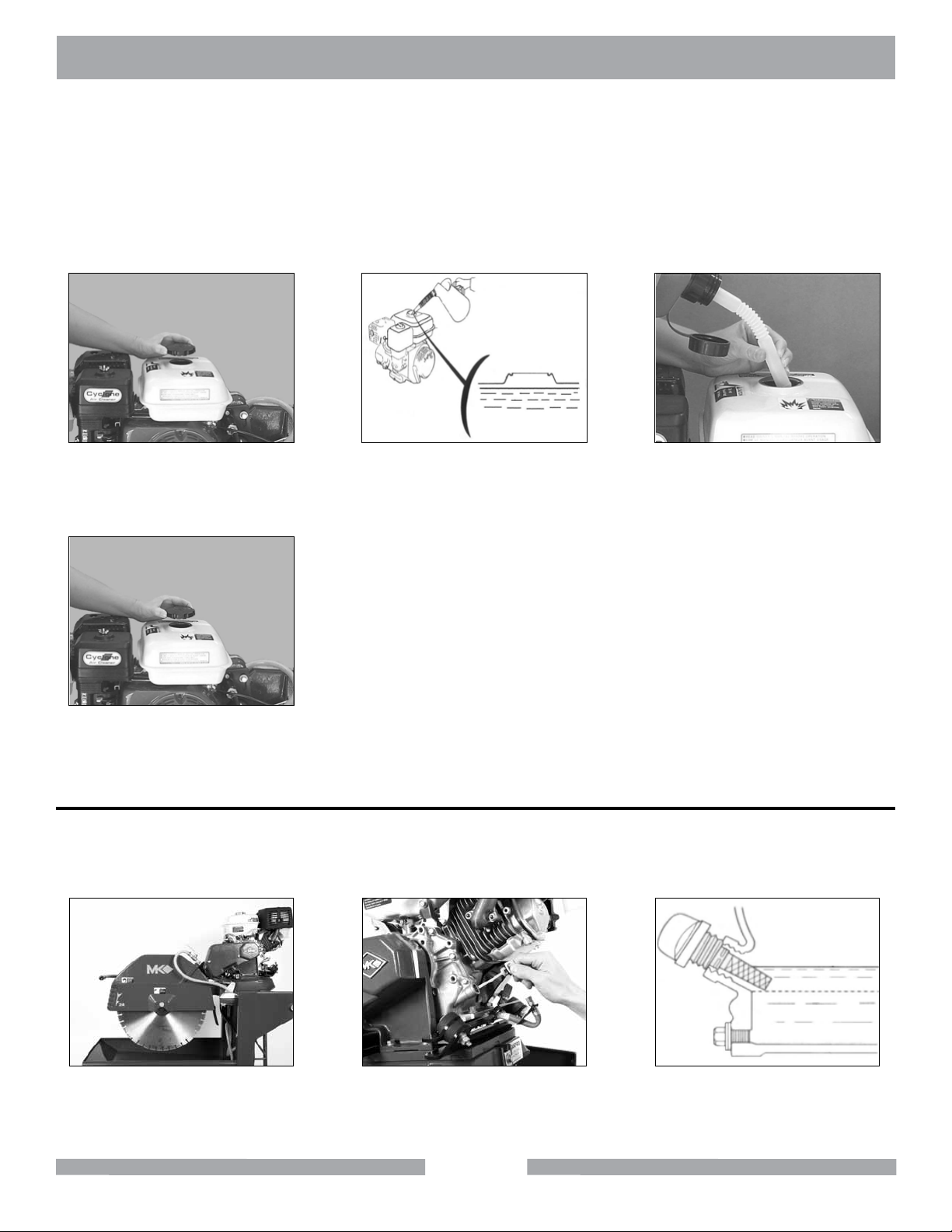
MK-5000G MAINTENANCE
NOTE:
Remove Fuel Cap.
1. Fuel can damage paint and plastic. Be careful not to spill fuel when lling the fuel tank.
Damage caused by spilled fuel IS NOT covered under the warranty.
2. DO NOT use stale or contaminated gasoline or an oil/gasoline mixture.
3. A ladder meeting OSHA specication is recommended.
4. Use unleaded gasoline with a pump octane rating of 86 or higher.
(A)
(B)
Check Fuel Level (If level is 1/2
full or greater, go to step D.
Fill Fuel Tank until level is
(C)
below throat.
(D)
Install Fuel Cap
DO NOT over-tighten.
Checking Oil Level
NOTE:
1. See Engine Manual for capacity.
2. When installing the Oil Dipstick, ensure the threads are aligned with the threads of
the Oil Reservoir so as not to “cross-thread.”
(A)
Level Cutting Head.
(B)
Remove Dipstick.
29
(C)
Check Oil Level.
Page 30
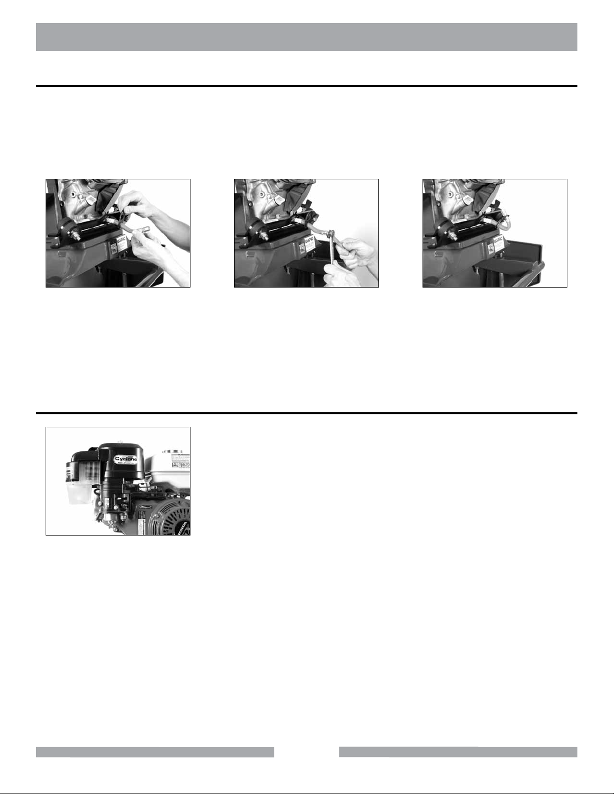
MK-5000G MAINTENANCE
Changing Oil
Oil is a major factor affecting performance and service life. See Engine Manual for specications.
NOTE:
1. Drain used oil while the engine is warm.
2. Conform to Federal, State and Local laws, codes and ordinances relative to
environmental protection for oil disposal.
(A)
Raise Cutting Head. Straighten
oil drain hose.
Place container below Oil Drain.
Open Oil Drain; Drain Oil (conform
to Federal, State and Local laws
(B)
for disposal).
Engine Air Filter Inspection Cleaning and Replacement
(C)
Fill Oil Reservoir.
(See Engine Manual)
(A)
The Air Filter needs to be
cleaned and/or replaced occa-
sionally. (See Engine Manual)
30
Page 31
MK-5000G MAINTENANCE
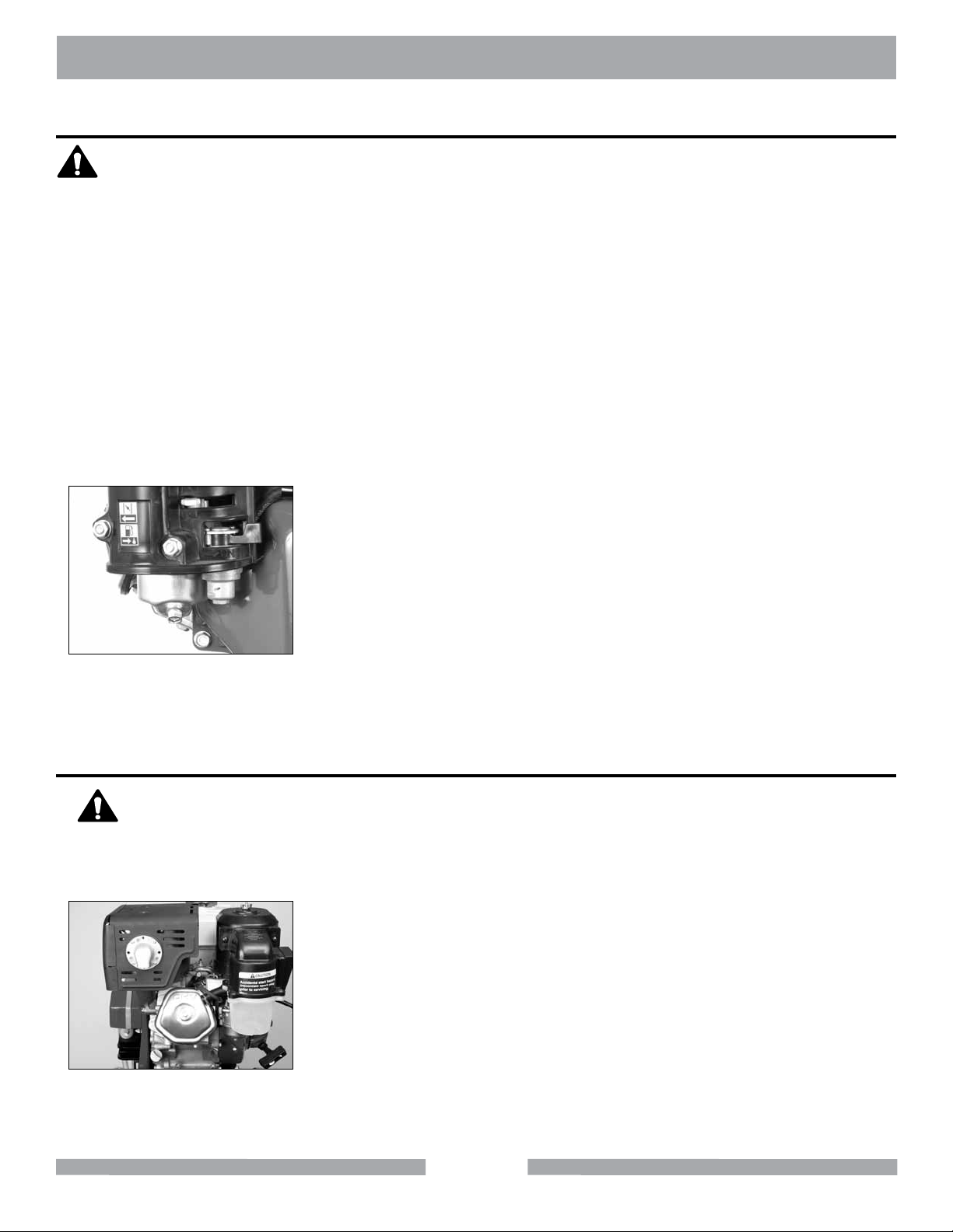
Fuel Sediment Cup Cleaning
WARNING
NOTE:
1. Gasoline is highly ammable and explosive. You can be burned or seriously
injured when handling fuel.
2. To fuel, stop engine if running and allow it to cool.
3. Refuel in a well-ventilated area.
4. Keep gasoline away from appliance pilot lights, barbecues, electric
appliances, power tools, etc.
5. Wipe up spills immediately.
1. Conform to Federal, State and Local laws for the proper disposal of fuel
2. Fuel can damage paint and plastic. Be careful not to spill fuel when lling the fuel tank.
Damage caused by spilled fuel IS NOT covered under the warranty.
3. DO NOT use stale or contaminated gasoline or an oil/gasoline mixture.
4. An OSHA approved ladder is recommended when fueling.
5. When installing the Sediment Cup retaining bolt, ensure the threads of the bolt are
aligned with the threads on the Fuel Valve so as not to “cross-thread the bolt.”
(A)
The fuel sediment cup needs to
be cleaned occasionally.
(See Engine Manual)
Spark Plug Replacement
CAUTION
NOTE:
1. When installing the Spark Plug, ensure the threads of the are aligned with the
DO NOT work around the engine while hot.
threads in the engine so as not to “cross-thread” the plug.
(A)
Adjust or replace spark plug
occasionally.
(See Engine Manual)
31
Page 32
MK-5000G MAINTENANCE
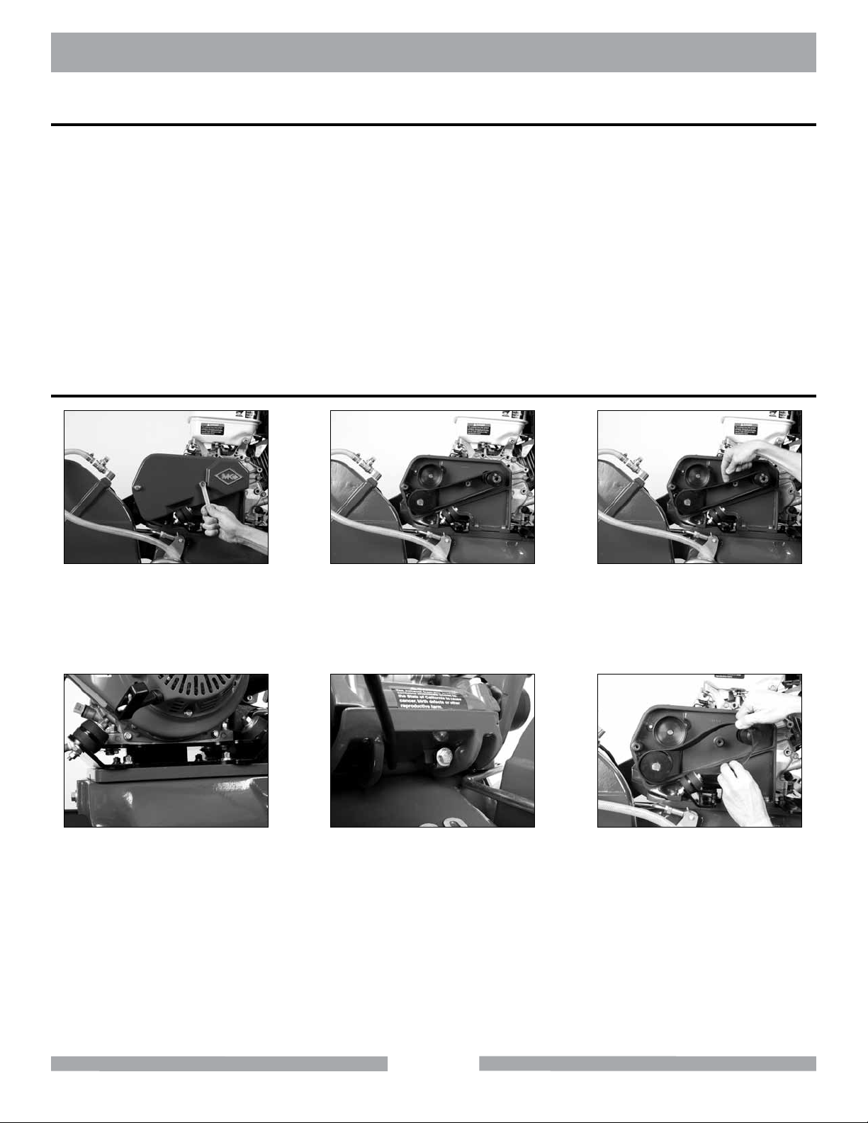
Belt Inspection, Replacement and Adjustment
The MK-5000G is designed with two belts. The two belts are a matched set and should be inspected,
adjusted and/or replaced at the same time.
NOTE:
Engine Belt
Remove the Belt Guard
Retaining Bolts.
1. When new belts are installed, they should be inspected and re-tensioned after the
rst forty-eight (48) hours of operation.
2. When performing any maintenance on the power transmission belts, always start
with the belt on the Blade Guard side.
(A)
Inspect the belt for cracks,
fraying, separation and wear.
Go to step D if replacement
(B)
required.
(C)
Check Belt for proper tension. If
tension is correct, go to step K
check tension 1/2-way between pul-
leys (proper tension 1/8" deection).
(D)
Loosen the four engine bolts
mounting plate. If re-tensioning,
go to step I.
(E)
Loosen Engine Adjustment
Strap Bolt push the Engine Mounting
Plate toward the front of the saw to
loosen the belt.
32
(F)
Remove the belt.
Page 33
MK-5000G MAINTENANCE
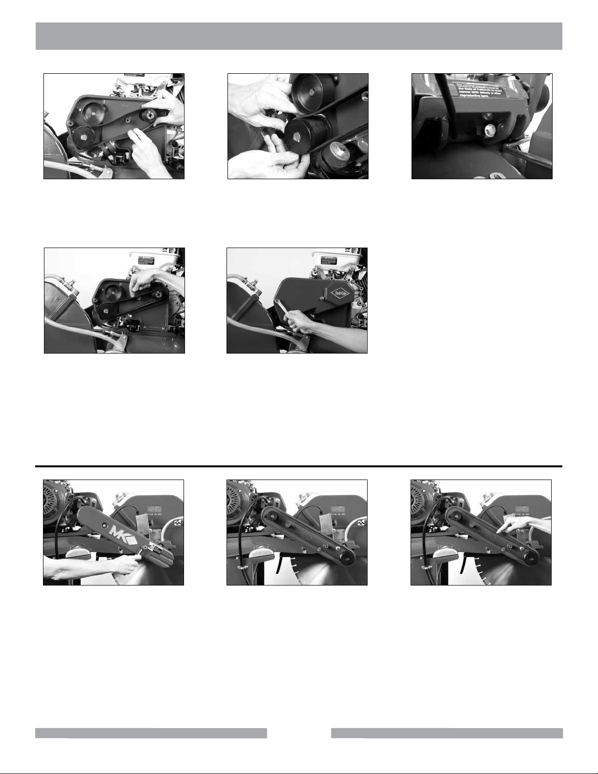
(G)
Install the new belt.
(J)
Check belt tension (proper tension
1/8" deection of the belt).
Continue adjusting belt until tension
is correct then tighten the Engine
Plate Mounting Bolts.
Blade Shaft Belt
(H)
Verify the belt is seated in the
grooves of both pulleys.
(K)
Install the Belt Guard.
(I)
Tighten the Engine Adjustment
Strap Bolt to remove slack.
(A)
Remove the Belt Guard
Retaining Bolts.
(B)
Inspect the belt for cracks, fraying,
separation and wear. Go to step D
if replacement required.
33
(C)
Check Belt for proper tension.
(proper tension 1/8-inch deec-
tion of the belt)
Page 34
MK-5000G MAINTENANCE
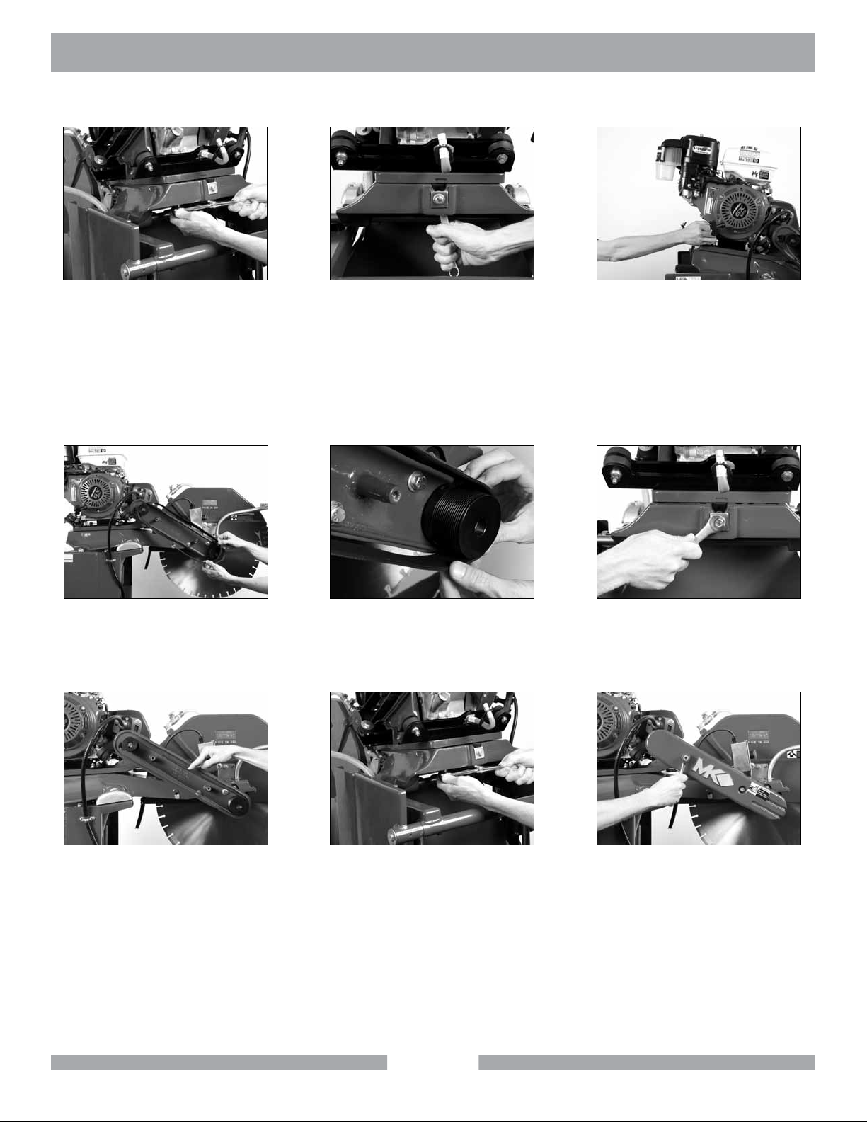
(D)
Loosen engine mounting plate
If re-tensioning, go to step J.
DO NOT use a screwdriver when installing new belts.NOTE:
(G)
Remove the belt. Install the new
belt.
(E)
Loosen Engine Adjustment
Strap Lock-nut then loosen the
Engine Adjustment Strap.
(H)
Verify the belt is seated in the
grooves of both pulleys.
(F)
Push the Engine Mounting Plate
toward the front of the unit to
loosen the belt.
(I)
Verify the Engine Adjustment
Strap Lock-nut is loose then
tighten the Adjustment Strap.
(J)
Check belt tension.
(proper tension 1/8" deection of
the belt)
(K)
Tighten Engine Mounting Plate.
34
(L)
Install the Belt Guard.
Page 35
MK-5000G TROUBLESHOOTING
MK-5000G Block Saws - Pulley Combinations by MK Part Number
Gas Saws (9-13 Hp)
Blade Size 14 inch 20 inch 24 inch
Cooling Flow Stopped
Motor Pulley 5-7-9 Hp Elect. 9-13 Hp Gas
10 Hp Elect.
Motor Pulley to Jack Shaft 160362 160362 160362
Jack Shaft to Arbor 158959 160364 160364
Arbor STD (3/4")
HD (1")
Motor Belts 160366
Arbor Belts 160367
158470
•
160362
161135
160365
•
158959
158470
160365
•
160362
161135
(A)
Check Cooling Flow
Control Valve is open.
NOTE:
“Rodding” cooling channels is performed by removing the ow control valve and then inserting a small wire rod through the cooling channel inlet, located on the underside of the Blade
Guard. The cooling channels should be “rodded” until each of the outlet ports are open and
free of foreign debris.
(D)
Verify Cooling Valve operation
by removing the valve from the
Blade Guard.
(B)
Remove Transfer Tube from
Blade Guard.
(E)
Attach the Cooling Valve to the
Transfer Tube to verify ow –
if no ow, replace valve.
(C)
Place Water Pump in clean
water source and check for ow.
(if no ow go to step G)
(F)
Locate Cooling Channels inside
Blade Guard.
35
Page 36
MK-5000G TROUBLESHOOTING
(G)
Rod Cooling Channels and
recheck ow.
Verify Water Pump suction is
clean and pump impeller is
turning. Pump Impeller is inside
(H)
water inlet.
Movable Cutting Table Does Not Move Correctly
(A)
Check for Roller Wheel Damage.
Verify ease and freedom of
(B)
Movement.
(I)
Verify Water Pump drive end is
in the operating position.
Blade Stops Turning
(A)
Check to see if engine is
running.
(B)
Check belts. (See Belt
Inspection, Adjustment and
Replacement)
36
Page 37
MK-5000G TROUBLESHOOTING
Blade Will Not Cut Properly
Check for smoothness
or “glazing”.
Engine Stops
The Engine is equipped with an oil level sensor that will stop the engine on a low oil levelNOTE:
(A)
(B)
Check for proper rotation.
(C)
Ensure Blade Core not bent.
(A)
Pull Starter Cord straight back
in a smooth fast motion.
(D)
Clean and readjust engine
Spark Plug. (See Spark Plug
Adjustment and Replacement)
(B)
Verify fuel level is below the
throat of the Fuel Tank.
37
(C)
Check for proper oil level.
(See Maintenance section if low)
Page 38
MK-5000G EXPLODED VIEW
ACCESSORIES
FRAME
38
Page 39
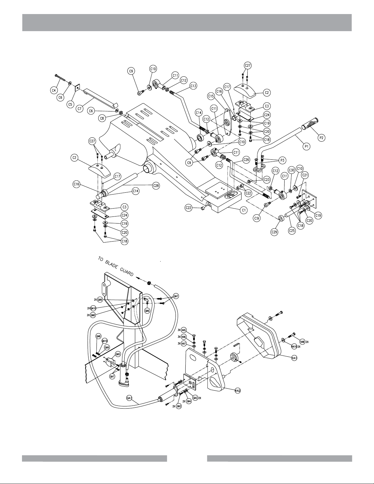
MK-5000G EXPLODED VIEW
CUTTING HEAD
39
PUMP ASSEMBLY
Page 40
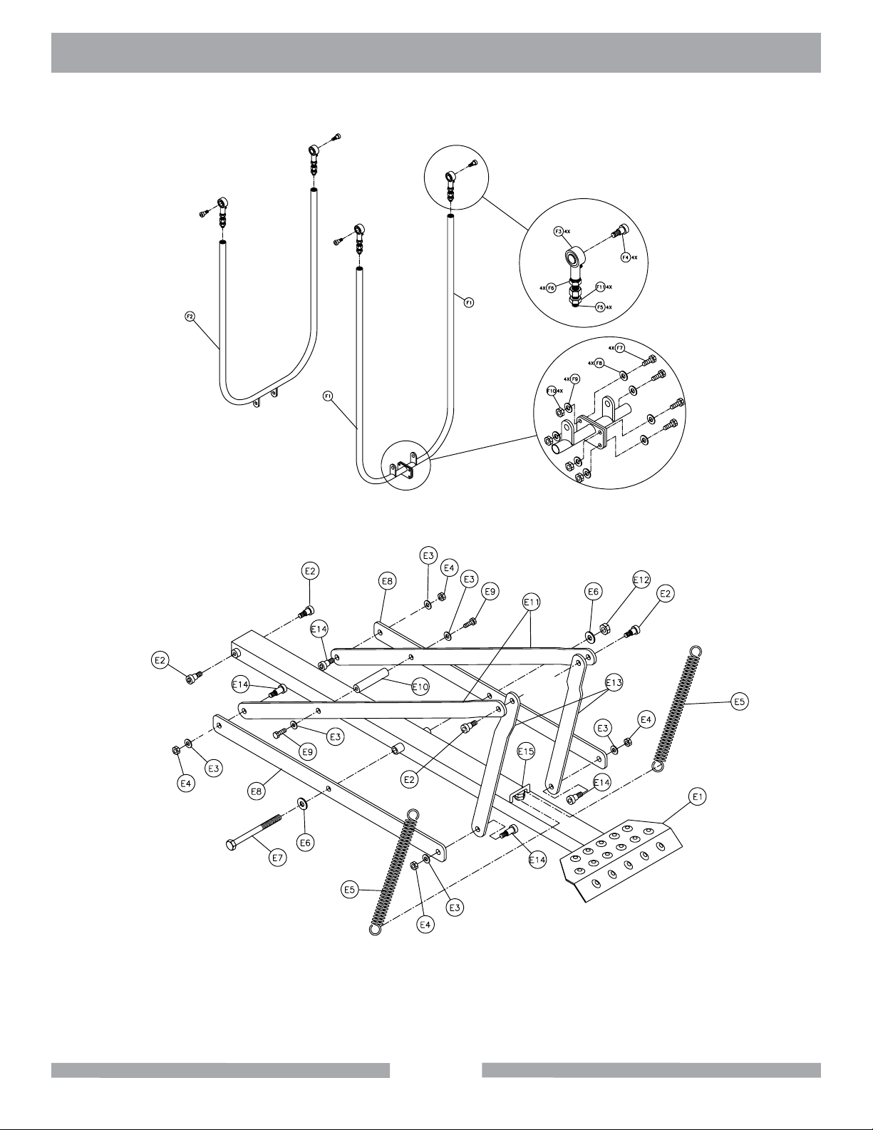
MK-5000G EXPLODED VIEW
CONNECTING LINKAGE
FOOT PEDAL LINKAGE
40
Page 41
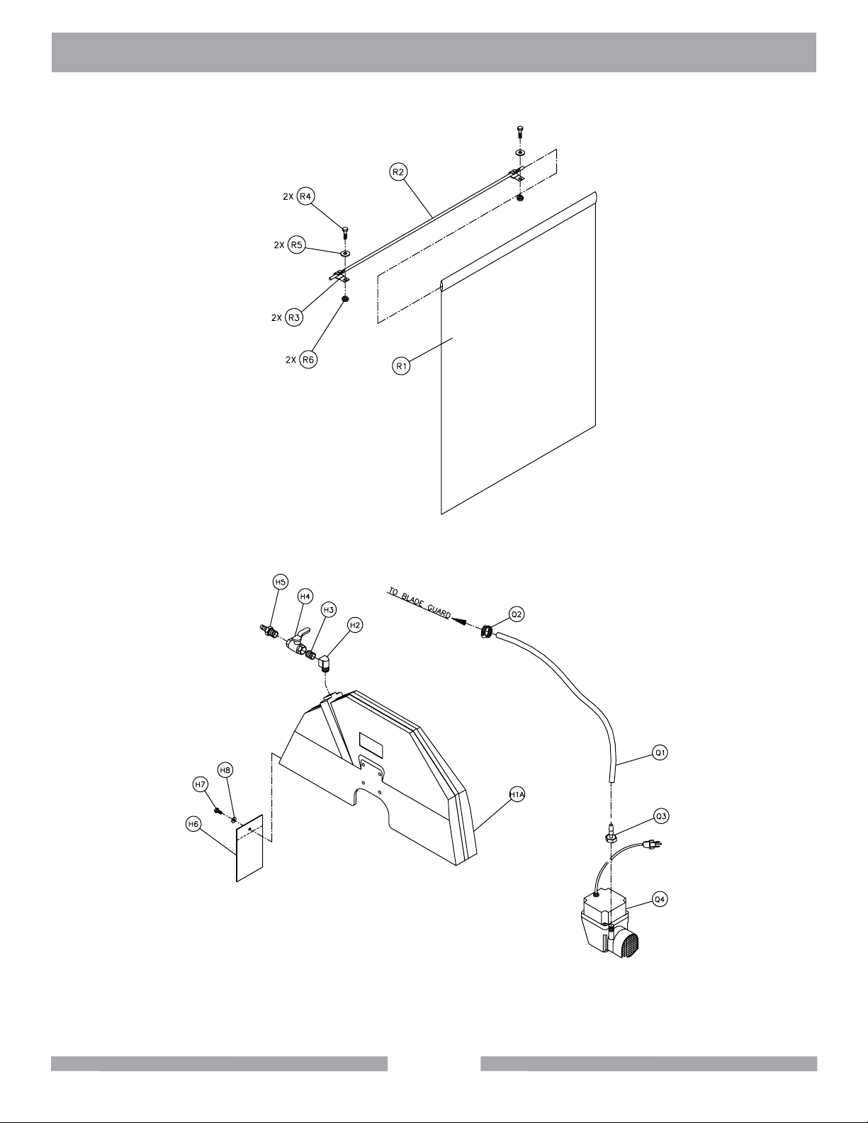
MK-5000G EXPLODED VIEW
CURTAIN
BLADE GUARD
41
Page 42
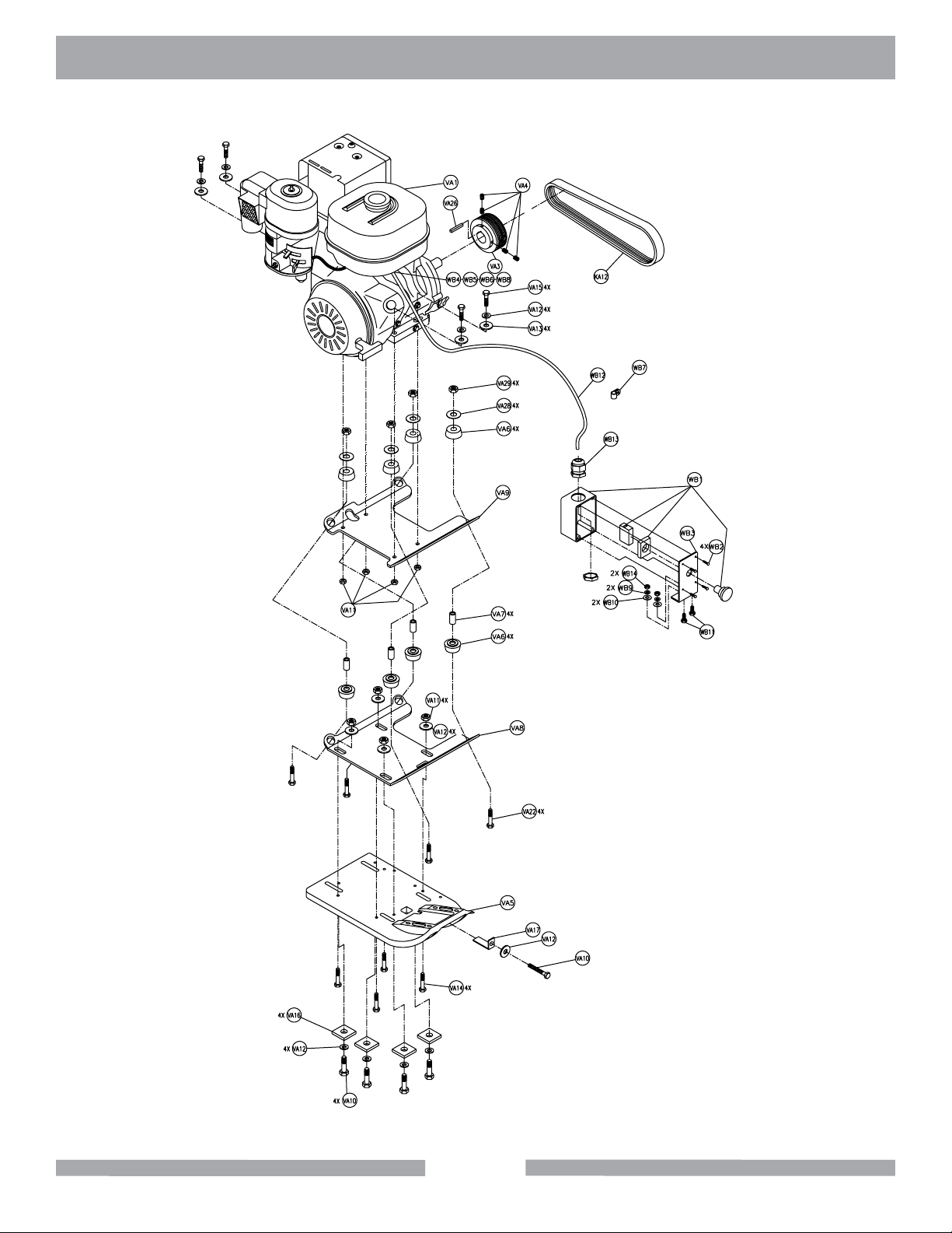
MK-5000G EXPLODED VIEW
42
ENGINE
ASSEMBLY
Page 43
MK-5000G PARTS LIST
Item Description Qty Part #
A Frames - -
A1 Frame, MK-5000 Main 1 155541
B Pivot Bracket - -
B1 Bracket, Elevation Pivot 1 156285
B2 Washer, 3/8 ID x 1-1/2 OD, Fender Washer 2 158523
B3 Screw, 1/4-20 x 1/2 Hex Head 2 152608
B4 Screw, 3/8-16 x 3/4 Hex Head 2 153527
B5 Bumper, 1/4 ID x 1-1/2 OD x 3/4 2 154496
B6 Washer, 1/4 SAE Flat 2 151915
B7 Nut, 1/4-20 Hex 2 151893
B8 Fitting, Grease (zerk) 1 153852
B9 Bushing, 1 x 1-1/4 x 2 MIS 2 154571
B10 Shaft, Pivot Arm MK-5000 1 155880
B11 Screw, 1/4-20 x 1/4 Socket Head Set, Cone point 2 153864
C Cutting Head MK-5000 - -
C1A Casting, Cutting Head (comp) 1 162545
C1B Assembly, Cutting Head, HD 1 162546
C2 Cover, 5000 Mounting Block (Comp) 2 156265
C3 Casting, 5000, Mounting Block (Comp) 2 155762
C4 Bolt, 3/8- 16 x 4-1/2 Hex Head Tap 1 153110
C5 Washer, 1-1/4 x 1-1/4 Square 1 157567
C6 Washer, 3/8 SAE Flat 2 150923
C7 Strap, Motor Adjustment 1 153611
C8 Nut, 3/8- 16 UNC 1 101188
C9 Screw, 1/2 x 1/2 Socket Head Shoulder 4 151753
C10 Washer, 1/2 SAE Flat 3 150924
C11 Joint, 1/2- 20, Female Spherical (RH) 4 154387
C12 Nut, 1/2- 20 Jam (RH) 4 154460
C13 Arm, Rear Connecting 1 158563
C14 Bearing, Ball 5/8 ID x 1-3/8 OD 2 140004
C15 Crank, Bell 1 157426
C16 Collar, Stop 5/8 ID x 1-1/8 OD x 1/2 2 140012
C17 Screw, 5/16-18 x 1/4, Socket Head Set 2 152607
C18 Screw, 5/16 x 18 x 1, Hex HD Cap 7 151743
C19 Washer, 5/16 SAE Flat 7 151754
C20 Washer, 5/16 Split Lock 7 151747
C21 Screw, 5/16-18 x 1 Flat, Socket HD Cap 1 155552
C22 Bushing, .75 x .875 x 1 Steel 3 160826
C23 Washer, Nylon .75 x 1.25 x .093 2 160827
C24 Shim, Mount Pivot Shaft Various 2 155905
C25 Shaft, Blade Guard Pivot 1 155886
C26 Link Rod, Blade Guard 1 158564
C27 Screw, 1/4- 20 x 1 Socket Head Cap 4 151049
C28 Shaft, Cutting Head Pivot 1 154828
C29 Collar, 3/4 Set 1 153814
C30 Washer, 3/8 Split Lock 1 150925
D Depth Control - -
D1 Housing, Adjustment Shaft 1 152116
D2 Screw, 3/4- 6 x 10⁻⁷/8, Depth Control 1 150840
43
Page 44
MK-5000G PARTS LIST
Item Description Qty Part #
D3 Spacer, 3/4 ID x 1 OD x 3/4 1 156249
D4 Locknut, Feed Screw 1 158227
D5 Nut, 3/8- 16 Hex Hd. 4 101188
D6 Washer, 3/8 SAE Flat 4 150923
D7 Washer, 3/8 Split Lock 4 150925
D8 Bearing, Flange FC2-25 x 3/4 ID 1 152025
D9 Spacer , .76 ID x 1 OD x 1.187 1 156250
D10 Plate, Bearing Support 1 156278
D11 Screw, 3/8-16 X 1/2 Socket Head Set, cup point 1 153710
D12 Wheel, Depth Control (comp) 1 153646
D13 Knob, Ball, 2”, 3/8-16 Insert 1 158519
D15 Screw, 1/2 x 3/4 Socket Head Shoulder 1 156177
D16 Bumper, 1-1/2 Dia. x 1/2- 13 x 3 Stud 2 158605
D17 Nut, 1/2- 13 Hex 2 151282
D18 Fitting, Grease 2 153852
DA Depth Control Lock 1 157380
DA1 Knob, Depth Lock (comp) 1 155845
DA2 Washer, Thrust 1”OD X 3/8” ID 1 155238
DA3 Lock, 5000GH Depth Control Wheel 1 157336
DA4 Bolt, Hex Head Tap, 3/8-16 x 3 1 155830
DA5 Nut, Hex, 3/8-16 1 101188
E Foot pedal Linkage - -
E1 Foot pedal and Bar, 5000 Block Saw 1 160139
E2 Screw, 1/2 x 1/2 Socket Head Shoulder 4 151753
E3 Washer, 3/8 SAE Flat 6 150923
E4 Nut, 3/8-16 Center Lock 4 153522
E5 Spring, Foot pedal 2 152115
E6 Washer, 1/2 SAE Flat 2 150924
E7 Screw, 1/2-13 x 5-1/2 Hex Head Cap 1 158526
E8 Linkage, Pedal Horizontal 2 152112
E9 Screw, 3/8- 16 x 1 Hex Head Cap 2 152507
E10 Pedal, Shaft Tie 1 156259
E11 Linkage, Pedal Diagonal 2 152113
E12 Nut, 1/2- 13 Center Lock 1 156238
E13 Linkage, Pedal Vertical 2 152114
E14 Screw, 1/2 x 3/4 Socket Head Shoulder 4 156177
E15 Hook Bolt, Weldment, 5000 Block Saw 1 160141
F Connecting Linkage
F1 Link, Front Connecting 2 156253
F2 Link, Rear Connecting 1 156252
F3 Joint, 1/2- 20 Female Spherical (RH) 4 154387
F4 Bolt, 1/2 x 1/2 Socket Head Shoulder 4 151753
F5 Screw, Adjustment 4 154433
F6 Nut, 1/2- 20 Jam 4 154460
F7 Bolt 5/16- 18 x 1 Hex HD 4 151743
F8 Washer, 5 /16 SAE Flat 4 151754
F9 Washer, 5/16 Split Lock 4 151747
F10 Nut, 5/16- 18, Hex HD 4 101196
F11 Nut, 1/2- 20 Jam (LH) 4 154461
- -
44
Page 45
MK-5000G PARTS LIST
Item Description Qty Part #
G1 Blade Shaft MK-5000 - 161308
GA1 Assembly, Blade Shaft Add Structure 1 160645
H Blade Guard MK-5000 - -
H1A
H1B
H2 Elbow, 3/8 NPT 90 Brass Street 1 152074
H3 Nipple, 3/8 NPT x Close Brass 1 152073
H4 Valve, 3/8 Ball 1 152075
H5 Fitting, 3/8 MNPT x 3/8 BARB Brass 1 152076
H6 Guard, Splash 1 160310
H7 Screw, 1/4-20 x 5/8 Hex HD 1 150404
H8 Washer, 1/4 SAE Flat 1 151915
KA Belt Guards, Gas - -
KA1 Casting, Belt Guard, Motor, Outer (comp) 1 156149
KA2 Casting, Belt Guard, Motor, Inner (comp) 1 156148
KA3 Casting, Belt Guard, Arbor, Outer (comp) 1 160888
KA4 Casting, Belt Guard, Arbor, Inner (comp) 1 160890
KA5 Screw, Hex Head 3/8-16 x 1-1/4 3 150774
KA6 Washer, Lock, Split 3/8 3 150925
KA7 Washer, Flat, SAE 3/8 3 150923
KA8 Screw, Hex Head 5/16-18 x 2-1/2 4 101675
KA9 Washer, Lock, Split 5/16 4 151747
KA10 Washer, Flat, SAE 5/16 4 151754
KA11 Screw, Hex Head 5/16 x 1-1/4 2 153950
KA12 Belt, Micro-V 16J270 1 160366
KA13 Belt, Micro-V 16J430 1 160367
Casting, Blade Guard, MK-5000 (comp) 20”
Casting, Blade Guard, MK-5000 (comp) 24”
11
159674
159324
N1 Assembly, 5000 Table 1 152124
NA1 Table Deluxe 1 165991
P Handles - -
P1A
P1B
P2 Handgrip, 7/8” 1 139949
P3 Screw, 3/8- 16 x 1 Flat Socket HD Cap 2 154019
QA Water Pump, Mechanical - -
QA1 Assembly, Pump, Water, 5000 Gas 1 152355
QA2 Screw, Hex Head Cap 3/8-16X1 2 152507
QA3 Washer, Flat SAE 3/8 2 150923
QA4 Washer, Lock, Split 3/8 2 150925
QA5 Clamp, Spring 1 152453
QA6 Clamp, Cushion Loop, 3/8 1 152592
QA7 Screw, Phil, Self Tap 10-24 x 5/8 4 153681
QA8 Nut, 10-24 4 151749
QA9 Washer, Flat, #10 SAE 4 154369
QA10 Washer, Lock, Split #10 Plated 4 153684
Handle, Cutting Head 20”
Handle, Cutting Head 24”
11
155851
155613
45
Page 46
MK-5000G PARTS LIST
Item Description Qty Part #
R Curtain - -
R1 Curtain, Splash, MK-5000 1 160764
R2 Rod, Splash Curtain 1 160711
R3 Clamp, Cushion Loop 2 152592
R4 Screw, 1/4- 20 x 3/4 Hex HD 2 152370
R5 Washer, 1/4 Flat SAE 2 151915
R6 Nut, Hex, Kep 1/4- 20 2 153941
S Accessory Pack - -
S1 Carton, Accessory Pack MK-5000 1 152432
S2 Insert, Accessory Pack MK-5000 1 152433
S3 Plug, Rubber Drain 1 153439
S4 Wrench, Masonry Saw 1 134056
S5 MK-5000G Owners Manual 1 160958
S6 Blade, MK-799DE 1 158237
T Carton - -
T1 Carton, 5000 1 152994
T2 Pallet, 5000 1 152072
VA Engines - -
VA1A
VA1B
VA2 Deector 1 155375
VA3 Pulley, 16J18X1.0 Bore 1 160365
VA4 Screw, 5/16- 18 x 3/16 Socket HD Set 12 151167
VA5 Casting, Engine Mounting (comp) 1 156140
VA6 Shock Mount, Rubber (MMC#64865K85) 8 156105
VA7 Shock Mount, Stand Off (5/8 X 3/8 TBG x 1.4) 4 156560
VA8 Mount, Engine, Lower Plate 1 158738
VA9 Mount, Engine, Upper Plate 1 158737
VA10 Screw, Hex Head 3/8-16x 1-3/4 4 150920
VA11 Nut, Hex 3/8-16 8 101188
VA12 Washer, Lock, Split 3/8 12 150925
VA13 Washer, Flat Cut 3/8 13 150923
VA14 Screw, Hex Head 3/8-16 x 1-1/4 4 150774
VA15 Screw, Hex Head Cap 3/8-16 x 2 5 153485
VA16 Washer, Square 1-1/4 x 1-1/4 4 157567
VA17 Belt Tensioner 1 160432
VA19 Pulley, 16J28X.75 Bore 1 160362
VA20 Pulley, 16J20X.75 Bore 1 160364
VA26 Key, 1/4 x 1/4 x 1-3/4 Square 1 150796
VA27 Key, 3/16 X 3/16 X 1-3/4 2 157561
VA28 Washer, Fender 5/16 ID x 1-1/2 OD 4 101527
VA29 Nut, Hex 5/16-18 4 101196
VA30 Label, Danger, California, 1.5 X 3.0 1 155581
VA31 Label, Caution, Hot Surface, 1.5 X 3.0 1 155578
VA32 Label, Danger, Lethal Exhaust, 1.5 X 3.0 1 155582
VA33 Label, Warning, Refueling, 1.5 X 3.0 1 155580
VA34 Label, Caution, Safety 1 155576
VA35 Tag, Serial Number 1 157500
Engine, 9Hp, Gasoline, Honda, Cyclone
Engine, 13Hp, Gasoline, Honda, Cyclone
11
155396
155365
46
Page 47
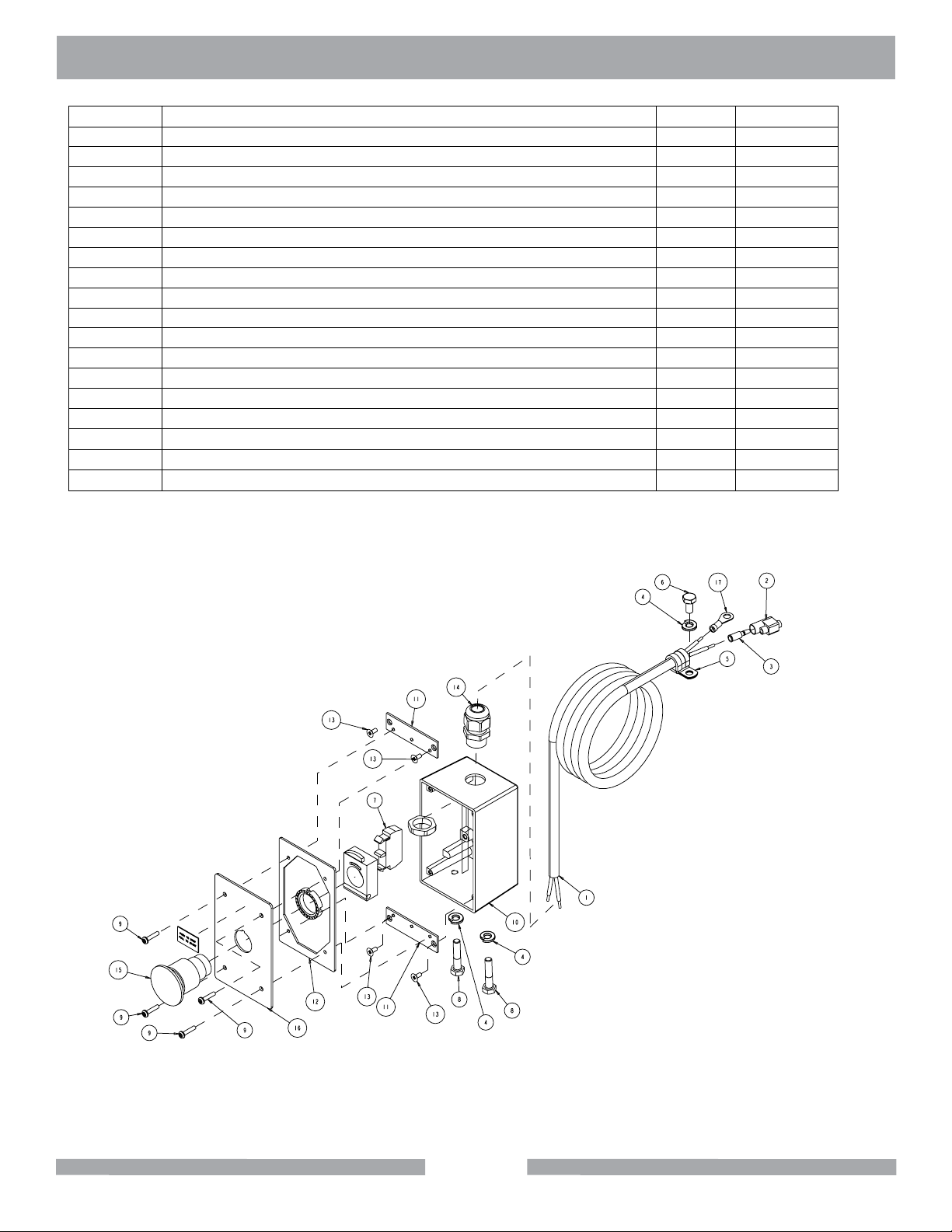
MK-5000G PARTS LIST
Item Description Qty Part #
Switch, Emergency Stop, Gasoline - 162537
1 Cord, Elec. So 16/2 1 152442
2 Connector, Bullet receptacle 1 152425
3 Terminal, Disconnect, Male 5000 1 152426
4
5
6 Screw, Hex Head 1/4-20 x 1/2 1 152608
7 Contact Block, Normally Open 1 156202
8 Screw, Hex Head 1/4-20 x 1-1/4 2 157145
9 Screw, Pan HD Phil 6-32 x 5/8 4 157393
10 Box, 30A switch (Comp) 4 157393
11 Plate, Mounting, switch 2 159489
12 Gasket, Cover, 30 Amp Switch 2 159489
13 Gasket, Cover, 30 Amp Switch 1 159491
14 Connector, Cord, Liquid Tight 1 159493
15 Assy, Switch Button, Gas 1 162080
16 Cover, Switch, Stop, Gas 1 162080
17 Terminal, 14-16 Ga x 1/4 Ring 1 162538
Washer, Lock, Split 1/4 3 152591
Clamp, Cushion Loop 3/8” 1 152592
47
SWITCH
ASSEMBLY
Page 48
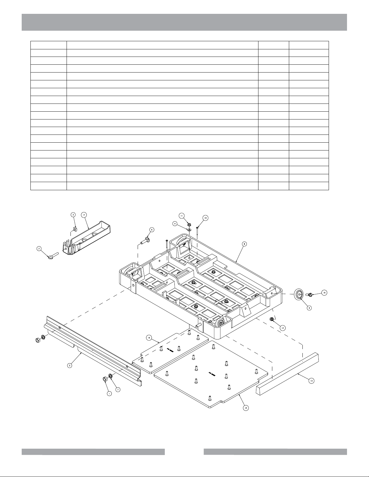
MK-5000G EXPLODED VIEW
Item Description Qty Part #
Table Assembly - 152124
1 Nut, Hex 7/16 - 14 1 150922
2 Screw, thumb 5/16 - 18 x 1 - 1/2 1 151155
3 Nut, Square 5/16 - 18 1 151156
4
5
6 Bolt, Carr. 7/16 - 14 x 1 - 1/4 2 152425
7 Washer, Lock, Split 7/16 2 152424
8 Casing, 5000, Table - Comp 1 152455
9 Wheel, Roller MK-5000, MK1080 4 152493
10 Stud, Roller Wheel 4 152494
11 Nut, Hex W/Wshr, 1/4 - 20 16 153941
12 Nut, Hex, TW, 5/16 - 18 4 153942
13 Wood Strip, Table Insert 1 157748
14 Screw, #8 x 1 - 1/2 Flat HD Phil 2 158157
15 Mat, MK-5000 Table-Lg 1 160165
16 Mat, MK-5000 Table - SM 1 160166
17 Casing, Squaring Arm-Comp 1 231276
Washer, 1/4 Sae Flat 16 151915
Rule, Front Stop 1 152126
48
TABLE
ASSEMBLY
Page 49
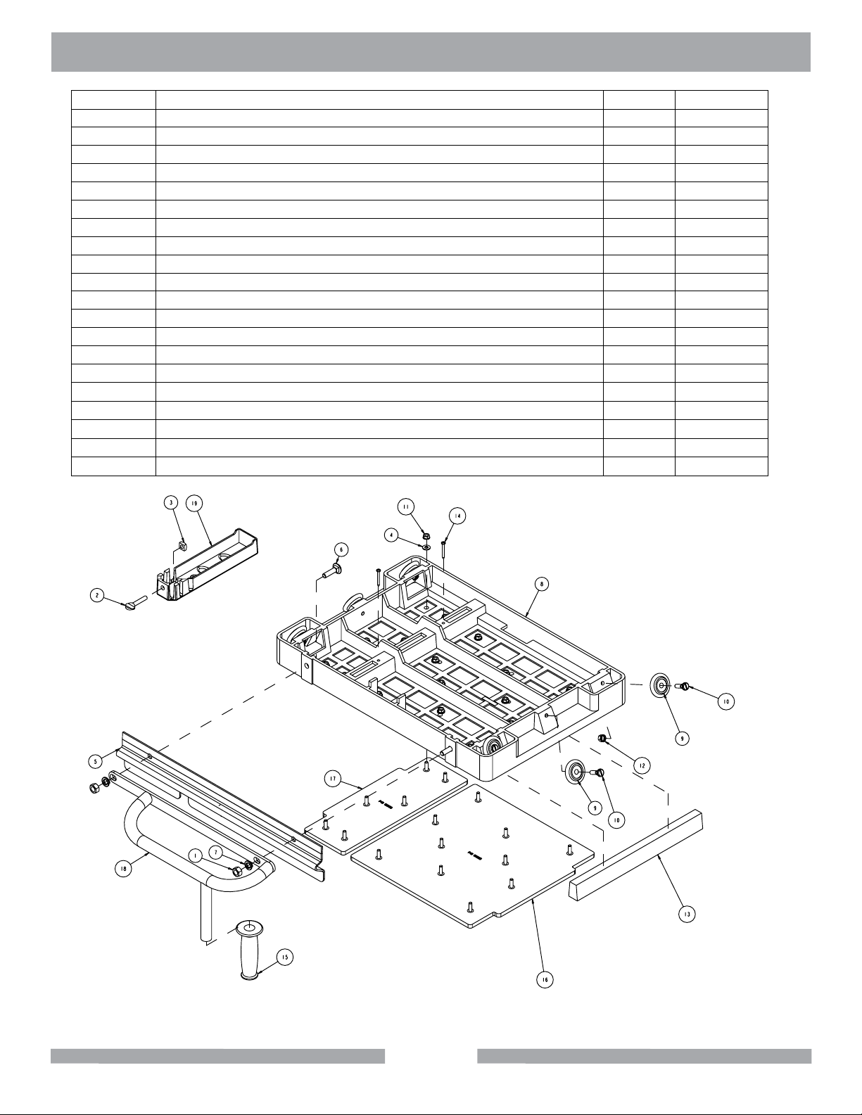
MK-5000G EXPLODED VIEW
Item Description Qty Part #
Table Assembly Deluxe - 165991
1 Nut, Hex 7/16 - 14 1 150922
2 Screw, thumb 5/16 - 18 x 1 - 1/2 1 151155
3 Nut, Square 5/16 - 18 1 151156
4
5
6 Bolt, Carr. 7/16 - 14 x 1 - 1/4 2 152425
7 Washer, Lock, Split 7/16 2 152424
8 Casing, 5000, Table - Comp 1 152455
9 Wheel, Roller MK-5000, MK1080 4 152455
10 Stud, Roller Wheel 4 152494
11 Nut, Hex W/Wshr, 1/4 - 20 16 153941
12 Nut, Hex, TW, 5/16 - 18 4 153942
13 Wood Strip, Table Insert 1 157748
14 Screw, #8 x 1 - 1/2 Flat HD Phil 2 158157
15 Grip, Handle 7/8 ID 1 158608
16 Mat, MK-5000 Table-LG 1 160165
17 Mat, MK-5000 Table - SM 1 160166
18 Handle, Table 1 165990-L
19 Casing, Squaring Arm-Comp 1 231276
Washer, 1/4 Sae Flat 16 151915
Rule, Front Stop 1 152126
49
DELUXE
TABLE
ASSEMBLY
Page 50
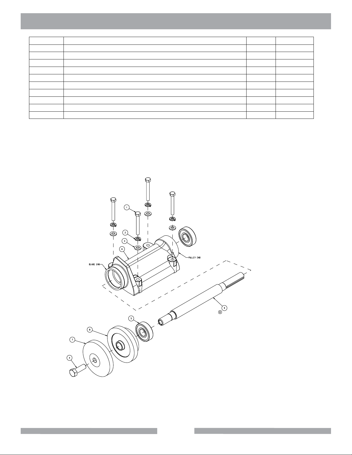
MK-5000G EXPLODED VIEW
Item Description Qty Part #
Arbor Assembly Standard - 161208
1 Screw, Hex HD 5/16 - 18 x 2 - 1/2 4 101675
2 Washer, 5/16 Split Lock 4 151747
3 Washer, 5/16 Sae Flat 4 151754
4
5
6 Casting, 2000/5000 Arbor - Comp 1 154637
7 Flange, Outer, Masonry, 4" 1 161304
8 Flange, Outer, Masonry, 4" 1 161305
9 Shaft, Blade, 20mm 1 165861
Screw, Hex HD 1/2 - 20 x 1-1/4 1 152122
Bearing, Arbor Housing 2 154594
50
BLADE SHAFT
ASSEMBLY
(STANDARD)
Page 51
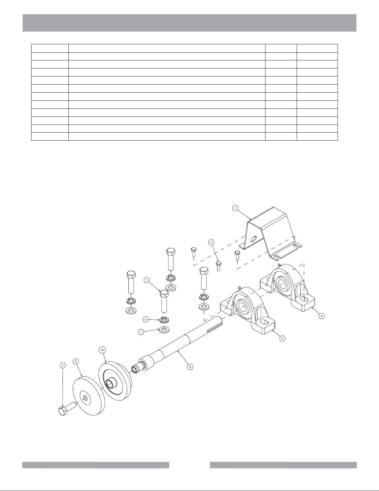
MK-5000G EXPLODED VIEW
Item Description Qty Part #
Blade Shaft Assembly Heavy Duty - 160645
1 Washer,1/2 Saw Flat 4 150924
2 Screw, Hex HD 1/2 - 20 x 1 - 1.4 1 152122
3 Washer, 1/2 Split Lock 4 153524
4
5
6 Bearing, 1.0 ID Pillow Block 2 157924
7 Guard, Shaft 5000D 1 160398
8 Shaft, Blade, Heavy Duty 1 161137
9 Flange, Outer, Masonry, 4" 1 161304
10 Flange, Inner Masonry, 4" 1 161305
Screw, Hex HD 1/4 - 20 x 3/8 3 153526
Screw, Hex HD 1/2 - 13 x 2 4 153533
51
BLADE SHAFT
ASSEMBLY
(HEAVY DUTY)
Page 52
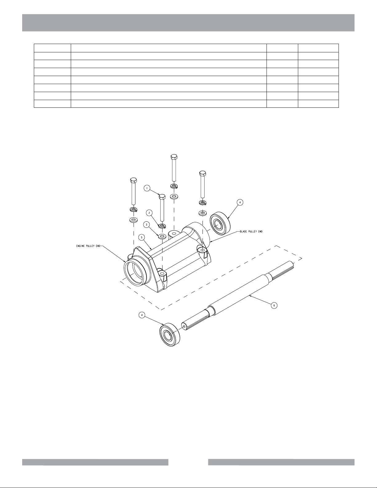
MK-5000G EXPLODED VIEW
Item Description Qty Part #
Jackshaft Assembly - 166045
1 Screw, Hex HD 5/16 - 18 x 2 - 1/2 4 101675
2 Washer, 5/16 Split Lock 4 151747
3 Washer, 5/16 Sae Flat 4 151754
4
5 Casting, 2000/5000 Arbor - Comp 1 154637
6 Shaft, Jack 1 156117
Bearing, Arbor Housing 2 154594
52
JACKSHAFT
ASSEMBLY
Page 53
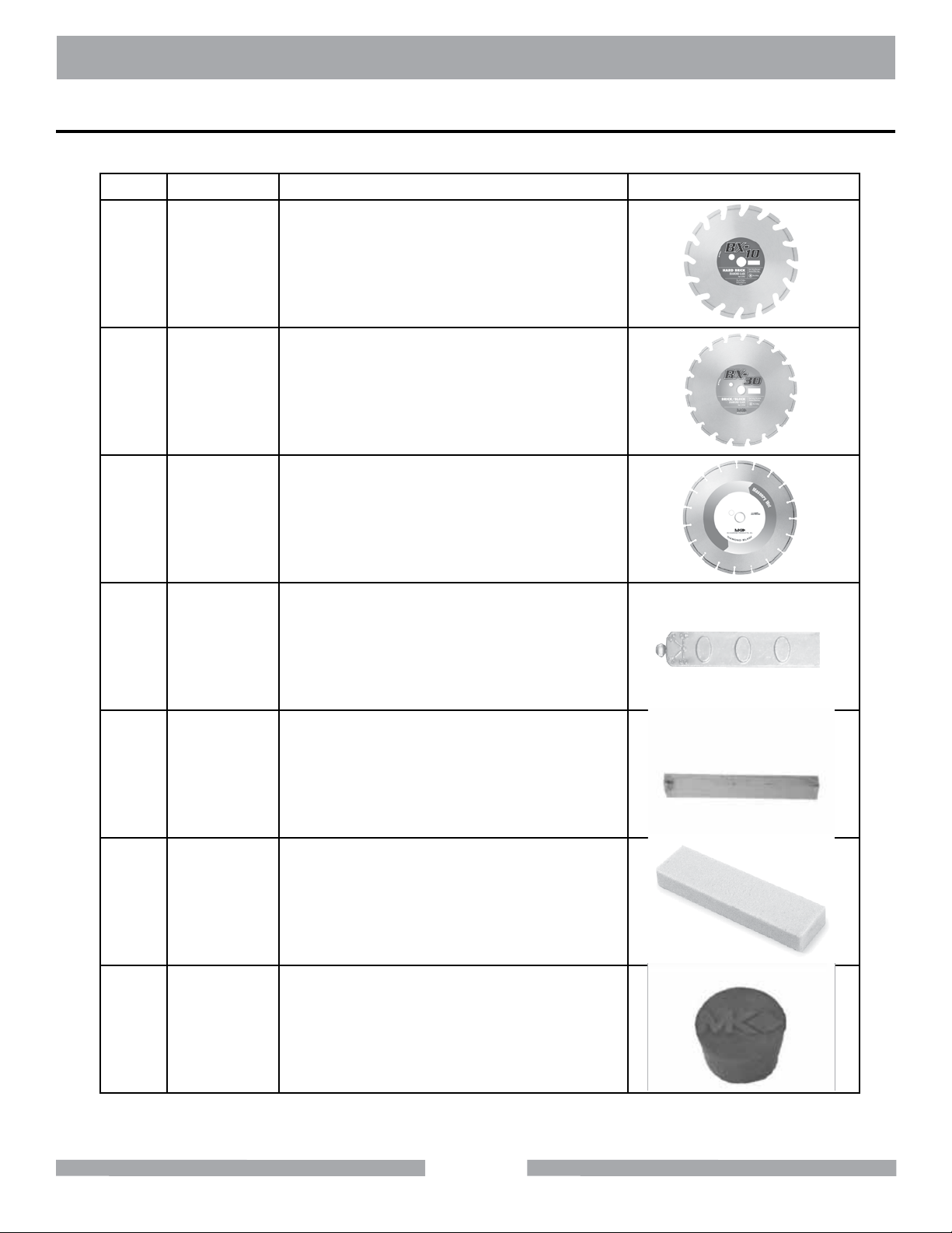
MK-5000G ACCESSORIES
ACCESSORIES
Item Number
1. 157957
2. 157944
3. 128678
Description
BX-10
14" Premium Grade Diamond Blades for
Dry Cutting of Hard Brick
BX-30
14" Premium Grade Diamond Blades for
Dry Cutting of Hard Brick
MK-30
20" Supreme Grade Blades for Brick &
Block
4. 132332 Adjustable Cutting Guide
5. 156427 Protective Wooden Strip
6. 152792 Dressing Stick
7. 153439 Rubber Drain Plug
53
Page 54

MK-5000G
ORDERING AND RETURN INFORMATION
ORDERING INFORMATION
You may order MK Diamond products through your local MK Diamond distributor or, you may order
direct from MK Diamond.
When ordering direct from MK Diamond, please have the following information ready before calling:
• The Model Number of the saw
• The Serial Number of the saw
• Where the saw was purchased and when
• The Part Number for the part(s) being ordered
• The Part Description for the part(s) being ordered
NOTE: There is a $25.00 minimum order when ordering direct from MK Diamond. A $5.00 charge will
be added to orders having a net billing value under $50.00. All purchases must be made using VISA,
MasterCard or American Express.
All parts may be ordered by calling toll free to – 800 421-5830 or 310 539-5221 and asking for
Customer Service. For technical questions, call – 800 474-5594.
RETURN MATERIALS POLICY
To expedite the service relative to the return of a product purchased through MK Diamond, please
observe the following:
NOTE: When returning all items, they must have been purchased within the previous twelve (12)
months.
• Have the Model Number of the saw
• Have the Serial Number of the saw
• Have the location of where the saw was purchased
• Have the date when the saw was purchased
• Contact Customer Service for approval to return the item(s)
• Obtain a Returned Goods Number (RGA) authorizing the return
• Follow the packaging instructions in the following section
• Ensure your item(s) are prepaid to the destination
For returned items, call toll free to – 800 421-5830 or 310 539-5221 and ask for Customer Service.
For technical questions, call – 800 474-5594 or 310 257-2845.
PACKAGING INSTRUCTIONS
• Remove the Cutting Head and Support Angle Assembly
• Dry the saw before shipping
• When packing, include the following: Saw, Diamond Blade, Blade Guard and Support Angle
Assembly and Adjustable Cutting Guide (Other Accessories are not required)
• Package the unit in its original container or one of comparable size (do not ship the unit partially
exposed)
• Ensure all parts are secured in the packaging to prevent moving
AUTHORIZED SERVICE CENTERS
For quicker repair time, you may contact MK Diamond Customer Service, toll free, at 800 421-5830
or 310 539-5221 for the Authorized Service Center closest too you or visit our web site at
www.mkdiamond.com. For technical questions, call – 800 474-5594.
54
Page 55

CONTACT AND LIMITED WARRANTY
MK-5000G
CONTACT:
Please contact MK Diamond Products, Inc. Customer Service Department with any questions you
might have regarding distributors, parts or service.
Telephone: (800) 421-5830
Fax: (310) 539-5158
E-mail: [email protected]
Customer Service Hours: Monday through Friday, 6AM-4PM PST
MK Diamond Products, Inc.
1315 Storm Parkway
Torrance, CA 90501
MK DIAMOND PRODUCTS, INC. LIMITED WARRANTY
MK DIAMOND PRODUCTS, INC. will guarantee every machine they build, to be free from defects in
material and workmanship for (1) one year from date of purchase. The obligation of MK DIAMOND
PRODUCTS, INC. under this warranty is limited to the repair or replacement of any parts which,
under normal use, prove to be defective in material or workmanship. The parts involved or the unit
in question should be returned to MK DIAMOND PRODUCTS, INC. or to a point designated by us,
transportation prepaid.
This warranty does not obligate us to bear the cost of labor or transportation charges in connection
with replacement or repair of defective parts. Likewise, it shall NOT apply to any unit which has been
subjected to misuse, neglect or accident. This warranty does NOT apply to any machine which has
been repaired or altered outside our factory.
This warranty does NOT obligate MK DIAMOND PRODUCTS, INC., with respect to items not of our
manufacture, such as engines, motors, hydraulics, etc., which are subject to their own guarantees and
warranties.
We shall in no event be liable for consequential damages or contingent liabilities arising out of failure
of any equipment or parts to operate properly.
© COPYRIGHT 2012, MK DIAMOND PRODUCTS, INC. ALL RIGHTS RESERVED.
The MK Diamond logo is a registered trademark of MK Diamond Products, Inc. and may not be used,
reproduced, or altered without written permission. All other trademarks are the property of their respective owners and used with permission.
MK Diamond may have patents, patent applications, trade marks, copyrights of other intellectual
property right covering this product in this document.
This manual MUST accompany the equipment at all times. This manual is considered a permanent
part of the equipment and should remain with the unit if resold.
The information and specications included in this publication were in effect at the time of approval for
printing.
55
Page 56
MK-5000G Block Saw
OWNERS MANUAL & OPERATING INSTRUCTIONS
MK Diamond Products, Inc.
1315 Storm Parkway
Torrance, CA 90501
Toll-Free: (800) 421-5830
Phone: (310) 539-5221
Fax: (310) 539-5158
www.mkdiamond.com
 Loading...