

Page 1

www.mkdiamond.com
MK-1503SS
OWNER'S MANUAL
OPERATING INSTRUCTIONS
Revision 101
Manual Part# 169263
Caution: Read all safety and operating instructions
before using this equipment. This parts list MUST
accompany the equipment at all times.
06.2011
Page 2

INTRODUCTION
Congratulations on your purchase of a MK-1503SS Wet Stone Polisher. We are certain that you will
be pleased with your purchase. MK Diamond takes pride in producing the nest construction power
tools and diamond blades in the industry.
Operated correctly, your MK-1503SS should provide you with years of service. In order to help you,
we have included this manual. This owners manual contains information necessary to operate and
maintain your MK-1503SS safely and correctly. Please take the time to familiarize yourself with the
MK-1503SS by reading and reviewing this manual.
Read and follow all safety, operating and maintenance instructions.
If you should have questions concerning your Grinder, please feel free to call our friendly customer
service department at: 800 421-5830
Regards,
MK Diamond
NOTE THIS INFORMATION FOR FUTURE USE:
MODEL NUMBER:
SERIAL NUMBER:
PURCHASE PLACE:
PURCHASE DATE:
NOTE: For your (1) one year warranty to be effective, complete the warranty card
(including the Serial Number) and mail it in as soon as possible.
2
Page 3

TABLE OF CONTENTS
SAFETY
Safety Messages 4
Damage Prevention Message 4
General Safety Precautions 6
California Proposition 65 Message 6
Hazard Symbols 7
Electrical Requirement and Grounding Instruction 8-10
Product Specications 11
UNPACKING, TRANSPORT and ASSEMBLY
Unpacking 12
Contents 12
Assembly 13
SETUP, OPERATION and CLEANUP
Setup 14-15
Operation 16
Cleanup 17
MAINTENANCE AND TROUBLESHOOTING
Maintenance 17-19
THEORY
Theory Of Polishing Pads 20
ACCESSORIES ORDERING and RETURN INSTRUCTIONS
Accessories 21
Replacement Parts 22
Ordering Information 23
Return Material Policy 23
Packaging Instructions 23
Authorized Service Centers 23
3
Page 4
MK-1503SS SAFETY
Read and follow all safety, operating and maintenance instructions. Failure to read and follow
these instructions could result in injury or death to you or others. Failure to read and follow these
instructions could also result in damage and/or reduced equipment life.
SAFETY MESSAGES
A safety message alerts you to potential hazards that could hurt you or others. Each safety message is preceded by a safety alert symbol ( ) and one of three words: DANGER, WARNING, or CAUTION.
DANGER
WARNING
CAUTION
You WILL be KILLED or SERIOUSLY INJURED if you do not follow directions.
You CAN be KILLED or SERIOUSLY INJURED if you do not follow directions.
You CAN be INJURED if you do not follow directions. It may also be used to alert
against unsafe practices.
DAMAGE PREVENTION AND INFORMATION MESSAGES:
A Damage Prevention Message is to inform the user of important information and/or instructions that
could lead to equipment or other property damage if not followed. Information Messages convey
information that pertains to the equipment being used. Each message will be preceded by the word
NOTE, as in the example below.
NOTE:
Equipment and/or property damage may result if these instructions are not followed.
GENERAL SAFETY PRECAUTIONS AND HAZARD SYMBOLS
In order to prevent injury, the following safety precautions and symbols should be followed at all times!
SAFETY PRECAUTIONS
ALWAYS read this Owner’s Manual before operating the machine.
ALWAYS keep the Guards in place.
REMOVE ADJUSTING KEYS AND WRENCHES
Form a habit of checking to see that keys and adjusting wrenches are removed from
the power tool before it is turned on.
KEEP WORK AREA CLEAN
Cluttered work areas and benches invite accidents.
DO NOT USE IN DANGEROUS PLACES
DO NOT use power tools in damp or wet locations nor expose them to rain. Always
keep the work area well lighted.
KEEP CHILDREN AWAY
All visitors and children should be kept a safe distance from work area.
4
Page 5
MK-1503SS SAFETY
MAKE THE WORKSHOP KID PROOF
Make the workshops kid proof by using padlocks, master switches or by removing starter
keys.
DO NOT FORCE THE TOOL
A power tool will do a job better and safer operating at the rate for which it was designed.
USE THE RIGHT TOOL
DO NOT force a tool or an attachment, to do a job that it was not designed to do.
USE THE PROPER EXTENSION CORD
If using an extension cord make sure it is in good condition first. When using an extension
cord, be sure to use one heavy enough to carry the current your product will draw. An
undersized cord will cause a drop in line voltage that will result in a loss of power and
overheating. TABLE 1, Page 10 shows the correct AWG size to use depending on cord
length and nameplate ampere rating. If in doubt, use the next heavier gage. The smaller
the gage number, the heavier the cord.
USE PROPER APPAREL
DO NOT wear loose clothing, gloves, neckties, rings, bracelets, or other jewelry that may
be caught in moving parts. Non-slip footwear is recommended. Wear protective hair
covering to contain long hair.
ALWAYS wear approved eye protection.
ALWAYS wear approved respiratory protection.
SECURE WORK
Clamps or a vise should be used to hold work whenever practical. Keeping your
hands free to operate a power tool is safer.
DO NOT OVERREACH
Keep proper footing and balance at all times by not overreaching.
MAINTAIN TOOLS WITH CARE
Keep tools clean for the best and safest performance. Always follow maintenance
instructions for lubricating, and when changing accessories.
ON / OFF
DISCONNECT TOOLS
Power tools should always be disconnected before servicing or when changing
accessories, such as blades, bits, cutters, and the like.
ALWAYS place the power ON/OFF switch in the OFF position when the tool is not in use.
5
Page 6

MK-1503SS SAFETY
USE RECOMMENDED ACCESSORIES
Consult the owner’s manual for recommended accessories. Using improper accessories
may increase the risk of personal or by-stander injury.
NEVER STAND ON THE TOOL
Serious injury could occur if a power tool is tipped, or if a cutting tool is unintentionally
contacted.
CHECK FOR DAMAGED PARTS
Before using a power tool, check for damaged part. A guard or any other part that is
damaged should be carefully checked to determine if would operate properly and perform
its intended function. Always check moving parts for proper alignment or binding. Check
for broken parts and mountings and all other conditions that may affect the operation of
the power tool. A guard, or any damaged part, should be properly repaired or replaced.
DIRECTION OF FEED
ALWAYS feed work into a blade or cutter against the direction of rotation. A blade
or cutter should always be installed such that rotation is in the direction of the arrow
imprinted on the side of the blade or cutter.
NEVER LEAVE A TOOL UNATTENDED
TURN POWER OFF - Do not leave a tool until it comes to a complete stop. Always
turn a power tool OFF when leaving the work area, or, when a cut is finished.
CALIFORNIA PROPOSITION 65 MESSAGE
WARNING
Some dust created by power sanding, polishing, grinding, drilling, and other construction activities
contain chemicals known (to the State of California) to cause cancer, birth defects or other reproductive harm. Some examples of these chemicals are:
• Lead, from lead-based paints
• Crystalline silica, from bricks and cement and other masonry products
• Arsenic and chromium, from chemically treated lumber
For further information, consult the following sources:
http://www.osha.gov/SLTC/silicacrystalline/index.html
http://www.cdc.gov/niosh/consilic.html
http://oehha.ca.gov/prop65/law/P65law72003.html
http://www.dir.ca.gov/Title8/sub4.html
Your risk from these exposures varies depending on how often you do this type of work. To reduce
your exposure to these chemicals, work in a well-ventilated area, and work with approved safety
equipment, such as those dust masks that are specially designed to lter out microscopic particles.
6
Page 7
(
(
)
)
MK-1503SS SAFETY
HAZARD SYMBOLS
ELECTRICAL SHOCK
NEVER touch electrical wires or components while the engine is running. They can be
sources of electrical shock which could cause severe injury or burns.
ROTATING PARTS
Keep hands, feet, hair, and clothing away from all moving parts to prevent injury.
Never operate the motor with covers, shrouds, or guards removed.
OVER SPEED
NEVER tamper with the governor components or settings to increase the maximum
speed. Severe personal injury and damage to the engine or equipment can result if
operated at speeds above maximum.
DO NOT EXPOSE TO RAIN
DO NOT expose to rain or use in damp locations.
WARNING
Polishing and drilling generates dust. Excessive airborne particles may cause irritation to eyes, skin
and respiratory tract. To avoid breathing impairment, always employ dust controls and protection
suitable to the material being polished or drilled; See OSHA (29 CFR Part 1910.1200). Diamond
Blades improperly used are dangerous. Comply with American National Standards Institute Safety
Code, B7.1 and, Occupational Safety and Health Act covering Speed, Safety Guards, Flanges,
Mounting Procedures, General Operating Rules, Handling, Storage and General Machine Conditions
7
Page 8
MK-1503SS SAFETY
ELECTRICAL REQUIREMENTS AND GROUNDING INSTRUCTIONS
In order to prevent potential electrical shock and injury, the following electrical safety precautions and
symbols should be followed at all times!
WARNING
In case of a malfunction or breakdown, grounding provides a path of least resistance for electric current to reduce the risk of electric shock. This tool is equipped with an electric cord having an equipment-grounding conductor and a grounding plug. The plug must be plugged into a matching outlet
that is properly installed and grounded in accordance with all local codes and ordinances.
• Do not modify the plug provided – if it will not t the outlet; have the proper outlet installed by a
qualied electrician
• Improper connections of the equipment-grounding conductor can result in a risk of electric
shock. The equipment-grounding conductor is the insulated conductor that has an outer surface
that is green, with or without yellow stripes. If repair or replacement of the electric cord or plug is
necessary, do not connect the equipment-grounding conductor to a live terminal
• Check with a qualied electrician or service personnel if the grounding instructions are not
completely understood, or if in doubt as to whether the tool is properly grounded
• Use only 3-wire extension cords that have 3-prong grounding plugs and 3-pole receptacles that
accept the tool’s plug
• Repair or replace a damaged or worn cord immediately
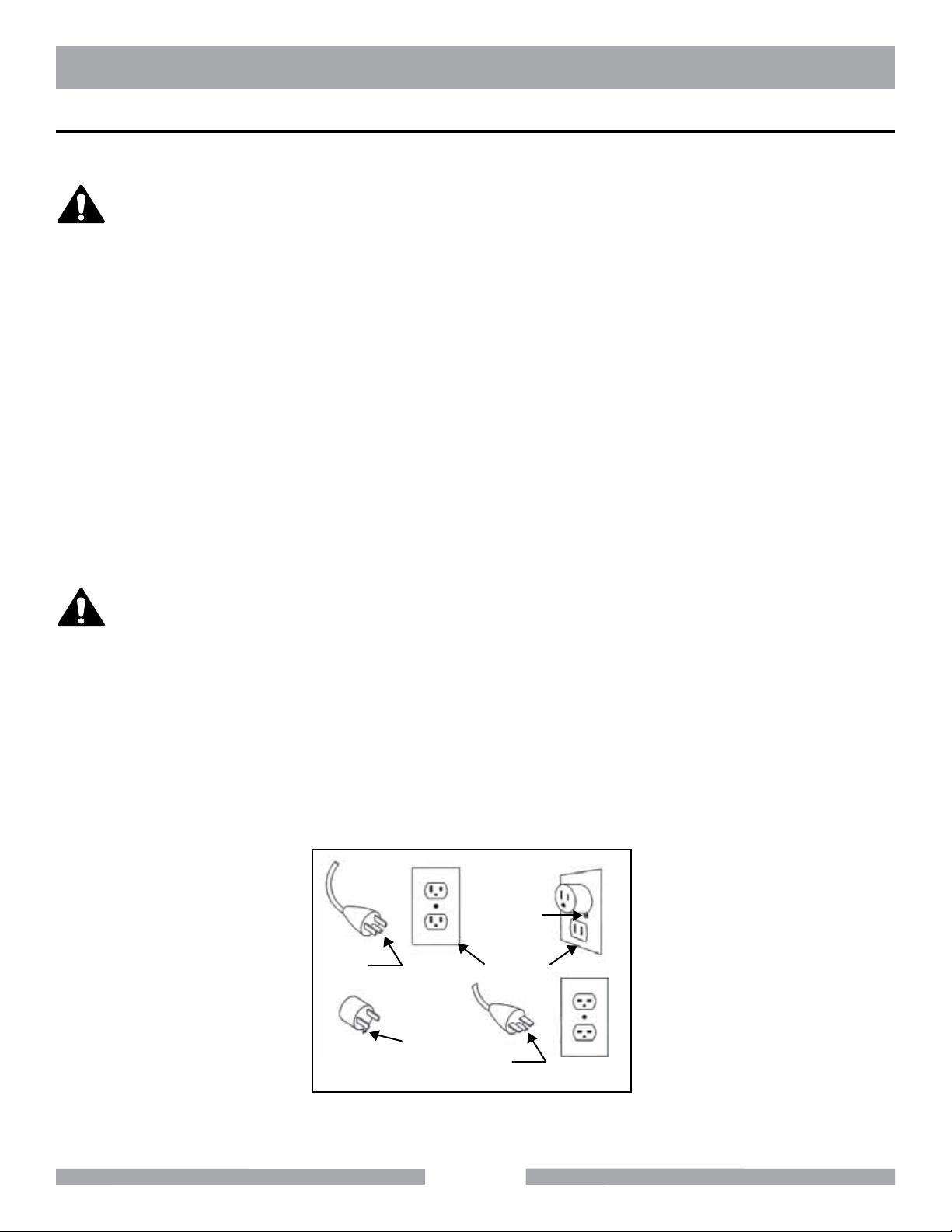
WARNING
This tool is intended for use on a circuit that has an outlet that looks like the one shown in Sketch A.
The tool has a grounding plug that looks like the plug illustrated in Sketch A. A temporary adapter,
which looks like the adapter illustrated in sketches B and C, may be used to connect this plug to a
2-pole receptacle as shown in Sketch B, if a properly grounded outlet is not available. The temporary
adapter should be used only until a properly grounded outlet can be installed by a qualied electrician. The green-colored rigid ear, lug, and the like, extending from the adapter, must be connected to
a permanent ground such as a properly grounded outlet box.
NOTE: Use of a temporary adapter is not permitted in Canada.
Metal Screw
Grounding
Pin
(A)
ADAPTER
Grounding
Means
(C)
Cover of
Grounded
Outlet Box
Grounding
Pin
(B)
(D)
Circuit and Adapter Information
8
Page 9

MK-1503SS SAFETY
WARNING
The polisher requires a Ground Fault Circuit Interrupter (GFCI). To reduce the risk of electrocution,
keep all connections dry and off the ground. A GFCI is provided as an integral part of the power cord
for the tool. Receptacles are available having built-in GFCI protectors and may be used with this
equipment. When using an extension cord, the GFCI in the power cord and extension cord connections need to be kept dry and off the ground.
WARNING
To avoid the possibility of the in-line GFCI getting wet, position it to the side of the work area. A “drip
loop” shown in the picture below, should be arranged by the user to properly protect the GFCI.
The “drip loop” is that part of the cord below the level of the GFCI or the connector, if an extension
cord is used. This method of positioning the cord prevents water traveling along the power cord, coming in contact with the GFCI, extension cord connections or receptacle.
If the GFCI, plug or receptacle get wet, DO NOT unplug the cord. Disconnect the fuse or circuit
breaker that supplies power to the tool. Then unplug and examine all components for presence of
water.
NOTE:
Drip Loop Information - Raise GFCI and plug off the oor with a cardboard carton
or brick or other non-conductive support to prevent water from traveling along the
power cord.
Extension Cord
Drip Loops
Drip Loop Information
GFCI Tool
9
Page 10

MK-1503SS SAFETY
WARNING
Use only extensions cords that are intended for outdoor use. These extension cords are identied
by a marking “Acceptable for use with outdoor appliances; store indoors while not in use.” Use only
extension cords having an electrical rating not less than the rating of the product. Do not use damaged extension cords. Examine extension cords before using and replace if damaged. Do not abuse
extension cords and do not yank on any cord to disconnect. Keep cords away from heat and sharp
edges. Always disconnect the extension cord from the receptacle before disconnection the product
form the extension cord.
WARNING
To reduce the risk of electrocution, keep all connections dry and off the ground. Do not touch the
plug with wet hands.
WARNING
Use of undersize extension cords result in low voltage to the motor that can result in motor burnout
and premature failure. MK Diamond warns that equipment returned to us showing signs of being run
in a low voltage condition, through the use of undersized extension cords will be repaired or replaced
totally at the customers expense. There will be no warranty claim.
To choose the proper extension cord,
• Locate the length of extension cord needed in table provided.
• Once the proper length is found, move down the column to obtain the correct AWG size
required for that length of extension cord. For example, a fty foot extension cord would require
an AWG size of 14 for a 230V volt circuit.
EXTENSION CORD MINIMUM GAGE FOR LENGTH
VOLTS TOTAL LENGTH OF CORD IN FEET
25 ft.
AWG
115V 14 12 Not Recommended Not Recommended
230V 14 14 12 N/A
50 ft.
AWG
Table 1
100 ft.
AWG
150 ft.
AWG
10
Page 11

MK-1503SS SAFETY
PRODUCT SPECIFICATIONS
The MK-1503SS is a versatile Wet Stone Polisher. Operated and used according to this manual, the
MK-1503SS
will provide years of dependable service.
General Description
The MK-1503SS Wet Stone Polisher is engineered as a handheld Wet Stone Polisher. The polisher
is designed with a powerful 120V motor in a rugged plastic housing. MK-1503SS Part# 167556, MK1503SS Kit Part # 157493-MK
MotorSpecications
Motor specications for the MK-1503SS are listed in the table below.
Voltage 120V
Amperage 7.9
Frequency 50/60 Hz
RPM 3200 rpm
Weight 6 lbs.
Polishing Pad Capacity
The MK-1503SS uses a three (3), four (4), or ve (5) inch (76, 102, or 127 mm) diameter, wet polishing pad.
Tile Types
The MK-1503SS can polish all variety of tile types including Porcelain, Terracotta, Marble, Quarry and
Slate, or almost any other non-ferrous material
Replaceable Motor Brushes
The MK-1503SS is equipped with replaceable motor brushes to extend operating life.
SerialNumberandProductSpecicationLabelLocation
The Serial Number and Product Specication Label is located on the right side of the MK-1503SS as
shown.
11
Page 12

MK-1503SS UNPACKING
UNPACKING
Your MK-1503SS Wet Stone Polisher has been shipped from the factory thoroughly inspected. Only
minimal assembly is required.
CONTENTS
NOTE:
The contents of your container will vary depending on if you purchased the standard
unit or the Kit.
In your container, you will nd one (1) MK-1503SS, one (1) Handle, one (1) D-Handle, one (1) Motor
Cover, two (2) Motor Cover Bolts, one (1) Shroud, two (2) Shaft Wrenches, one (1) Plastic Carrying
Case, one (1) Owner's Manual and one (1) Warranty Card. Kit Only: One (1) set of Polishing Pads,
and One (1) Rubber Backer Pad.
MK-1503S D-Handle
Motor Cover BoltsMotor CoverHandle
www.mkdiamond.com
Revision 100
Manual Part# xxxxxx
Caution: Read all safety and operating instructions
before using this equipment. This parts list MUST
accompany the equipment at all times.
03.2011
MK-1503SS
OWNERS MANUAL
PARTS LIST &
OPERATING INSTRUCTIONS
Shroud
Warranty
Card
Backer Pad
Wrench
Polishing Pad Set
(Kit Only)
Shaft
Wrenches
Rubber Backer
Pad (Kit Only)
12
Plastic Carrying
Case
Owner's
Manual
Page 13

MK-1503SS ASSEMBLY
Handle
You have a choice of using a straight Handle or D-Handle.
(A)
Place D-Handle on polisher and
insert bolt.
NOTE:
The D-Handle and the motor cover cannot be used at the same time.
Shroud
(A)
Place Shroud on polisher
with the lever clamp open.
Motor Cover
(B)
Tighten bolts on both sides.
(B)
Use the adjusting screw
to open the collar to the
correct size.
(C)
Or install the straight handle by
rotating clockwise to tighten. It
may be installed on left or right
side.
(C)
Secure Shroud by closing
lever clamp.
(A)
Slide on Motor Cover and
secure with bolts.
NOTE:
The Motor Cover is designed to allow the user to
apply pressure directly to the polisher's gear box
without feeling the heat created by the tool.
13
Page 14

MK-1503SS SETUP
Pre-start Inspection
Prior to beginning work, a pre-start inspection of the polisher should be performed.
(A)
Verify the ON/OFF Switch is in
the OFF position.
NOTE:
The indicator light on the GFCI should glow red. The red light should go out when
the TEST button is pressed. This indicates that the GFCI is functioning properly.
Press the RESET to reactivate the GFCI.
Setup for Operation
NOTE:
1. Velcro Backer Pads may be used for MK Diamond products such as diamond
polishing discs, sandpaper discs, and felt bufng discs. Choose the correct
Backer Pad for the job being performed; rubber Backer Pads for contours
edges, and bullnose surfaces. Rigid Backer Pads for straight edges and
at surfaces.
2. Located on the top of the gear box is a shaft lock button. Press it to stop shaft
from spinning when installing backer plate. Do not press shaft lock button when
polisher is running.
(B)
Inspect for missing or dam-
aged components.
(C)
Test and reset the GFCI. If it
does not test and reset properly,
replace immediately.
(A)
Install the Backer Pad onto the
Spindle (Do not cross-thread)
(B)
Tighten the Backer Pad while
pressing shaft lock bottom.
14
(C)
Plug the GFCI into a power
outlet and test the GFCI for
proper operation.
Page 15

MK-1503SS SETUP
(D)
Verify the Cooling Flow Control
Valve is closed.
Pad Installation for Polishing
NOTE:
1. Choose the correct Polishing Disc for the material to be polished (start with a
50, 120 or 220 coarse grit Pad).
(A)
Align the Velcro Polish-
ing Disc to the Backer Pad.
Press disc evenly and rmly
onto the Backer Pad.
(E)
Connect Cooling Supply Line to
a water supply.
(B)
Verify the Polishing Disc is
centered on the Backer Pad
and the Cooling Ports are
not covered.
Material Setup
(A)
If necessary, clamp the material
to be polished to a work surface.
15
Page 16

MK-1503SS OPERATION
Polishing Operation
NOTE:
Smoothing of the surface during the use of the coarse polishing discs will deter-
mine the quality of the nish that is achieved.
(A)
Place the ON/OFF Switch
in the ON position.
(B)
Adjust water ow
(excessive water ow can result
in internal electrical problems).
(C)
Using the coarse grit disc, re-
move all rough scratches
and cut marks.
(D)
After working the area, shut
the water supply off.
NOTE:
Once all of the large scratches and marks have been removed, use the ner grit
polishing discs (400, 800, 1800 and 3500) for a quality nish. For a higher luster/
color, nished surface, use the extremely ne 8500 grit polishing disc.
(G)
Repeat Steps A through F
until all large scratches have
been removed.
(E)
Place the ON/OFF Switch
in the OFF position.
(H)
Change to ne grit discs for
a quality nish.
(F)
Dry surface then rub the surface
with a lumber crayon to deter-
mine the depth of the remaining
scratches.
(I)
Repeat Steps A through F using
ne grit discs to complete polish-
ing of the surface.
16
Page 17

MK-1503SS MAINTENANCE
NOTE:
Cleaning
Clean using a damp cloth.
Dry when nished cleaning.
For a mirror nish, make a paste of cerium oxide and water (or tin oxide and
water) apply the paste to a felt wheel and run the wheel against the surface using
only slight pressure. Once the paste dries, wash the surface with water and dry.
(A)
Motor Brush Change-Out
(A)
Using a at blade screwdriver
remove the Motor Brush
Housing cover.
(B)
Remove the Motor Brush
Assembly.
(C)
Ensure the Motor Brush Housing
is free of all carbon pieces.
17
Page 18

MK-1503SS MAINTENANCE
NOTE:
When performing Steps E and F, ensure the Motor Brush Assembly remains
correctly seated at all times.
(D)
Insert the new Motor Brush
Assembly.
Loss of Cooling Flow
(E)
Using a at blade screw-
driver install the Motor Brush
Housing cover.
(F)
Repeat Steps A through
E for second Motor Brush
Assembly.
(A)
Verify the Water Flow Control
Valve is open.
Electrical Problems
(A)
Verify the ON/OFF Switch is in
the ON position.
(B)
Ensure the Water Supply
Line is connected properly.
(B)
Verify all electrical connections
and ensure the GFCI is
not tripped
(C)
Verify circuit breaker is not
tripped, if it is tripped – reset
the circuit breaker once.
18
Page 19

MK-1503SS MAINTENANCE
(D)
Check power source voltage
is 120V, if it is not 120v –
move to another circuit.
(E)
Inspect the Motor Brushes.
19
Page 20

MK-1503SS THEORY
Polishing pads are designed to achieve a monument quality nish on all straight or shaped surfaces.
The unique design of the polishing pads allows for rapid and even surface removal rates of the material being polished with minimal effort. When used correctly, these pads provide a clear advantage
over all other polishing methods.
Important Points in the Polishing Process
Polishing pads are designed for use with water only, to minimize the wear on the pads and prevent
hazardous dust. Water acts to cool the polishing pad material, ush away grindings, and eliminate
hazardous dust.
Never skip grit sizes during the polishing process. Skipping polishing pads of different grit sizes will
result in an unsatisfactory nish to the polished surface.
Diamond polishing pads wear out prematurely due to the overworking of the material or by not us-
ing a sufcient amount of water. Failure to spend adequate time polishing with each grit size pad will
result in an unsatisfactory nish.
Selection of the exible Velcro™ (rubber) backer pads for shaping and curved work is highly recommended. Use the rigid backer pad for the straight edge and at face material.
20
Page 21

MK-1503SS ACCESSORIES
ACCESSORIES
ITEM NUMBER DESCRIPTION PRODUCT
Various, see Catalog or
1
2
3
visit our web site at:
www.mkdiamond.com
or call 800.421.5830
Various, see Catalog or
visit our web site at:
www.mkdiamond.com
or call 800.421.5830
Various, see Catalog or
visit our web site at:
www.mkdiamond.com
or call 800.421.5830
Polishing Discs
PVA Dry Grinding Discs
MK-404PW Cup Wheel
Various, see Catalog or
4
5
6
visit our web site at:
www.mkdiamond.com
or call 800.421.5830
Various, see Catalog or
visit our web site at:
www.mkdiamond.com
or call 800.421.5830
155795 4" Rubber Backer Plate
Diamond Cup Wheels
PVQ Dry Grinding Discs
21
Page 22

MK-1503SS REPLACEMENT PARTS
Item Description
1 ARBOR SHAFT 168977
2 HOSE JOINT 168978
3 BEARING CASE 168979
4 OIL SEAL 168980
5 WASHER 168981
6 BEARING 6201-2RS 168982
7 HANDLE 168983
8 SCREW 168984
9 O-RING 168985
10 BEARING CAP 168986
11 HELICAL GEAR 168987
12 BEARING 607-2Z 168988
13 GEARBOX 168989
14 RETAINING RING 168990
15 SCREW M4 X 10 168991
16 CENTER PLATE 168992
17 BEARING 6001-2RS 168993
18 KNOB 168995
19 MOTOR HOUSING 168996
20 FIELD COIL 168997
21 ARMATURE 168998
22 LEVER 168999
23 BEARING SLEEVE 169000
24 SWITCH 169001
25 END CASE 169002
26 CODE DOME 169003
27 SCREW ST4.0 X 15 - F - H 169004
28 SCREW ST4.0 X 10 - F - H 169005
29 VARIABLE ADJUSTMENT 169006
30 CORD SLEEVE 169007
31 POWER SUPPLY CORD 169008
32 SPRING 169009
33 STOPPER PIN 169010
34 STOPPER PIN KNOB 169011
35 KEY 169012
36 SCREW ST4.0 X 30 - F - H 169013
37 WATER SPREAD NUT 169014
38 CARBON BRUSH 166631
39 CARBON HOLDER 169015
40 HOLDER CAP 169016 169016
41 NAMEPLATE 169017
42 SCREW M4 X 12 169018
43 GEARBOX COVER 169019
44 VALV E 169020
Part#
22
Page 23

MK-1503SS ORDERING & RETURN
ORDERING INFORMATION
You may order MK Diamond products through your local MK Diamond distributor or, you may order
direct from MK Diamond.
NOTE: There is a $25.00 minimum order when ordering direct from MK Diamond. All purchases
must be made using VISA, MasterCard or American Express.
When ordering direct from MK Diamond, please have the following information ready before calling:
• The Model Number of the polisher
• The Serial Number of the polisher
• Where the polisher was purchased and when
• The Part Number for the part(s) being ordered
• The Part Description for the part(s) being ordered
All parts may be ordered by calling toll free to – 800 421-5830 or 310 539-5221 and asking for Customer Service. For technical questions, call – 800 474-5594.
RETURN MATERIALS POLICY
To expedite the service relative to the return of a product purchased through MK Diamond, please
observe the following:
NOTE: When returning all items, they must have been purchased within the previous twelve (12)
months.
• Have the Model Number of the polisher
• Have the Serial Number of the polisher
• Have the location of where the polisher was purchased
• Have the date when the polisher was purchased
• Contact Customer Service for approval to return the item(s)
• Obtain a Returned Goods Number (RGA) authorizing the return
• Follow the packaging instructions in the following section
• Ensure your item(s) are prepaid to the destination
For returned items, call toll free to – 800 421-5830 or 310 539-5221 and ask for Customer Service.
For technical questions, call – 800 474-5594 or 310 257-2845.
PACKAGING INSTRUCTIONS
• Remove the shroud, backerplate and handle
• Dry the polisher before shipping
• When packing, include the following: MK-1500SS Wet Stone Polisher and shroud
• Package the unit in its original container or one of comparable size (do not ship the unit
partially exposed)
• Ensure all parts are secured in the packaging to prevent moving
AUTHORIZED SERVICE CENTERS
For quicker repair time, you may contact MK Diamond Customer Service, toll free, at 800 421-5830
or 310 539-5221 for the Authorized Service Center closest too you or visit our web site at
www.mkdiamond.com. For technical questions, call – 800 474-5594.
23
Page 24

MK-1503SS
OWNERS MANUAL & OPERATING INSTRUCTIONS
MK Diamond Products, Inc.
1315 Storm Parkway
Torrance, CA 90501
Toll-Free: (800) 421-5830
Phone: (310) 539-5221
Fax: (310) 539-5158
www.mkdiamond.com
 Loading...