

Page 1
www.canogamixers.com
®
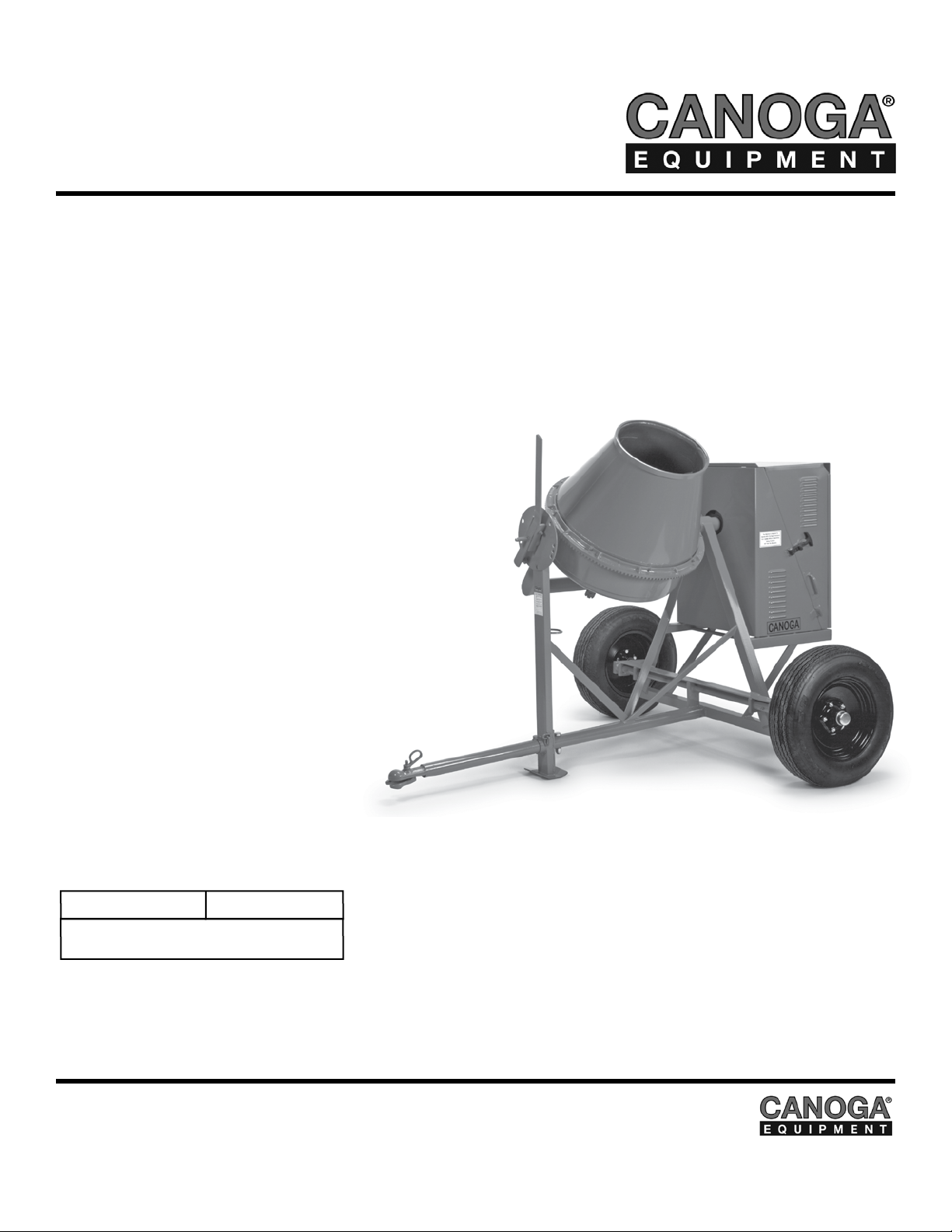
CANOGA 193-E SERIES
CONCRETE MIXER (ELECTRIC)
OPERATOR’S MANUAL
Revision 204
Manual Part No. 166135
Caution: Read all safety and operating instructions
before using this equipment. This manual MUST
accompany the equipment at all times.
08.2013
The Quality Remains Long After The Price Is Forgotten
Page 2
193 SERIES CONCRETE MIXER INTRODUCTION
Congratulations on your purchase of a Canoga Mixer. We are certain that you will be pleased with
your purchase. Canoga takes pride in producing the finest construction power tools and diamond
blades in the industry.
Operated correctly, your Mixer should provide you with years of service. In order to help you, we
have included this manual. This owners manual contains information necessary to operate and
maintain your Mixer safely and correctly. Please take a few minutes to familiarize yourself with the
saw by reading and reviewing this manual.
If you should have questions concerning your saw, please feel free to call our friendly customer service department at: 800 421-5830
Regards,
NOTE THIS INFORMATION FOR FUTURE USE:
MODEL NUMBER:
SERIAL NUMBER:
PURCHASE PLACE:
PURCHASE DATE:
NOTE: For your (1) one year warranty to be effective, complete the warranty
card (including the Serial Number) and mail it in as soon as possible.
2
Page 3

193 SERIES CONCRETE MIXER TABLE OF CONTENTS
CANOGA 193 SERIES CONCRETE MIXER PAGE #
SAFETY
Safety Message/Alert Symbols 4
Hazard Symbols 5
Rules for Safe Operation 6-8
Operation & Safety Decals 10
PRODUCT SPECIFICATIONS
Mixer Dimensions & Decal Locations 11
Product Specications 12
Mixer Basic Components 13
INSPECTION & START-UP
Electric Motor Safety 14-15
Electrical Requirements & Grounding Instructions 16-17
Electric Motor 18
Initial Start-Up (Electric Motor) 18-19
OPERATION
Concrete Mixing 20
Operation 21
Towing Guidelines 22-23
Safety Chain Connection 24
MAINTENANCE & TROUBLESHOOTING
Maintenance (Mixer) 25-27
Troubleshooting (Mixer) 28
GENERAL PRODUCT INFORMATION
Contact Information & Limited Warranty 30
Certicate of Origin for a Vehicle Request Form 31
3
Page 4
193 SERIES CONCRETE MIXER SAFETY
ON
(
(
)
)
ON
(
(
)
)
ON
(
(
)
)
Safety precautions should be followed at all times when operating this equipment. Failure to read and
understand the Safety Precaution and Operating Instructions could result in injury to yourself and oth-
ers.
This Operation Manual has been developed to provide complete instructions for the safe and efcient
operation of the Canoga 193-E Series Concrete Mixer (Electric).
Before using these mixers, ensure that the person operating the mixer has read and understands all instructions in this manual.
SAFETY MESSAGE / ALERT SYMBOLS
A safety message alerts you to potential hazards that could hurt you or others. Each safety message is
preceded by a safety alert symbol ( ) and one of three words: DANGER, WARNING, or CAUTION.
DANGER You WILL be KILLED or SERIOUSLY INJURED if you DO NOT follow directions.
WARNING
You CAN be KILLED or SERIOUSLY INJURED if you DO NOT follow directions.
You CAN be INJURED if you DO NOT follow directions. It may also be used to
CAUTION
alert against unsafe practices.
Each message tells you what the hazard is, what can happen, and what you can do to avoid or reduce injury. Other important messages are preceded by the word NOTICE.
NOTICE
You can cause PROPERTY DAMAGE to your machine if you don’t follow directions.
The safety labels should be periodically inspected and cleaned by the user to maintain good legibility
at a safe viewing distance. If the label is worn, damaged or illegible, it should be replaced.
4
Page 5
193 SERIES CONCRETE MIXER SAFETY
Potential hazards associated with the Canoga 193-E Series Concrete Mixer (Electric) operation will
be referenced with Hazard Symbols which appear throughout this manual, and will be referenced in
conjunction with Safety Message Alert Symbols.
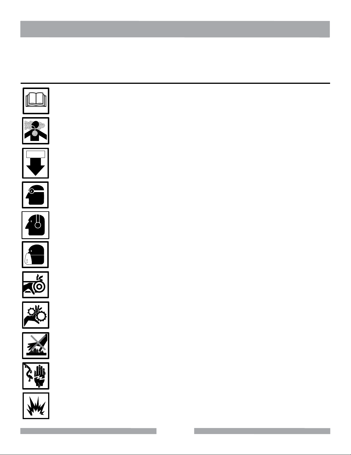
HAZARD SYMBOLS
ALWAYS read this Owner’s Manual before operating the machine.
Avoid inhalation of and skin contact with silica dust and/or mist.
ON / OFF
ALWAYS place the power ON/OFF switch in the OFF position when the mixer is not in use.
ALWAYS wear approved eye protection.
ALWAYS wear approved ear protection.
ALWAYS wear approved respiratory protection.
NEVER operate equipment with covers, or guards removed. Keep ngers, hands, hair
and clothing away from all moving parts to prevent injury.
Use caution around gears. Keep ngers, hands, hair and clothing away from all moving
parts to prevent injury.
DO NOT touch hot engine components while the machine is running or immediately after
operating.
NEVER touch the power cord with wet hands or while standing in water when it is connected to a power source.
NEVER operate the machine in an explosive atmosphere or near combustible materials.
5
Page 6
193 SERIES CONCRETE MIXER SAFETY
ON
(
(
)
)
ON
(
(
)
)
ON
(
(
)
)
ON
(
(
)
)
ON
(
(
)
)
ON
(
(
)
)
ON
(
(
)
)
RULES FOR SAFE OPERATION
DANGER
Failure to follow instructions in this manual may lead to serious injury or even death! This equipment
is to be operated by trained and qualied personnel only! This equipment is for industrial use only. The
following safety guidelines should always be used when operating the Canoga 193-E Concrete Mixer
(Electric).
GENERAL SAFETY
ALWAYS read this Owner’s Manual before operating the machine. DO NOT operate or
service this equipment before reading this entire manual. Read and understand all warnings, instructions and controls on the machine. Know how to stop the equipment quickly in
case of emergency. It is the operators responsibility to use this machine under safe working conditions and conform with federal, state and local codes or regulations pertaining to
safety, air, pollution, noise etc...
This equipment should not be operated by persons under 18 years of age.
NEVER operate this equipment without proper protective clothing, shatterproof
glasses, steel-toed boots and other protective devices required by the job. Non-slip
foot wear is recommended.
NEVER operate this equipment when not feeling well due to fatigue, illness or taking medicine.
NEVER operate this equipment under the inuence of drugs or alcohol.
Whenever necessary, replace nameplate, operation and safety decals when they become
difcult to read.
ALWAYS check the machine for loose bolts before starting.
PERSONAL PROTECTIVE EQUIPMENT
ALWAYS wear approved respiratory (mask), head, hearing and
eye protection when operating the mixer.
NEVER place hands inside the drum while the drum is rotating.
ON / OFF
ALWAYS store equipment properly when it is not being used. Equipment should be stored in
a clean, dry location out of the reach of children
NEVER leave the mixer unattended. Turn off gasoline engine when unattended.
6
Page 7
193 SERIES CONCRETE MIXER SAFETY
ON
(
(
)
)
ON
(
(
)
)
ON
(
(
)
)
ON
(
(
)
)
ON
(
(
)
)
ON
(
(
)
)
ON
(
(
)
)
ON
(
(
)
)
ON
(
(
)
)
ON
(
(
)
)
ON
(
(
)
)
ON
(
(
)
)
ON
(
(
)
)
ON
(
(
)
)
CAUTION must always be observed while servicing this mixer. Rotating parts can cause
injury if contacted.
Ensure that any electrical extension cord is protected against damage. Always ensure that
the electrical extension cord is not trapped underneath the mixer.
DO NOT allow extension cord to come into contact with water or uids. DO NOT spray water onto
electric motor.
DO NOT allow extension cord to come into contact with water or uids. DO NOT spray water onto
electric motor.
This mixer is intended for the production of concrete. Mixer must be used only for its
intended purpose.
This mixer is not suitable for the mixing of ammable or explosive substances.
NEVER operate the mixer in an explosive atmosphere.
Before starting the mixer, check that all guards are in position and correctly tted.
Keep area around the mixer clear of obstructions and trip hazards which could cause
persons to fall onto moving parts.
ALWAYS ensure mixer is on level ground before mixing.
Become familiar with the controls of the mixer before operating.
Ensure the drum is rotating while lling and emptying the drum.
ALWAYS disconnect AC power plug from power source before moving mixer.
Make sure the OFF/ON power switch on the electric motor is always in the OFF position
before inserting the mixer’s power plug into an AC receptacle.
Operate electric motor only at the specied voltage indicated on the nameplate.
7
Page 8
193 SERIES CONCRETE MIXER SAFETY
ON
(
(
)
)
ON
(
(
)
)
ON
(
(
)
)
ON
(
(
)
)
ON
(
(
)
)
ON
(
(
)
)
NEVER disconnect any “emergency or safety devices”. These devices are intended for opera-
tor safety. Disconnection of these devices can cause severe injury, bodily harm or even death!
Disconnection of any of these devices will void all warranties.
Unauthorized equipment modications will void all warranties. Manufacturer does not assume
responsibility for any accident due to equipment modications.
NEVER use accessories or attachments, which are not recommended by Canoga for this equip-
ment. Damage to the equipment and/or injury to user may result.
MAINTENANCE SAFETY
NEVER lubricate components or attempt service on a running machine.
Keep the machinery in proper running condition.
Fix damage to the machine immediately and always replace broken parts or missing decals.
8
Page 9

NOTES
9
Page 10
193 SERIES CONCRETE MIXER SAFETY
WARNING
Maintain
proper tire
pressure.
!
WARNING
Keep hands and
arms out
of tub when
machine is
operational.
!
CAUTION
DO NOT
operate without
guards in place.
!
WARNING
Masonry, concrete, metal and other materials with silica in their composition may give off
dust or mists containing crystalline silica. Silica is a basic component of sand, quartz,
brick clay, granite and numerous other minerals and rocks. Repeated and/or substantial
inhalation of airborne crystalline silica can cause serious or fatal respiratory diseases,
including silicosis. In addition,California and some other authorities have listed respirable
crystalline silica as a substance known to cause cancer.
!
DO NOT operate
this equipment
before reading
the owners’
manual!
WARNING
!
!
CAUTION
Fasten safety
chain before towing
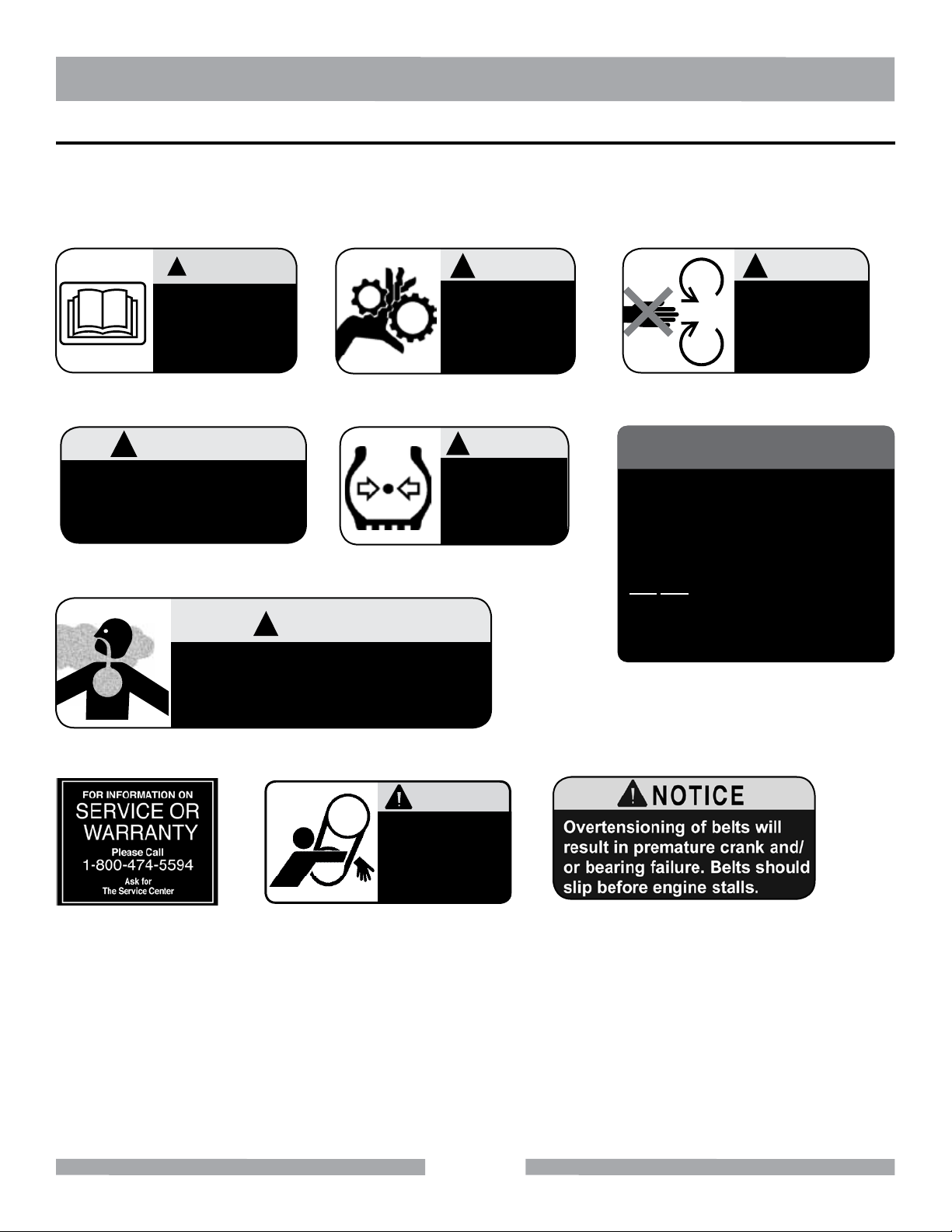
OPERATION & SAFETY DECALS
The Canoga Mixer is equipped with a number of safety decals provided for operator safety and main-
tenance information. Should any of these decals become unreadable, replacements can be obtained
by calling (800) 262-1575.
Decal A Decal B Decal C
NOTICE
Most Motor Problems are caused by improper
voltage and extension cords. Cord should be
one-piece and short as possible. Cord
selection should match the following table.
Decal D Decal E
1-2 H.P.
115v 230v
25’
100’
50’
150’
75’
250’
Max. Cord Length
Max. Cord Length
Max. Cord Length
No. 12 Wire
No. 10 Wire
No. 8 Wire
Decal H Decal I Decal J
Decal G
Decal F
CAUTION
Keep hands
and arms
clear from the
belt drive.
Canoga 193-E Safety Decal Sheet, Part No. 166008
10
Page 11

193 SERIES CONCRETE MIXER DECAL LOCATIONS
MIXER SPECIFICATIONS & DECAL LOCATIONS
Decals Inside: A, F, G, H, I & J
Decals: A, B & C
HEIGHT
67”
Decals: D & E
Decal
A
B
C
D
E
F
G
LENGTH
WIDTH
62”
Mixer Dimensions and Decal Locations
45”
Location Description
Dump Gear Guard and Warning Read Manual Before Operating Equipment
Inside Motor Cabinet
Dump Gear Guard Caution Guards in Place
Dump Gear Guard Warning Keep Hands and Arms Out of Tub
Front Leg Caution Fasten Safety Chain Befoer Towing
Front Leg Warning Maintain Tire Pressure
Inside Motor Cabinet Warning Silica Dust Hazard
Inside Motor Cabinet Notice Extension Cord Warnings
H
Inside Motor Cabinet Service or Warranty Information
I
J
Inside Motor Cabinet Caution Keep Hands and Arm from Belt Drive
Inside Motor Cabinet Notice Do Not Overtension Belts
11
Page 12

193 SERIES CONCRETE MIXER PRODUCT SPECIFICATIONS
SPECIFICATIONS
Canoga 193-E Specications
Model 193-E
Motor* Baldor 1 Hp 120V
Batch Capacity 1/2 to 3/4 Bag (5 cu. ft.)
Total Volume 9 cu.ft.
Drum Diameter 26”
Drum Depth 3/4”
Drum Opening 16”
Drive Single V-belts to cast gear
Axle Torsion-Bar
Wheels 5.0 x 13”
Tires
Dimension
(L x W X H)
Shipping Weight 700 lbs.
Part Number 163821
*See motor manual for complete motor specications.
ST175/80D 13C
6 ply Bias/Load Range C
95” x 62” x 67”
12
Page 13

193 SERIES CONCRETE MIXER PRODUCT SPECIFICATIONS
MIXER BASIC COMPONENTS
C
C
B
A
F
E
D
Mixer Major Components
G
I (on rear of cabinet)
H
A. Steel Mixing Drum – The Canoga concrete mixer uses an 9 cu. ft. steel mixing drum. This
drum is to be used for mixing of concrete. Always clean the drum after each use.
B. Dump Gear Guard – NEVER remove the guarding on the dump guard.
C. Zerk Fittings – Zerk ttings are located at the top of the engine side of the yoke and center of the
drum bearing. Lubricate these ttings as referenced in the maintenance section of this manual.
D. Safety Chain – This mixer uses a 3/16-inch thick, 72-inches long zinc-plated safety chain.
ALWAYS connect the safety chain when towing.
E. Tow Bar – This mixer uses various towing bars. Reference the tow bar drawing on page 9 to
determine which tow bar meets your requirements.
F. Torsion Bar Suspension –This mixer has a torsion bar suspension that should be inspected
periodically.
G. Chock Blocks – Place these blocks (not included as part of the mixer package) under each
mixer wheel to prevent rolling, when mixer is not connected to the towing vehicle.
H. Tires Ply – The tire ply (layers) number is rated in letters. This mixer uses 13-inch 2-ply tires.
Replace with only recommended type tires.
I. Cabinet/Latch – Encloses gas engine. NEVER run mixer with cabinet removed. Use latches to
secure motor compartment cabinet.
13
Page 14

193 SERIES CONCRETE MIXER SAFETY
ON
(
(
)
)
ON
(
(
)
)
ELECTRIC MOTOR SAFETY
For maintenance care and operation of the electric motor, refer to your electric motor instruction booklet furnished with the electric motor. Protect the electric motor from dust as much as possible and keep
ventilating openings clean. Before plugging in the machine, make sure that the outlet voltage is within
the voltage marked on the machines's data plate.
CAUTION
DO NOT spray water on the electric motor. DO NOT touch the plug with wet hands. To reduce
the risk of electrocution, keep all connections dry and off the ground.
DO NOT operate electric motor in an explosive environment.
WARNING
Use only extensions cords that are intended for outdoor use. These extension cords are identied
by a marking, “Acceptable for use with outdoor appliances; store indoors while not in use.” Use only
extension cords having an electrical rating not less than the rating of the product. Do not use damaged extension cords. Examine extension cords before using and replace if damaged. Do not abuse
extension cords and do not yank on any cord to disconnect. Always disconnect the extension cord
from the receptacle before disconnecting the product from the extension cord.
Electric Motor Connection
ALWAYS make certain that the power source required for the electric motor is correct and always
use the correct NEMA conguration plug. Motors can burn out when the line voltage falls 10% below
the voltage rating of the motor. Failure to use proper voltage will cause the motor to overheat. Make
certain that the correct size grounded (3-wires) extension cord is used.
WARNING
Use of undersized extension cords result in low voltage to the motor that can result in motor burnout
and premature failure. Canoga Equipment warns that equipment returned to us showing signs of being run in a low voltage condition, through the use of undersized extension cords,will be repaired or
replaced totally at the customer’s expense. There will be no warranty claim.
14
Page 15

193 SERIES CONCRETE MIXER SAFETY
To choose the proper extension cord,
• Locate the length of extension cord needed in the table below.
• Once the proper length is found, move down the column to obtain the correct
AWG size required for that length of extension cord.
EXTENSION CORD LENGTH
Nameplate
Amperes
0 - 5 16 16 16 14 12 12
5.1 - 8 16 16 14 12 10 •
8.1 - 12 14 14 12 10 • •
12.1 - 15 12 12 10 10 • •
15.1 - 20 10 10 10 • • •
115V 25' 50' 75' 100' 150' 200'
250V 50' 100' 150' 200' 300' 400'
15
Page 16

ON
(
(
)
)
193 SERIES CONCRETE MIXER SAFETY
ELECTRICAL REQUIREMENTS AND GROUNDING INSTRUCTIONS
In order to prevent electrical shock and injury, the following electrical safety precautions and symbols
should be followed at all times!
WARNING
In case of a malfunction or breakdown, grounding provides a path of least resistance for electrical
current to reduce the risk of electric shock. This tool is equipped with an electric cord which has an
equipment-grounding conductor and a grounding plug. The plug must be plugged into a matching
outlet that is properly installed and grounded in accordance with all local codes and ordinances.
• DO NOT modify the plug provided - if it will not t the outlet, have the proper outlet
installed by a qualied electrician.
• Improper connections of the equipment-grounding conductor can result in a risk of electric
shock. The equipment-grounding conductor is the insulated conductor that has an outer
surface that is green, with or without yellow stripes. If repair or replacement of the electric
cord or plug is necessary, DO NOT connect the equipment-grounding conductor to a live
terminal.
• Check with a qualied electrician or service personnel if the grounding instructions are not
completely understood, or if in doubt as to whether the tool is properly grounded.
• Use only 3-wire extension cords that have 3-prong grounding plugs and 3-pole receptacles
that accept the tool’s plug.
• Repair or replace a damaged or worn cord immediately.
This tool is intended for use on a circuit that has an outlet that looks like the one shown in Sketch A.
The tool has a grounding plug that looks like the plug illustrated in Sketch A. A temporary adapter,
which looks like the adapter illustrated in sketches B and C, may be used to connect this plug to a
2-pole receptacle as shown in Sketch B, if a properly grounded outlet is not available. The temporary
adapter should be used only until a properly grounded outlet can be installed by a qualied electri-
cian. The green-colored rigid ear, plug, and the like, extending from the adapter, must be connected
to a permanent ground, such as a properly grounded outlet box.
Metal Screw
Grounding
Pin
(A)
ADAPTER
Grounding
Means
(C)
Cover of
Grounded
Outlet Box
Grounding
Pin
(B)
(D)
Circuit and Adapter Information
Use of a temporary adapter is not permitted in Canada.NOTE:
NOTE:
If permanently connected this tool should be connected to a grounded metal permanent
wiring system; or to a system having an equipment - grounding conductor.
16
Page 17

Surface
ON
(
(
)
)
ON
(
(
)
)
193 SERIES CONCRETE MIXER SAFETY
WARNING
To avoid the possibility of the appliance or plug receptacle getting wet, position the machine to one
side of a wall mounted receptacle. This will prevent water from dripping into the receptacle or plug. A
"drip loop," shown in the picture below, should be arranged by the user to properly position the power
cord relative to the power source. Use the drip loop as a way to prevent GFCI and plug from getting
wet.
The "drip loop" is that part of the cord below the level of the receptacle (or the connector, if an extension cord is used). This method of positioning the cord prevents the travel of water along the power
cord and coming in contact with the receptacle.
If the plug or receptacle gets wet, DO NOT unplug the cord. Disconnect the fuse or circuit breaker
that supplies power to the tool. Then unplug and examine for presence of water in the receptacle.
Power
Cord
Power
Tool
Drip Loop
Supporting
Drip Loop Information
WARNING
Use only extension cords that are intended for outdoor use. These extension cords are
identied by a marking "Acceptable for use with outdoor appliances; store indoors while not
in use." Use only extension cords having an electrical rating not less than the rating of the
product. DO NOT use damaged extension cords. Examine extension cords before using and
replace if damaged. DO NOT abuse extension cords and DO NOT yank on any cord to disconnect. Keep cords away from heat and sharp edges. Always disconnect the extension cord
from the receptacle before disconnecting the product from the extension cord.
ALWAYS make certain that the power source required for the electric motor is correct and always
use the correct NEMA conguration plug. Motors can burn out when the line voltage falls 10% below
the voltage rating of the motor. Failure to use proper voltage will cause the motor to overheat. Make
certain that the correct size grounded (3-wires) extension cord is used.
17
Page 18

193 SERIES CONCRETE MIXER INSPECTION & START-UP
ELECTRIC MOTOR
Refer to motor manual for detailed information.
SINGLE-PHASE
ELECTRIC MOTOR
CONNECT TO GFCI AND THEN
POWER SOURCE
GREASE FITTING
ON/OFF SWITCH
SINGLE-PHASE
ELECTRIC MOTOR
Single Phase Electric Motor with Pigtail Cable
INITIAL START-UP (ELECTRIC MOTOR)
Refer to motor manual for detailed instructions.
CAUTION
DO NOT attempt to operate the mixer until the Safety, General Information and Inspection sections
have been read and understood.
Before starting, make sure mixer is positioned on a secure at surface to prevent rolling.
Use an extension cord of adequate current carrying capacity (see table on Page 15), insert the electric
motor’s power plug into one end of the extension cord. See the Recommended Extension Cord
Sizes table.
18
Page 19

193 SERIES CONCRETE MIXER INSPECTION & START-UP
WARNING
NEVER use a worn or frayed extension cord.
NEVER operate mixer with V-belt cover removed.
DANGER
NEVER touch the power cord with wet hands or while standing in water when it is connected to a
power source. The possibility exists of electrical shock (electrocution) even death. NEVER spray
water directly on the electric motor.
Plug the other end of the extension cord into a 120 VAC G.F.C.I. protected receptacle. Remember the
power requirements for this electric motor is 120 VAC, 60 Hz. The use of any other input voltage will
severely damage the motor.
WARNING
ALWAYS read the label on the electric motor before applying power. The label will indicate the proper
power requirements for the motor. Remember the use of any other input voltage will severely damage the
motor.
ON/OFF SWITCH
To prevent tripping of personnel,
position the extension cord so that it
lays at and is not curled
underneath the mixer.
Set the electric motor’s ON/OFF
switch to the ON position.
19
Page 20

193 SERIES CONCRETE MIXER OPERATION
CONCRETE MIXING
Application
This mixer is only intended for the production of cement concrete. The mixer must be used for its
intended purpose and is not suitable for the mixing of ammable or explosive substances. The mixer
must not be used in an explosive atmosphere. Refer to the reference table below when mixing concrete for various applications.
CONCRETE MIXING HINTS
BATCH QUANTITIES
APPLICATIONS
Most Ordinary 1:2:4 1/2 BAG 1-1/4 35 2-1/2 71 3 85
Foundations 1:3:6 1/3 BAG 1-1/4 35 2-1/2 71 2-3/4 78
Rough Mass
Concrete
Watertight Floors,
Tanks, Pits, Etc.
MIX
RATIOS
1:4:8 1/4 BAG 1-1/4 35 2-1/2 71 2-3/4 78
1:1-1/2:3 2/3 BAG 1-1/4 35 3 71 3 85
CEMENT 112 lbs.
(50 Kgs.)
Bag
SAND STONE
CU. FT. LTR CU. FT. LTR CU. FT. LTR
APPROX. BATCH
OUTPUT
20
Page 21

193 SERIES CONCRETE MIXER OPERATION
OPERATION
To position the drum, make sure the mixer is placed on rm level ground, then pull up on the dump
latch (Figure 1) and turn the hand wheel until the drum is at the desired position. Once the drum is
at the desired position, pull down on the dump latch to lock the drum in position.
CAUTION
NEVER stand in front or behind the mixing drum while it is being placed in the dump position. Stay clear
of the mixing drum while it is being positioned.
As the drum rotates, use a shovel (Figure 2) to place the cement mix inside the drum, add water as
required.
Placing the shovel all the way inside the drum will cause the shovel to strike the blades. This condition
could cause injury to personnel. NEVER place hands inside the mixing drum while it is rotating
(Figure 3).
Fig 1. Mixing Drum Positioning Fig 2. Filling Mixing Drum Fig 3. Filling Mixing Drum
STOPPING THE MIXER
Turn the main start/stop switch to the STOP position.
Push the fuel shut-off lever to the OFF position.
Clear drum of all debris and foreign matter.
21
Page 22

193 SERIES CONCRETE MIXER OPERATION
TOWING GUIDELINES
Check with your county or state safety towing regulations department before
CAUTION
To reduce the possibility of an accident while transporting the mixer on public roads, always make sure that
the mixer towing components and the towing vehicle are in good operating condition and both units are
mechanically sound.
towing your mixer.
CAUTION
Make sure that the hitch and coupling of the towing vehicle are rated equal to, or greater than
the trailer “gross vehicle weight rating” (GVWR).
If the mixer tow bar is deformed or damaged replace entire tow bar. NEVER tow the mixer with
a defective tow bar. There exists the possibility of the trailer separating from the towing vehicle.
ALWAYS inspect the hitch and coupling for wear. NEVER tow the mixer with defective hitches, cou-
plings, chains etc.
CHECK the tire air pressure on both the towing vehicle and the trailer. Also check the tire tread wear
on both vehicles.
ALWAYS make sure the mixer is equipped with a “Safety Chain”.
ALWAYS attach trailer’s safety chain to the frame of towing vehicle.
ALWAYS make sure that the towing vehicle’s directional, backup, and brake lights are working
properly.
The following safety should be used when towing the mixer
Remember in most cases the maximum speed unless otherwise posted for highway towing is
45 MPH, however before towing your mixer, check your local state, and county vehicle towing
requirements. Recommended off-road towing is not to exceed 10 MPH or less depending on
type of terrain.
When towing of the mixer is required, place the drum in the DOWN position (mouth facing
DOWN).
ALWAYS make sure that the fuel valve lever is in the OFF position.
Check wheel mounting lug nuts with a torque wrench. Torque wheel lug nuts as described in
the maintenance section of this manual.
Avoid sudden stops and starts. This can cause skidding, or jackkning.
Avoid sharp turns to prevent rolling.
22
Page 23

193 SERIES CONCRETE MIXER OPERATION
TOWING GUIDELINES
Tow Bar to Vehicle Connection (Coupler Only)
Check the vehicle hitch ball, and mixer’s coupler for signs of wear or damage. Replace any parts that
are worn or damaged before towing.
Use only a 2-inch ball diameter (towing vehicle), this will match the mixer’s 2-inch coupler. Use of any
other ball diameter will create an extremely dangerous condition which can result in separation of the
coupler and ball or ball failure.
After tow bar has been connected to mixer, attach mixer’s coupler to the hitch ball on the towing
vehicle securely and make sure the lock lever is in tight.
Mixer Tow Bar Vehicle Connection (Pintle & Loop)
Make sure the bumper on the towing vehicle is equipped to handle either a pintle or loop type tow bar
conguration.
After tow bar has been connected to mixer, secure either type of tow bar to the towing vehicle,
following state and county towing regulations.
As a minimum, use a 1/2-inch bolt and nylock nut grade 5 when securing either tow bar to the towing
vehicle.
23
Page 24

193 SERIES CONCRETE MIXER OPERATION
SAFETY CHAIN CONNECTION
CAUTION
NEVER tow the mixer with the safety chain removed. The safety chain is intended
to prevent complete separation of the mixer from the towing vehicle in the event
of a tow bar failure. Reference the gure below for the installation of the Safety
Chain.
Tow Bar to Mixer Connection
Insert the tow bar through the round opening at the bottom of the mixer stand. Align the hole on the
tow bar with the hole on the mixer frame, and insert 1/2-inch bolt through tow bar and frame. Secure
tow bar to frame with 1/2-inch nylock nut. Tighten to 40 ft.-lbs.
Route the safety chain through the holes just above the tow bar, located on each side of the mixer
stand. Loop the chain together and place under the tow bar. Secure the loop with the connector link.
Extend the safety chain along the length of the tow bar, looping it through the tow bar’s connector
link. Remove any excess chain slack.
Connect the free end of the safety chain (clevis safety hook) to the towing vehicle. Remember it is
critical that the length of the chain be properly adjusted, to prevent the draw bar and the front of
the mixer stand from dropping to the the ground (contact) in the event the draw bar becomes disconnected from the towing vehicle.
Standard Supplied Tow Bar
Safety
Chain
Mixer
Stand
Tow Bar and Safety Chain Installation
1/2-inch Nylock Nut,
Grade 5
1/2-inch Bolt,
Grade 5
Optional HLC-1 Loop Coupler
24
Page 25

193 SERIES CONCRETE MIXER MAINTENANCE
Ball Socket and Clamp Face Maintenance
If the towing vehicle is equipped with a ball socket, smear socket periodically with multi-purpose
grease. This will keep the ball socket well lubricated.
When parking or storing your mixer. Keep the coupler off the ground so dirt will not build up in the
ball socket.
Grease Fittings (Zerk) Maintenance (Mixer)
There are 2 grease ttings that will require lubrication. Lubricate these ttings once a week.
Use lithium base grease, grade No.1.
BEARING
CONE
WHEEL HUB
OIL
SEAL
BEARING
CUP
Wheel Hub and Bearings
GREASE (ZERK) FITTING
GREASE (ZERK)
FITTING
Grease Fittings
on Mixer
GREASE FITTING
Grease Fittings
on Electric Motor
Use Poleyrex EM (Exxon Mobil) or equalivant lubricant. Clean grease tting, apply grease gun to
tting (1/2 shot). Remember too much grease or injecting grease too quickly can cause premature
bearing failure. Slowly apply the recommended amount of grease, taking a minute or so to apply.
Wheel Bearings
After every 3 months of operation, remove the hub dust cap and inspect the wheel bearings. Once
a year, or when required, disassemble the wheel hubs remove the old grease and repack the bearings forcing grease between rollers, cone and cage with a good grade of high speed wheel bearing
grease (never use grease heavier than 265 A.S.T.M. penetration (“No. 2.”)
Fill the wheel hub with grease to the inside diameter of the outer races and also ll the hub grease
cap. Reassemble the hub and mount the wheel. Then tighten the adjusting nut, at the same time turn
the wheel in both directions, until there is a slight bind to be sure all the bearing surfaces are in contact.
Then back-off the adjusting nut 1/6 to 1/4 turn or to the nearest locking hole or sufciently to allow the
wheel to rotate freely within limits of .001” to .010” end play. Lock the nut at this position. Install the cotter pin and dust cap, and tighten all hardware.
Mixer Cleaning
Always wash drum out after each use.
NEVER pour or spray water over the gas engine.
25
Page 26

193 SERIES CONCRETE MIXER MAINTENANCE
Tires/Wheels/Lug Nuts
Tires and wheels are a very important and critical components of the trailer. When specifying or replacing the trailer wheels it is important the wheels, tires, and axle are properly matched.
CAUTION
DO NOT attempt to repair or modify a wheel. DO NOT install an inter-tube to correct a leak
through the rim. If the rim is cracked, the air pressure in the inter-tube may cause pieces of
the rim to explode (break-off) with great force and can cause serious eye or bodily injury.
Tire Wear/Ination
Tire ination pressure is the most important factor in tire life. Pressure should be checked cold before
operation. DO NOT bleed air from tires when they are hot. Check ination pressure weekly during use
to insure the maximum tire life and tread wear.
The Tire Wear Troubleshooting table will help pinpoint the causes and solutions of tire wear problems.
CAUTION
NOTE: ALWAYS wear safety glasses when removing or installing force tted parts.
Failure to comply may result in serious injury.
Tire Wear Troubleshooting
WEAR PATTERN CAUSE SOLUTION
Center Wear Over ination
Edge Wear Under ination
Loss of
Side Wear
Toe Wear Incorrect toe-in Align wheels.
Cupping Out-of-balance
chamber or overloading
Adjust pressure to particular load per
the manufacturer.
Adjust pressure to particular load per
the manufacturer.
Make sure load does not exceed axle
rating. Align wheels.
Check bearing adjustment and balance tires.
Flat Spots
Wheel lockup & tire
skidding
26
Avoid sudden stops when possible
and adjust brakes.
Page 27

193 SERIES CONCRETE MIXER MAINTENANCE (MIXER)
Lug Nut Torque Requirements
It is extremely important to apply and maintain proper wheel mounting torque on the trailer. Be sure
to use only the fasteners matched to the cone angle of the wheel. Proper procedure for attachment of
the wheels is as follows:
NOTICE NEVER use an pneumatic air gun to tighten wheel lug nuts.
Start all wheel lug nuts by hand using a Torque Wrench.
Torque all lug nuts in sequence. DO NOT torque the wheel lug nuts all the way down.
Tighten each lug nut in 3 separate passes as dened by Troubleshooting table. After rst road use,
retorque all lug nuts in sequence. Check all wheel lug nuts periodically.
Pneumatic Air Gun
Wheel Lug Nuts Tightening SequenceTorque Wrench
Mixer Storage
For storage of the mixer for over 30 days, the following is recommended:
Drain the fuel tank completely, or add STA-BIL to the fuel.
Run the engine until the fuel is completely consumed.
Completely drain used oil from the engine crankcase and ll with fresh clean oil, then follow the
procedures described in the engine manual for engine storage.
Clean the entire mixer and engine compartment.
Place the mixing drum in the down position (mouth facing downward).
Cover the mixer and place it a clean dry area, that is protected from harsh elements.
27
Page 28

193 SERIES CONCRETE MIXER TROUBLESHOOTING
TROUBLESHOOTING
Practically all breakdowns can be prevented by proper handling and maintenance inspections, but in
the event of a breakdown, please take a remedial action following the diagnosis based on the Trouble-
shooting information shown below. If the problem cannot be remedied, please leave the unit just as it is
and consult our company’s business ofce or service center.
Mixer Troubleshooting
SYMPTOM POSSIBLE PROBLEM SOLUTION
Drum rotates rough
Drum does not
rotate at all
Defective ring gear?
Defective pinion gear?
Worn V-belt? Replace V-Belt.
Loose pulley? Tighten or replace pulley.
Fuel?
Broken V-belt? Replace V-belt.
Defective ring or pinion gears?
Check that the ring gear and bearings are
not worn. Replace as necessary.
Check that the pinion gear and bearings
are not worn. Replace as necessary.
Check level of fuel in fuel tank. Add fuel if
necessary. Make sure fuel is being supplied
to the engine. Check to ensure that the fuel
lter is not clogged.
Check that the gears and bearings are not
broken. Replace as necessary.
28
Page 29

NOTES
29
Page 30

193 SERIES CONCRETE MIXER CONTACT & LIMITED WARRANTY
CONTACT
Canoga Equipment is a subsidiary of MK Diamond Products, Inc. Please contact MK Diamond
Customer Service with any questions you might have regarding distributors, parts or service.
Telephone: (800) 421-5830
Fax: (310) 539-5158
E-mail: Customer_Service@MKDiamond.com
Customer Service Hours: Monday through Friday, 6AM-5PM PST
MK Diamond Products, Inc.
1315 Storm Parkway
Torrance, CA 90501
CANOGA LIMITED WARRANTY
MK DIAMOND PRODUCTS, INC. will guarantee every CANOGA® machine they build, to be free
from defects in material and workmanship for (1) one year from date of purchase. The obligation of
MK DIAMOND PRODUCTS, INC. under this warranty is limited to the repair or replacement of any
parts which, under normal use, prove to be defective in material or workmanship. The parts involved
or the unit in question should be returned to MK DIAMOND PRODUCTS, INC. or to a point designated
by us, transportation prepaid.
This warranty does not obligate us to bear the cost of labor or transportation charges in connection
with replacement or repair of defective parts. Likewise, it shall NOT apply to any unit which has been
subjected to misuse, neglect or accident. This warranty does NOT apply to any machine which has
been repaired or altered outside our factory.
This warranty does NOT obligate MK DIAMOND PRODUCTS, INC., with respect to items not of our
manufacture, such as engines, motors, hydraulics, etc., which are subject to their own guarantees and
warranties.
We shall in no event be liable for consequential damages or contingent liabilities arising out of failure
of any equipment or parts to operate properly.
© COPYRIGHT 2013, CANOGA EQUIPMENT. ALL RIGHTS RESERVED.
The Canoga logo is a registered trademark of Canoga Equipment and may not be used, reproduced,
or altered without written permission. All other trademarks are the property of their respective owners
and used with permission.
Canoga Equipment may have patents, patent applications, trade marks, copyrights of other intellectual property right covering this product in this document. This manual MUST accompany the equipment at all times. This manual is considered a permanent part of the equipment and should remain
with the unit if resold.
The information and specications included in this publication were in effect at the time of approval for
printing. Illustrations are based on the Model 193 Concrete Mixer. Illustrations, descriptions, references
and technical data contained in this manual are for guidance only and may not be considered as binding. Canoga reserves the right to discontinue or change specications, design or the information published in this publication at any time without notice and without incurring any obligations.
30
Page 31

®
CANOGA
EQUIPMENT
Check with your county or state for towing regulations before towing your Canoga mixer. If you re-
quire a Certicate of Origin for a Vehicle for your Canoga mixer, please ll out the form and Canoga
will send the necessary paper work to your distributor for them to issue your Certicate.
Manufacturer’s Certicate of Origin form may also be found online at
http://canogamixers.com/vehicle_cert.html
PERSONAL INFORMATION
First Name Last Name
Company Address
Address 2 City
State Zip Code
Email Address Phone
Certicate of Origin for a Vehicle
Request Form
DISTRIBUTOR INFORMATION
Name Address
City State
Zip Code
CANOGA INFORMATION
Model Number Part Number
Serial Number Invoice Number
Date Purchased
Please return the completed form via email, fax or mail. Forms that are not fully completed cannot
be processed.
Fax: (310) 530-3695
Mail: Canoga Products
Customer Service
1315 Storm Parkway
Torrance, CA 90509
Page 32

CANOGA 193-E SERIES
OPERATOR’S MANUAL
MK Diamond Products, Inc.
1315 Storm Parkway
Torrance, CA 90501
Toll-Free: (800) 421-5830
Phone: (310) 539-5221
Fax: (310) 539-5158
www.mkdiamond.com
 Loading...