

Page 1
equipment
OWNER’S MANUAL &
ATS Stand
SETUP INSTRUCTIONS
CAUTION:
Read all safety and
operating instructions
before using this
Page 2
ATS STAND (Document Part Number 158474)
The MK Diamond ATS Stand is designed for use with the following MK Diamond products – MK-100, (Part No.
158189), MK-101 (Part No. 151991), MK-101Pro (Part No. 155747), MK-101 Pro24 (Part No. 153243), MK-115
Pro24 (Part No. 150341), MK-880 (Part No. 153261), MK-1080 (Part No. 153203), MK-2001 (Part No. 150597),
and MK-2002 (Part No. 150598),
NOTE: If problems arise during the assembly of the ATS Stand, contact the MK Diamond Service Center –
(800) 474-5594
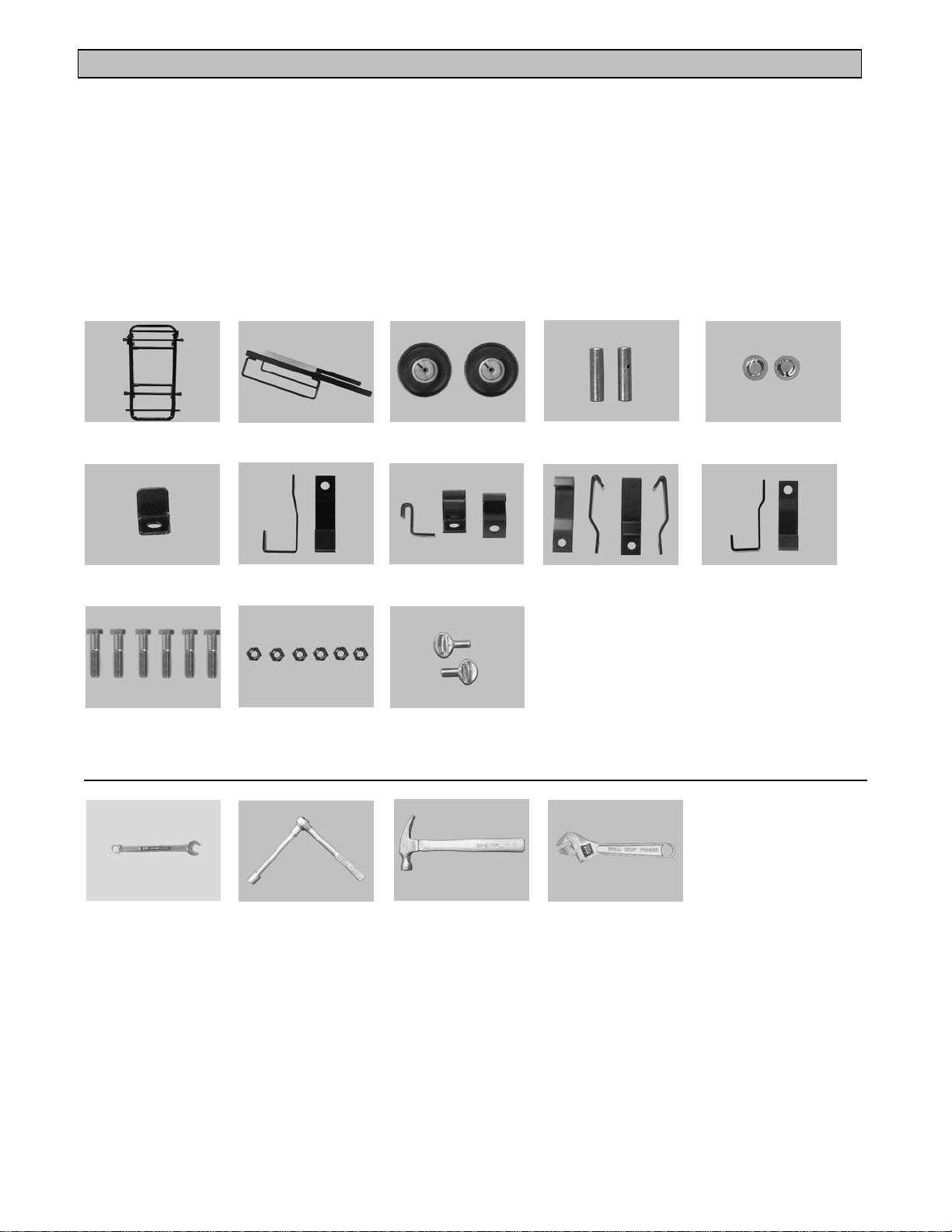
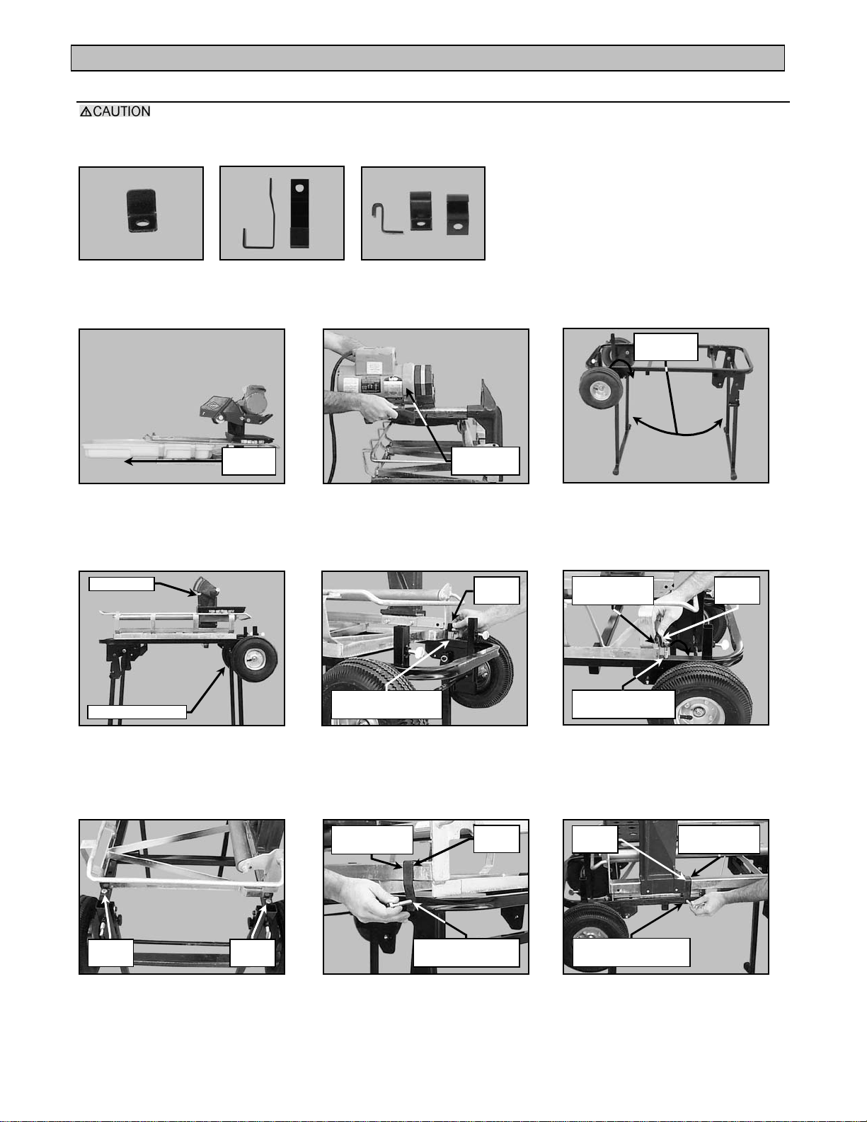
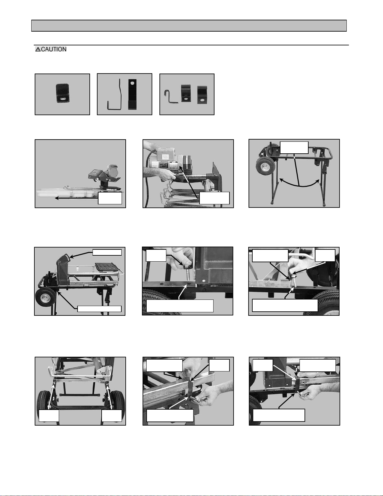
CONTENTS:
one (1) ATS stand frame, one (1) ATS stand support plate, two (2) inflatable tires, two (2) tire retaining caps, one
(1) rear stop/register – A bracket, two (2) B brackets, three (3) C brackets, four (4) D brackets, two (2) F
brackets, six (6) hex-head bolts, six (6) nylock nuts.
ATS Stand
Frame
Rear Stop/Register,
Bracket A (1 ea)
Hex-head Bolts
(6ea)
ATS Stand
Support Plate
Bracket B
(101 series 2ea)
Nylock Nuts
(6ea)
Inflatable
Tires (2ea)
Bracket C (101 &
1080 series 3ea)
Thumbscrews
(2ea)
Shaft Sleeves
(2ea)
Bracket D (2000
series -4ea)
Tire Retaining
Caps (2ea)
Bracket F (1080
series – 2ea)
Tools Needed:
9/16-inch
Wrench
ATS Stand (ATS Stand Part No. – 156426) Revision 04/01, Effective Date: April 11, 2001
9/16-inch Ratchet
with Extension
Hammer Adjustable Wrench
(optional)
Page 2
Page 3
ATS STAND (Document Part Number 158474)
Axle
Shaft Sleeve
clockwise to loosen
Axle
Valve Stem
Axle
Tire
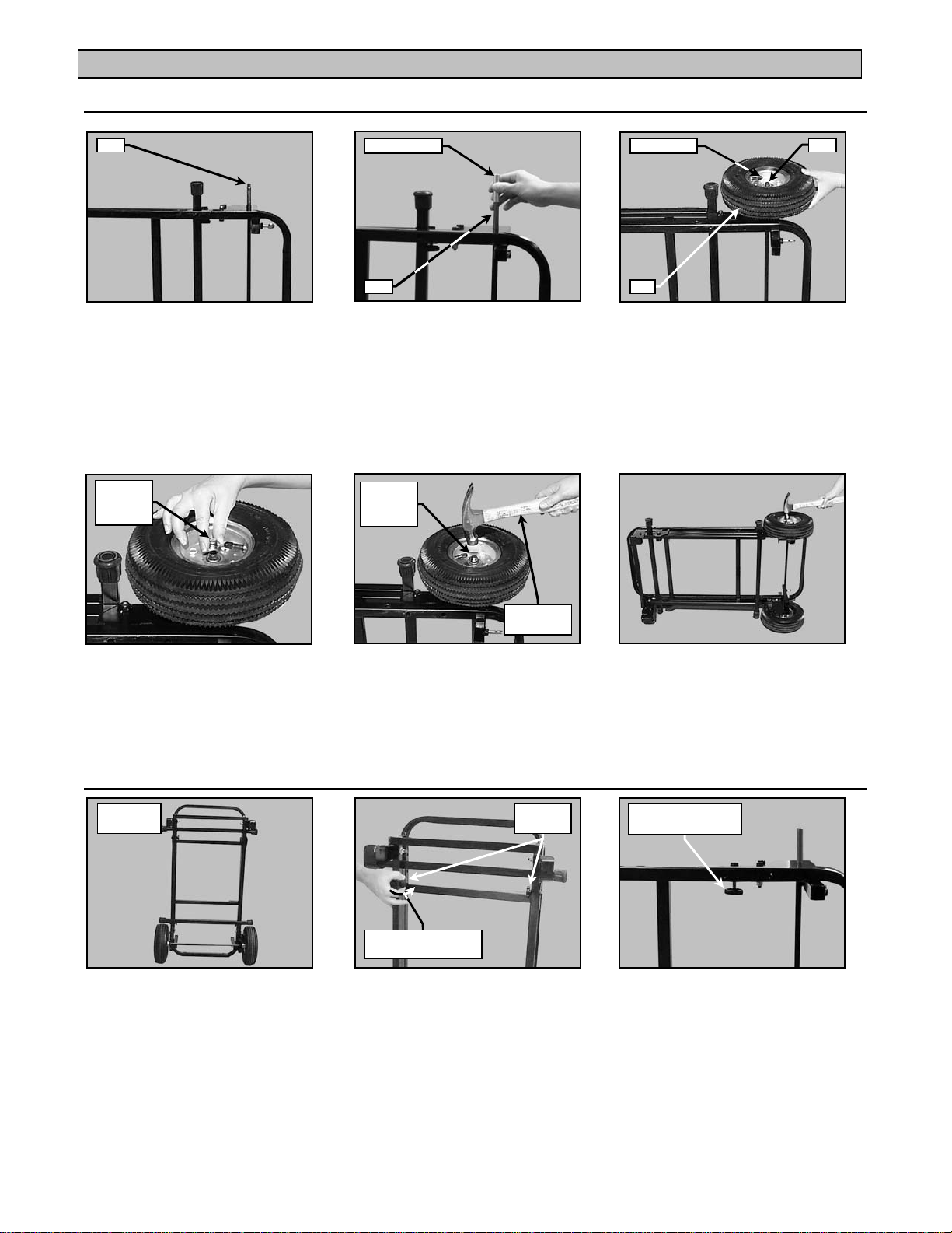
Stand Assembly:
(A)
Place the ATS Stand on its
side and locate the axle
Slide one Shaft Sleeve
(B)
over the axle
(C)
Insert the tire onto the axle with
the valve stem facing out
NOTE: Once the Tire Retaining Cap is installed, it is not easily removed. Ensure the Shaft Sleeve is installed
and the tire is correctly oriented before performing Step D.
Tire
Retaining
Cap
(D)
Position the Tire Retaining
Cap on the axle
Tire
Retaining
Cap
Use gentle
taps to seat
(E)
Using a hammer, seat the
Tire Retaining Cap using
gentle taps
(F)
Repeat Steps A through D
on the opposite side of
the ATS Stand
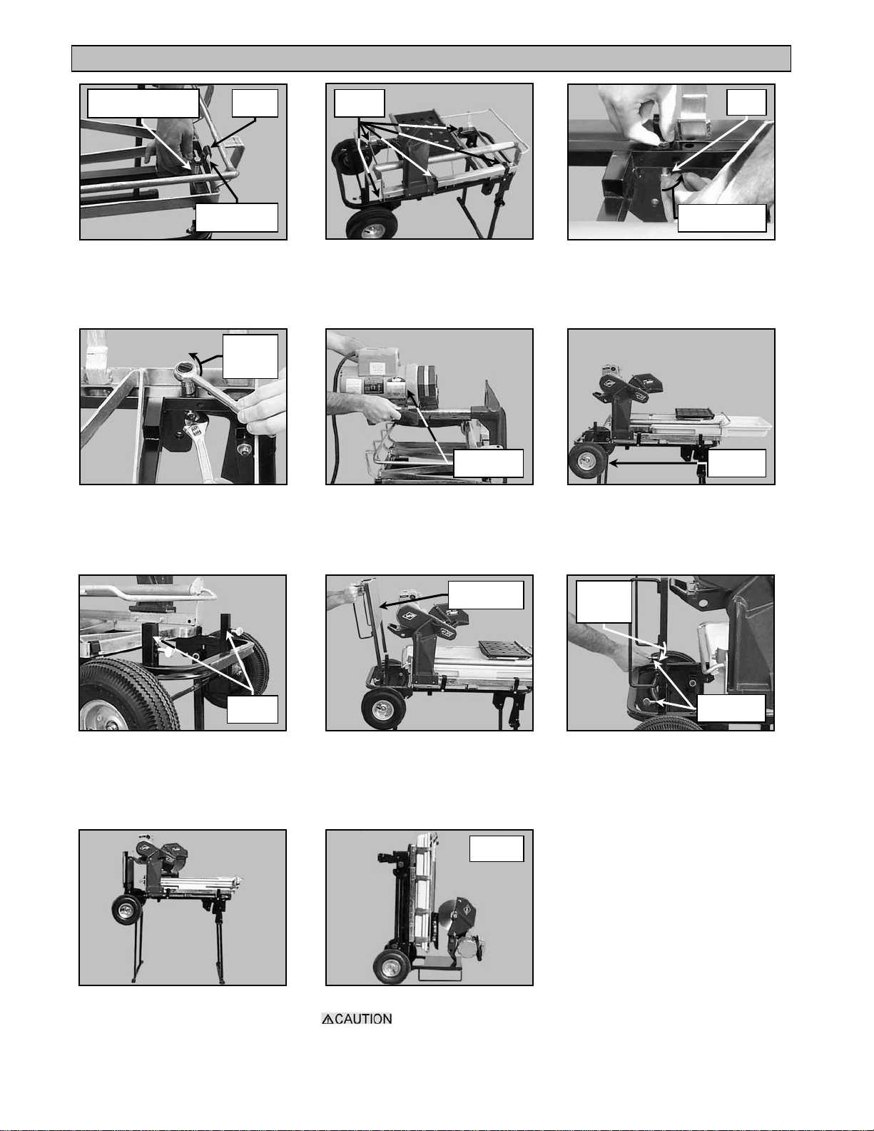
ATS Stand Setup:
u
ATS Stand (ATS Stand Part No. – 156426) Revision 04/01, Effective Date: April 11, 2001
ATS Stand
upright
(A)
Position the ATS Stand in an
upright position
Retaining
Knob
Rotate counter-
(B)
Loosen the two Front Leg
Retaining Knobs
Verify the Retaining
Knob is loose
(C)
Verify the Retaining Knob is
Loose (Do not remove the
Retaining Knob)
Page 3
Page 4
ATS STAND (Document Part Number 158474)
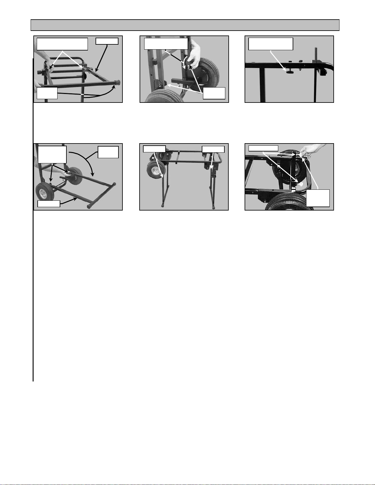
clockwise to loosen
Thumbscrew
Rotate Knob clockwise
to tighten
Rotation
Direction
Front Leg
(D)
Rotate Front Leg up and
tighten the Retaining Knobs
Rotate Knob
clockwise
to tighten
Rear Leg
Rotation
Direction
(G)
Rotate the Rear Leg down and
Tighten the Retaining Knobs
Rotate counter-
(E)
Loosen the two Rear Leg
Retaining Knobs
Rear Leg
(H)
Place ATS Stand on legs
Verify the Retaining
Knob is loose
Retaining
Knob
(F)
Verify the Retaining Knob is
Loose (Do not remove the
Retaining Knob)
Front Leg
Rotate
clockwise
to install
(I)
Install the ATS Stand Support
Plate Thumbscrews
ATS Stand (ATS Stand Part No. – 156426) Revision 04/01, Effective Date: April 11, 2001
Page 4
Page 5
ATS STAND (Document Part Number 158474)
Back of saw
Back of ATS Stand
MK-100, 101, and 101 Pro Normal Cutting Head Position Installation:
To ensure stability, verify front and rear legs of the ATS Stand are fully extended outward before
installing the saw.
NOTE: The following Brackets are required for fastening the saw to the ATS Stand -
1
A Bracket
(A)
Remove Water Pan
B Brackets
Removal
Direction
2
2
C Brackets
Extend legs
outward
Remove
Cutting Head
(B)
Remove the Cutting Head
(See the saw Owners Manual)
Bracket
A
Verify ATS Stand legs are
fully extended for stability
Fit bracket
over saw frame
(C)
Bracket
C
Install into rear hole
on right side of stand
(D)
Seat the saw on the ATS
Stand as shown
Install the Bracket A and a Bolt
into the top, rear, of the ATS
(E)
Stand as shown
Bracket
C
Bracket
(G)
Verify the rear brackets are
installed correctly
Fit bracket
over saw frame
Install into front hole
A
on left side of stand
(H)
Install one B Bracket and a Bolt
into the front, side, of the ATS
Bracket
B
Stand as shown
ATS Stand (ATS Stand Part No. – 156426) Revision 04/01, Effective Date: April 11, 2001
Install into rear hole
on left side of stand
(F)
Install one C Bracket and a Bolt
into the top, rear, of the ATS
Stand as shown
Bracket
B
Install into middle hole
on left side of stand
Fit bracket
over saw frame
(I)
Install one B Bracket and a Bolt
into the rear, side, of the ATS
Stand as shown
Page 5
Page 6
ATS STAND (Document Part Number 158474)
nuts
in the transport position
Position
Install into front hole
on right side of stand
Bracket
C
Fit bracket
over saw frame
(J)
Install one C Bracket and a Bolt
into the top, front, of the ATS
Stand as shown
Rotate
clockwise
to tighten
(M)
Using a 9/16-wrench and socket,
tighten all Bolts
Bracket
locations
(K)
Verify all brackets are installed
Install
Cutting Head
(N)
Install the Cutting Head
(See the saw Owners Manual)
Nylock
Rotate clockwise
to install
(L)
Install one Nylock nut on the Bolt
of each bracket
(Do not cross-thread the nut)
Installation
Direction
(O)
Install the Water Pan
Retaining
Tubes
(P)
Locate the ATS Stand Support
Plate retaining tubes on the back
of the ATS Stand
ATS Stand
Support Plate
(Q)
Orient and install the ATS
Stand Support Plate as shown
Transport
Rotate
clockwise
to tighten
Retaining
Thumbscrew
(R)
Tighten the ATS Stand Support
Plate retaining thumbscrews
as shown
Setup Complete
ATS Stand (ATS Stand Part No. – 156426) Revision 04/01, Effective Date: April 11, 2001
(S)
(T)
Ensure all bolts are
tight before placing the ATS Stand
Page 6
Page 7
ATS STAND (Document Part Number 158474)
Back of saw
Back of ATS Stand
MK-100, 101, and 101 Pro Extended Cutting Head Position Installation:
To ensure stability, verify front and rear legs of the ATS Stand are fully extended outward before
installing the saw.
NOTE: The following Brackets are required for fastening the saw to the ATS Stand -
1
A Bracket
(A)
Remove Water Pan
B Brackets
Removal
Direction
2
2
C Brackets
Extend legs
outward
Remove
Cutting Head
(B)
Remove the Cutting Head
(See the saw Owners Manual)
Bracket
A
Install into second hole from
the end on right side of stand
Verify ATS Stand legs are
fully extended for stability
Fit bracket
over saw frame
Install into second hole from
the end on left side of stand
(C)
Bracket
C
ATS Stand (ATS Stand Part No. – 156426) Revision 04/01, Effective Date: April 11, 2001
(D)
Seat the saw on the ATS
Stand as shown
Bracket
C
Bracket
(G)
Verify the rear brackets are
installed correctly
(E)
Install the Bracket A and a Bolt
into the top, rear, of the ATS
Install one C Bracket and a Bolt
into the top, rear, of the ATS
Stand as shown
Fit bracket
over saw frame
Install into front hole
A
on left side of stand
Bracket
B
Bracket
B
Install into middle hole
on left side of stand
(H)
Install one B Bracket and a Bolt
into the front, side, of the ATS
Install one B Bracket and a Bolt
into the rear, side, of the ATS
Stand as shown
(F)
Stand as shown
Fit bracket
over saw frame
(I)
Stand as shown
Page 7
Page 8

ATS STAND (Document Part Number 158474)
in the transport position
nuts
Position
Bracket
C
Install into front hole
on right side of stand
Fit bracket
over saw frame
(J)
Install one C Bracket and a Bolt
into the top, front, of the ATS
Stand as shown
Rotate
clockwise
to tighten
(M)
Using a 9/16-wrench and socket,
tighten all Bolts
Bracket
locations
(K)
Verify all brackets are installed
Install
Cutting Head
(N)
Install the Cutting Head
(See the saw Owners Manual)
Nylock
Rotate clockwise
to install
(L)
Install one Nylock nut on the
Bolt of each bracket
(Do not cross-thread the nut)
Installation
Direction
(O)
Install the Water Pan
Retaining
Tubes
(P)
Locate the ATS Stand Support
Plate retaining tubes on the back
of the ATS Stand
ATS Stand
Support Plate
(Q)
Orient and install the ATS
Stand Support Plate as shown
Transport
Rotate
clockwise
to tighten
Retaining
Thumbscrew
(R)
Tighten the ATS Stand Support
Plate retaining thumbscrews
as shown
Setup Complete
ATS Stand (ATS Stand Part No. – 156426) Revision 04/01, Effective Date: April 11, 2001
(S)
(T)
Ensure all bolts are
tight before placing the ATS Stand
Page 8
Page 9

ATS STAND (Document Part Number 158474)
Position
ATS Stand handle
Saw Frame
Handle
clockwise to loosen
clockwise to loosen
Transport the MK-100, 101, and 101 Pro using the ATS Stand:
Transport
(A)
ATS Stand in Transport Position
Front of
ATS Stand
(B)
Transport the ATS Stand by the
front of the saw frame or by the
Setup/Takedown of the MK-100, 101, 101 Pro and ATS Stand:
Ensure all bolts are tight before repositioning the ATS Stand.
ATS Stand
Support Plate
Retaining
Knob
Rotate Knob clockwise
to tighten
Front Leg
(A)
Rest ATS Stand on the
Support Plate
Rotate counter-
Retaining
Knob
(D)
Loosen the two Rear Leg
Retaining Knobs
Rotate counter-
(B)
Loosen the two Front Leg
Retaining Knobs
Rotation
Direction
Rotate Knob
clockwise
to tighten
Rear Leg
(E)
Rotate the Rear Leg down and
Tighten the Retaining Knobs
Rotation
Direction
(C)
Rotate Front Leg up and
tighten the Retaining Knobs
Reposition
ATS Stand
(F)
Use proper lifting
techniques when repositioning
the ATS Stand
ATS Stand (ATS Stand Part No. – 156426) Revision 04/01, Effective Date: April 11, 2001
Page 9
Page 10

ATS STAND (Document Part Number 158474)
clockwise to loosen
To ensure stability, verify front and rear legs of the ATS Stand are fully extended outward before
installing the saw.
Extend legs
outward
(G)
Verify ATS Stand legs are
fully extended for stability
ATS Stand
Support Plate
(J)
Install the ATS Stand Support
Plate into the right side of the
ATS Stand as shown
Rotate counter-
Retaining
Thumbscrew
(H)
Loosen the ATS Stand Support
Plate retaining thumbscrews
as shown
(K)
Setup the saw for normal
operation in accordance with
the saw Owners Manual
ATS Stand
Support Plate
(I)
Remove the ATS Stand
Support Plate as shown
NOTE: When work is complete, place the ATS Stand in the transport position by following steps A through J in
reverse order.
ATS Stand (ATS Stand Part No. – 156426) Revision 04/01, Effective Date: April 11, 2001
Page 10
Page 11

ATS STAND (Document Part Number 158474)
Back of saw
Back of ATS Stand
MK-101 Pro and MK-115 Pro:
To ensure stability, verify front and rear legs of the ATS Stand are fully extended outward before
installing the saw.
NOTE: The following Brackets are required for fastening the saw to the ATS Stand -
1
A Bracket
(A)
Remove Water Pan
B Brackets
Removal
Direction
2
2
C Brackets
Extend legs
outward
Remove
Cutting Head
(B)
Remove the Cutting Head
(See the saw Owners Manual)
Bracket
A
Install into second hole from
the end on right side of stand
Verify ATS Stand legs are
fully extended for stability
Fit bracket
over saw frame
Install into second hole from
the end on left side of stand
(C)
Bracket
C
ATS Stand (ATS Stand Part No. – 156426) Revision 04/01, Effective Date: April 11, 2001
(D)
Seat saw on the ATS
Stand as shown
Bracket
C
Bracket
(G)
Verify the rear brackets are
installed correctly
(E)
Install the Bracket A and a Bolt
into the top, rear, of the ATS
Install one C Bracket and a Bolt
into the top, rear, of the ATS
Stand as shown
Fit bracket
over saw frame
Install over front hole
A
on left side of stand
Bracket
B
Bracket
B
Install into rear hole
on left side of stand
(H)
Install one B Bracket and a Bolt
into the front, side, of the ATS
Install one B Bracket and a Bolt
into the rear, side, of the ATS
Stand as shown
(F)
Stand as shown
Fit bracket
over saw frame
(I)
Stand as shown
Page 11
Page 12

ATS STAND (Document Part Number 158474)
in the transport position
nuts
Position
Bracket
C
Install into front hole
on right side of stand
Fit bracket
over saw frame
(J)
Install one C Bracket and a Bolt
into the top, front, of the ATS
Stand as shown
Rotate
clockwise
to tighten
(M)
Using a 9/16-wrench and socket,
tighten all Bolts
Bracket
locations
(K)
Verify all brackets are installed
Install
Cutting Head
(N)
Install the Cutting Head
(See the saw Owners Manual)
Nylock
Rotate clockwise
to install
(L)
Install one Nylock nut on the
Bolt of each bracket
(Do not cross-thread the nut)
Installation
Direction
(O)
Install the Water Pan
Retaining
Tubes
(P)
Locate the ATS Stand Support
Plate retaining tubes on the back
of the ATS Stand
ATS Stand
Support Plate
(Q)
Orient and install the ATS
Stand Support Plate as shown
Transport
Rotate
clockwise
to tighten
Retaining
Thumbscrew
(R)
Tighten the ATS Stand Support
Plate retaining thumbscrews
as shown
Setup Complete
ATS Stand (ATS Stand Part No. – 156426) Revision 04/01, Effective Date: April 11, 2001
(S)
(T)
Ensure all bolts are
tight before placing the ATS Stand
Page 12
Page 13

ATS STAND (Document Part Number 158474)
Position
ATS Stand handle
Saw Frame
Handle
clockwise to loosen
clockwise to loosen
Transport the MK-101 Pro and MK-115 Pro using the ATS Stand:
Transport
(A)
ATS Stand in Transport Position
Front of
ATS Stand
(B)
Transport the ATS Stand by the
front of the saw frame or by the
Setup/Takedown of the MK-101 Pro, MK-115 Pro and ATS Stand:
Ensure all bolts are tight before repositioning the ATS Stand.
ATS Stand
Support Plate
Retaining
Knob
Rotate Knob clockwise
to tighten
Front Leg
(A)
Rest ATS Stand on the
Support Plate
Rotate counter-
Retaining
Knob
(D)
Loosen the two Rear Leg
Retaining Knobs
Rotate counter-
(B)
Loosen the two Front Leg
Retaining Knobs
Rotation
Direction
Rotate Knob
clockwise
to tighten
Rear Leg
(E)
Rotate the Rear Leg down and
tighten the Retaining Knobs
Rotation
Direction
(C)
Rotate Front Leg up and
tighten the Retaining Knobs
Reposition
ATS Stand
(F)
Use proper lifting
techniques when repositioning
the ATS Stand
ATS Stand (ATS Stand Part No. – 156426) Revision 04/01, Effective Date: April 11, 2001
Page 13
Page 14

ATS STAND (Document Part Number 158474)
clockwise to loosen
To ensure stability, verify front and rear legs of the ATS Stand are fully extended outward before
installing the saw.
Extend legs
outward
(G)
Verify ATS Stand legs are
fully extended for stability
ATS Stand
Support Plate
(J)
Install the ATS Stand Support
Plate into the right side of the
ATS Stand as shown
Rotate counter-
Retaining
Thumbscrew
(H)
Loosen the ATS Stand Support
Plate retaining thumbscrews
as shown
(K)
Setup the saw for normal
operation in accordance with
the saw Owners Manual
ATS Stand
Support Plate
(I)
Remove the ATS Stand
Support Plate as shown
NOTE: When work is complete, place the ATS Stand in the transport position by following steps A through J in
reverse order.
ATS Stand (ATS Stand Part No. – 156426) Revision 04/01, Effective Date: April 11, 2001
Page 14
Page 15

ATS STAND (Document Part Number 158474)
Back of saw
Back of ATS Stand
MK-1080 and MK-880:
To ensure stability, verify front and rear legs of the ATS Stand are fully extended outward before
installing the saw.
NOTE: The following Brackets are required for fastening the saw to the ATS Stand -
1
A Bracket
Removal
Direction
(A)
Remove Water Pan
3
C Brackets
2
F Brackets
Remove
Cutting Table
(B)
Remove the Cutting Table
(See the saw Owners Manual)
Bracket
A
Install into second hole from
the end on right side of stand
Extend legs
outward
(C)
Verify ATS Stand legs are
fully extended for stability
Bracket
A
Install one F Bracket and a Bolt
ATS Stand (ATS Stand Part No. – 156426) Revision 04/01, Effective Date: April 11, 2001
(D)
Seat saw on the ATS
Stand as shown
Fit bracket
over saw frame
Install into middle hole
on left side of stand
Bracket
F
(G)
into the rear, side, of the ATS
Stand as shown
(E)
Install the Bracket A and a Bolt
into the top, rear, of the ATS
Stand as shown
Fit bracket
over saw frame
Install into front hole
on left side of stand
Bracket
F
(H)
Install one F Bracket and a Bolt
into the front, side, of the ATS
Stand as shown
(F)
Verify the rear bracket is
installed correctly
Bracket
F
(I)
Verify the two F Brackets
are installed correctly
Page 15
Page 16

ATS STAND (Document Part Number 158474)
in the transport position
Position
of stand
nuts
Bracket
C
Fit bracket
over saw frame
Install into top
rear hole on
right side of stand
(J)
Install one C Bracket and a Bolt
into the top, front, of the ATS
Stand as shown
Nylock
Rotate
clockwise
to tighten
(M)
Install one Nylock nut on the
Bolt of each bracket
(Do not cross-thread the nut)
Fit bracket
over saw frame
Install into top
hole on right side
Bracket
C
(K)
Install one C Bracket and a Bolt
into the top, rear, of the ATS
Stand as shown
Rotate clockwise
to install
(N)
Using a 9/16-wrench and socket,
tighten all Bolts
Bracket
locations
(L)
Verify all brackets are installed
Installation
Direction
(O)
Install Water Pan
Retaining
Tubes
(P)
Locate the ATS Stand Support
Plate retaining tubes on the back
of the ATS Stand
Install
Cutting Table
(S)
Install the Cutting Table
(See the saw Owners Manual)
ATS Stand
Support Plate
(Q)
Orient and install the ATS
Stand Support Plate as shown
(T)
Setup Complete
Rotate
clockwise
to tighten
Retaining
Thumbscrew
(R)
Tighten the ATS Stand Support
Plate retaining thumbscrews
as shown
Transport
(U)
Ensure all bolts are
tight before placing the ATS Stand
ATS Stand (ATS Stand Part No. – 156426) Revision 04/01, Effective Date: April 11, 2001
Page 16
Page 17

ATS STAND (Document Part Number 158474)
Position
ATS Stand handle
Saw Frame
Handle
clockwise to loosen
clockwise to loosen
Transport the MK-1080 and MK-880 using the ATS Stand:
Transport
(A)
ATS Stand in Transport Position
Front of
ATS Stand
(B)
Transport the ATS Stand by the
front of the saw frame or by the
Setup/Takedown of the MK-1080, MK-880 and ATS Stand:
Ensure all bolts are tight before repositioning the ATS Stand.
ATS Stand
Support Plate
Retaining
Knob
Rotate Knob clockwise
to tighten
Front Leg
(A)
Rest ATS Stand on the
Support Plate
Rotate counter-
Retaining
Knob
(D)
Loosen the two Rear Leg
Retaining Knobs
Rotate counter-
(B)
Loosen the two Front Leg
Retaining Knobs
Rotation
Direction
Rotate Knob
clockwise
to tighten
Rear Leg
(E)
Rotate the Rear Leg down and
Tighten the Retaining Knobs
Rotation
Direction
(C)
Rotate Front Leg up and
tighten the Retaining Knobs
Reposition
ATS Stand
(F)
Use proper lifting
techniques when repositioning
the ATS Stand
ATS Stand (ATS Stand Part No. – 156426) Revision 04/01, Effective Date: April 11, 2001
Page 17
Page 18

ATS STAND (Document Part Number 158474)
clockwise to loosen
To ensure stability, verify front and rear legs of the ATS Stand are fully extended outward before
installing the saw.
Extend legs
outward
(G)
Verify ATS Stand legs are
fully extended for stability
ATS Stand
Support Plate
(J)
Install the ATS Stand Support
Plate into the right side of the
ATS Stand as shown
Rotate counter-
Retaining
Thumbscrew
(H)
Loosen the ATS Stand Support
Plate retaining thumbscrews
as shown
(K)
Setup the saw for normal
operation in accordance with
the saw Owners Manual
ATS Stand
Support Plate
(I)
Remove the ATS Stand
Support Plate as shown
NOTE: When work is complete, place the ATS Stand in the transport position by following steps A through J in
reverse order.
ATS Stand (ATS Stand Part No. – 156426) Revision 04/01, Effective Date: April 11, 2001
Page 18
Page 19

ATS STAND (Document Part Number 158474)
Back of saw
Back of ATS Stand
MK-2000 Series:
To ensure stability, verify front and rear legs of the ATS Stand are fully extended outward before
installing the saw.
NOTE: The following Brackets are required for fastening the saw to the ATS Stand -
1
A Bracket
Removal
Direction
(A)
Remove Water Pan
4
D Brackets
Remove
Cutting Table
(B)
Remove the Cutting Table
(See the saw Owners Manual)
Bracket
A
Install into rear hole on
the right side of stand
Extend legs
outward
(C)
Verify ATS Stand legs are
fully extended for stability
Bracket
A
Install one D Bracket and a Bolt
ATS Stand (ATS Stand Part No. – 156426) Revision 04/01, Effective Date: April 11, 2001
(D)
Seat saw on the ATS
Stand as shown
Bracket
D
Install into rear hole
on right side of stand
Fit bracket
over saw frame
(G)
into the rear, side, of the ATS
Stand as shown
(E)
Install the Bracket A and a Bolt
into the top, rear, of the ATS
Stand as shown
Bracket
D
Install into front hole
on right side of stand
Fit bracket
over saw frame
(H)
Install one D Bracket and a Bolt
into the front, side, of the ATS
Stand as shown
(F)
Verify the rear bracket is
installed correctly
Bracket
D
(I)
Verify the two right-side D
Brackets are installed correctly
Page 19
Page 20

ATS STAND (Document Part Number 158474)
nuts
in the transport position
Position
Bracket
D
Install into rear hole
on left side of stand
Fit bracket
over saw frame
(J)
Install one D Bracket and a Bolt
into the rear, side, of the ATS
Stand as shown
Nylock
Rotate clockwise
to install
(M)
Install one Nylock nut on the
Bolt of each bracket
(Do not cross-thread the nut)
Bracket
D
Install into front hole
on left side of stand
Fit bracket
over saw frame
(K)
Install one D Bracket and a Bolt
into the front, side, of the ATS
Stand as shown
Rotate
clockwise
to tighten
(N)
Using a 9/16-wrench and socket,
tighten all Bolts
Bracket
D
(L)
Verify the two left-side D Brackets
are installed correctly
Installation
Direction
(O)
Install the Water Pan
Retaining
Tubes
(P)
Locate the ATS Stand Support
Plate retaining tubes on the back
of the ATS Stand
ATS Stand
Support Plate
(Q)
Orient and install the ATS
Stand Support Plate as shown
Transport
Rotate
clockwise
to tighten
Retaining
Thumbscrew
(R)
Tighten the ATS Stand Support
Plate retaining thumbscrews
as shown
Setup Complete
ATS Stand (ATS Stand Part No. – 156426) Revision 04/01, Effective Date: April 11, 2001
(P)
(Q)
Ensure all bolts are
tight before placing the ATS Stand
Page 20
Page 21

ATS STAND (Document Part Number 158474)
Position
ATS Stand handle
clockwise to loosen
Saw Frame
Handle
clockwise to loosen
Transport the MK-2000 using the ATS Stand:
Transport
(A)
ATS Stand in Transport Position
(B)
Transport the ATS Stand by the
Front of
ATS Stand
front of the saw frame or by the
Setup/Takedown of the MK-2000 and ATS Stand:
Ensure all bolts are tight before repositioning the ATS Stand.
ATS Stand
Support Plate
Retaining
Knob
Rotate Knob clockwise
to tighten
(A)
Rest ATS Stand on the
Support Plate
Rotate counter-
Retaining
Knob
(D)
Loosen the two Rear Leg
Retaining Knobs
Rotate counter-
(B)
Loosen the two Front Leg
Retaining Knobs
Rotation
Direction
Rear Leg
Rotate Knob
clockwise
to tighten
(E)
Rotate the Rear Leg down and
Tighten the Retaining Knobs
Front Leg
Rotation
Direction
(C)
Rotate Front Leg up and
tighten the Retaining Knobs
Reposition
ATS Stand
(F)
Use proper lifting
techniques when repositioning
the ATS Stand
ATS Stand (ATS Stand Part No. – 156426) Revision 04/01, Effective Date: April 11, 2001
Page 21
Page 22

ATS STAND (Document Part Number 158474)
clockwise to loosen
To ensure stability, verify front and rear legs of the ATS Stand are fully extended outward before
installing the saw.
Extend legs
outward
(G)
Verify ATS Stand legs are
fully extended for stability
ATS Stand
Support Plate
(J)
Install the ATS Stand Support
Plate into the right side of the
ATS Stand as shown
Rotate counter-
Retaining
Thumbscrew
(H)
Loosen the ATS Stand Support
Plate retaining thumbscrews
as shown
(K)
Setup the saw for normal
operation in accordance with
the saw Owners Manual
ATS Stand
Support Plate
(I)
Remove the ATS Stand
Support Plate as shown
NOTE: When work is complete, place the ATS Stand in the transport position by following steps A through J in
reverse order.
ATS Stand (ATS Stand Part No. – 156426) Revision 04/01, Effective Date: April 11, 2001
Page 22
 Loading...