

MK SENTRY RCBO User Manual
SENTRY®RCBO
(Residual Current Operated
Circuit Breaker with Integral
Over-Current Protection)
Contents
A Introduction 2
B Product Range 3
C Product Specification 4
D Standards Compliance 6
E Safety Instructions 6
F Installation - General Notes 8
G Installation 10
H Testing 11
I Tripping in Service 14
J Guarantee 15
Please leave this leaflet with the
end user for future reference
52778PL Rev BB
2
ln this range of Single Module Width RCBO’s, each
product provides dual protection; from Over-current via
its MCB section, and from Earth Leaking Fault Current
(Residual Current) via its RCD section.
These devices provide RCD protection in full
compliance with the requirements of the Standard
BS EN 6100 9-1. They also provide very effective RCD
protection in the Supply Voltage Range of 110V to
253V a.c., meeting the requirements of the Standard
for sensitivity and trip speed at
IΔ
n
and 2IΔn.
They meet the requirement of the current edition of the
UK Wiring Regulations (BS 7671), as regards ability to
trip with Earth Loop Impedance of up to 1667 Ω (for a
30mA RCD), by being able to operate with Earth Loop
Impedance of up to 10,000 Ω.
A. INTRODUCTION
5
Mechanical
Terminal Capacity Line in - 25mm
2
Line and Neutral out - 25mm
2
Product Width 18mm
Product Height above 76mm
Din Rail
Product Length 118mm
Suitable Mounting MK Sentry Consumer Unit
Enclosure (select from the MK range)
Method of Mounting Top Hat Mounting (DIN)
in Enclosure Rail to EN 50022
Environmental
Ambient Temperature Range-5°C to +40°C
Storage Temperature Range-30°C to +85°C
Protection, Un-installed Device IP 20
Protection, Installed in the
Consumer Unit IP 40
C. PRODUCT SPECIFICATION (Cont.)
6
The products in this range comply with the requirements of the
following standards:
BS EN 61009-1
BS IEC 61009-2-2
EN 61543 for EMC
D. STANDARDS COMPLIANCE
1. This product must be installed by a competent person (e.g. a
qualified electrician) in accordance with these instructions and
the appropriate clauses of the current edition of the IEE Wiring
Regulations (BS7671) and Building Regulations.
2. The RCBO must be installed within a SENTRY
®
Consumer Unit
(select from the range of MK consumer units).
3. The RCBO should not be regarded as a substitute for basic safety
precautions.
4. Test the RCBO quarterly, as detailed in the current edition of the IEE
Wiring Regulations (BS 7671), by pressing the TEST BUTTON marked
T, provided on the product (see label on the Consumer Unit).
E. SAFETY INSTRUCTIONS
7
Do not use the product if
it fails to trip during this
operation. Failure to trip
indicates either no supply to
the RCBO or a faulty device.
Consult a qualified electrician
or contact MK Technical Sales
and Service Department.
Telephone:
01268 563720
(National)
+44 (0) 1268 563758 (I nternational)
5. Choose an RCBO from TABLE 1,
with the correct ratings, for the
circuit to be protected.
6. The RCBO’s in this range must
not be used in ambient
temperatures outside their
specified range.
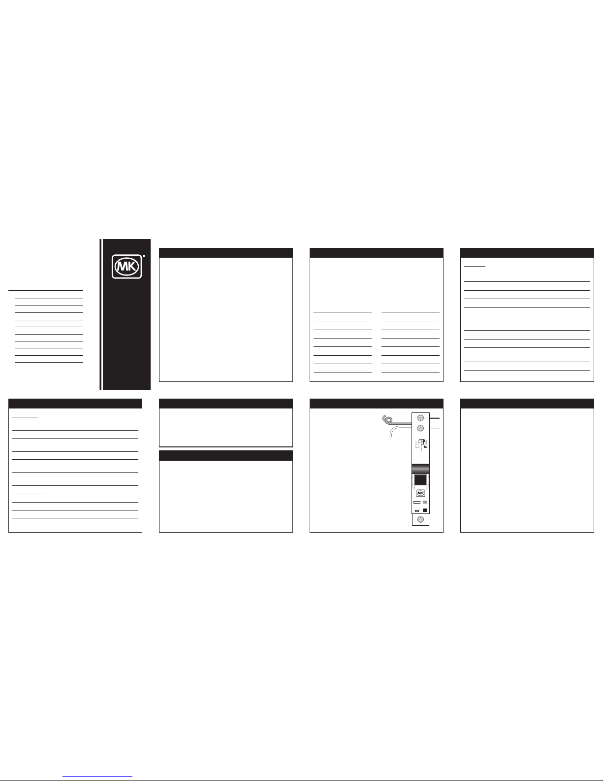
L
IN
N
OUT
L
O
UT
I∆n 30mA
6000
3
230V
B32
7936s
ON
BS EN61009-1
Load
N
OUTLOUT
N
IN-Supply
(Blue)
FE
(White)
L
IN-Supply
Blue Flying
Curled Neutral
Supply Lead
White or
Cream
Flying Earth
Supply Lead
Line Supply
E. SAFETY INSTRUCTIONS (Cont.)
8
1. The RCBO shall be installed at the source of the circuit
in which the Earth Fault and Over-current protection is
required.
2. The RCBO’s may be installed alongside other SENTRY
®
Modular Products, as part of a larger assembly.
3. The RCBO is a sensitive device designed for fixed
installation in a clean and dry environment. The device
must not be installed as part of a portable system which
may be subject to mechanical shocks and vibration.
4. An adhesive label giving test instructions is provided
with each RCBO. This label shall be placed in a
prominent position close to the RCBO (preferably on the
Consumer Unit Cover).
5. Upon completion of the installation, please leave this
instruction leaflet in close proximity to the RCBO, for
future reference.
F. INSTALLATION - GENERAL NOTES
4
Electrical
Number of Poles Single Pole with Solid
Neutral
Rated Supply Voltage 230V a.c. +10%, -15%
Supply Voltage Range 110 V to 253Va.c.
Supply Frequency Range 45 to 66Hz
Supply Voltage Range for 195V to 253V a.c.
Test Device Operation
RCD Trip Current Rating 30 mA
Operating Characteristics Type AC
MCB Type B, C
Rated Short Circuit 6 kA
Capacity Icn
Neutral Connection Flying Lead
Earth Connection Flying Lead
C. PRODUCT SPECIFICATION
3
The product range is given in Table 1 below.
All products in the range have an RCD trip current
rating of 30mA.
Table 1
Type B RCBO Type C RCBO
List No. MCB Current List No. MCB Current
Rating A Rating A
07932s 6 08932s 6
07933s 10 08933s 10
07934s 16 08934s 16
07935s 20 08935s 20
07936s 32 08936s 32
07937s 40 08937s 40
07938s 45 08938s 45
07939s 50 08939s 50
B. PRODUCT RANGE
Figure 1
16
MK Electric Limited
The Arnold Ce ntre, Paycocke Road,
Basildon, Essex SS14 3EA
Telephone: 012 68 563000 (National)
Fax: 01268 563563 (UK Sales)
+44 (0) 1268 563360 (International)
Email: mk.technical@honeywell.com
Web site: www.mkelectric.co.uk
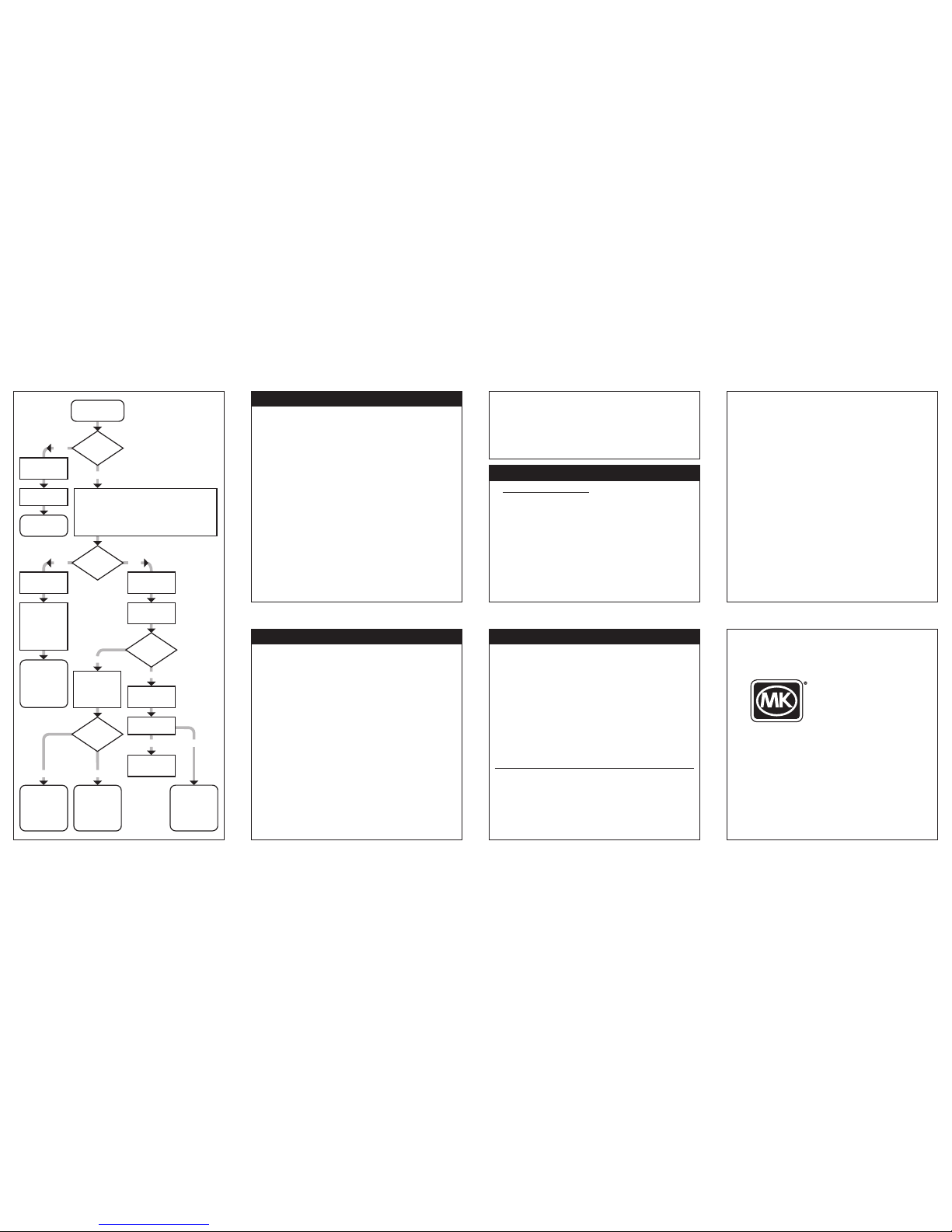
RCBO
tripped / off
NO
Can
RCBO be
switched on
again?
Switch off or disconnect all loads and/or appliances
protected by the RCBO. Inspect all items that were
connected to the RCBO circuit and do not
re-connect any items which show obvious signs of
being faulty (unusual visual signs or smell of
overheating or other faults).
Call a qualified Electrician to investigate further.
Y
ES
Can
R
CBO be
s
witched on
again?
C
heck RCBO
operation with
test button
Transient
Fault
If tripping
re-occurs seek
expert attention
Expert attention
is needed to
correct fault
Check RCBO
is correctly
connected
Can
RCBO be
switched on
again?
Check RCBO
operation with
test button
Check RCBO
operation with
test button
Does RCBO
trip?
Fault rectified
by wiring
correction
Can
RCBO be
switched on
again?
Switch on or
reconnect loads
or appliances
one-by-one
until RCBO
trips off
This load or
appliance is
faulty. Expert
attention is
needed to
correct fault
Disconnect the
RCBO from the
circuit it is
protecting
(Load side only)
There is a
fault within the
load circuit.
Expert attention
needed to
correct fault
Switch off.
Do not use.
Contact MK
Technical Sales
Services
Switch off
RCBO.
Do not use.
Contact MK
Technical Sales
Services
YES NO
YES
YES
NO
NO
NO
YES
9
10
1. Choose and install a suitable enclosure from the Range of MK
Sentry Consumer Units.
2. Mount the RCBO(s) on to the DIN rail in the enclosure with the
L (Supply) terminal at the bottom (shown in Figure 1).
3. It is important that the RCBO is supplied via a Double Pole
Isolator (Switch Disconnector).
4. Strip the Supply Neutral Cable and the Load Cables to expose
11mm of conductor.
5. Connect the Supply Line to the Line (Supply) Terminal at the
bottom, using the busbar supplied with the Consumer Unit.
Alternatively, a suitable cable can be used, which should be
stripped to expose 12mm of conductor for connection.
6. Connect the Neutral (Blue) flying lead of the RCBO to the
Supply Neutral Terminal Bar.
7. Connect the Earth (Cream) flying lead of the RCBO to the
Supply Earth Terminal Bar.
8. Connect the Load, Line and Neutral connections to the
outgoing terminals at the top of the RCBO, marked L (OUT)
and N (OUT), respectively.
9. Connect the Load Earth conductor to the Earth Terminal Bar.
G. INSTALLATION
11
1. Insulation resistance tests
NOTE: Disconnect the L Load, N Load and Earth before
conducting Insulation resistance testing to avoid
damage to the RCBO unit.
2. After the installation is complete, turn on the supply to the
RCBO and check that the supply voltage to the product is
present at its L (Supply) and N (Supply) connection.
3. Switch on the RCBO by moving its switch dolly upwards to
show ‘ON’ position. Press the Test Button on the device, the
device should trip.
IMPORTANT: Upon completion, ensure that all terminal screws
are tightened to the correct torque values (Load, Line and Neutral
Terminal - 1.2 to 1.5 Nm, Supply Line Terminal - 2.0 to 2.5Nm).
10. Test the RCBO as detailed in Section H of this leaflet.
11. AFFIX LABEL SUPPLIED TO THE SENTRY®CONSUMER UNIT.
12. Leave this Instruction Leaflet with the end user for future use.
H. TESTING
12
4. Carry out the following tests using a calibrated RCD Tester.
Test Current Result
0.5IΔn RCBO must not trip
IΔ
n RCBO must trip within 300 ms
2
IΔ
n RCBO must trip within 200 ms
5
IΔ
n RCBO must trip within 40 ms
If the device fails to trip as required in steps 3. and 4.
above, do not use the product.
Failure to trip according to 3. and 4. above, after it is
confirmed that the supply is present to the product, indicates
to a faulty product. Consult a qualified electrician or contact,
MK Electric Technical Sales and Service Department.
Telephone: 01268 563720 (National)
+44 (0) 1268 563758 (Inter national)
Maintenance
It is recommended that the RCBO is checked regularly, at least
quarterly. Refer to Item 4 in Section E, Safety Instructions, of
this leaflet.
14
If the black portion of the switch is in the ‘OFF’
position, this is an indication that a fault has caused
the RCBO to trip.
Consult the Fault Identification Chart (Figure 2) to
establish the cause.
Any repairs to appliances or alterations to the
installation, to correct the fault, should be carried
out by a competent person.
I. TRIPPING IN SERVICE
15
The Company undertakes to replace or repair, at its discretion,
this product should it become defective within a period of
10 years after delivery, solely as a result of faulty materials
and/or workmanship. Understandably, if the product has not
been installed or maintained in accordance with the
Company’s instructions, has not been used appropriately,
or if any attempt has been made to rectify, dismantle or alter
the product in any way, the guarantee will be invalidated.
This Guarantee states the Company’s entire liability. It does
not extend to cover consequential loss or damage or
installation costs arising from the defective product. This
Guarantee does not restrict or infringe the normal statutory
or other rights of the consumer.
MK Electric Limited wishes to make it clear that it will take
all necessary legal action in any part of the world against
any party found to be manufacturing, distributing, selling or
otherwise dealing with any article which infringes the
company’s design rights, copyrights or patents in its
products, or any other rights of the company therein.
Design Right MK Electric Ltd.
J. GUARANTEE
Figure 2
F
ault Identification
Chart (Section I.)
 Loading...