

MK MK-2013HSP GX390, MK-2020HSP GX630, MK-2024HSP GX360, MK-2014K CH440, MK-2013VSP V-Twin Owner's Manual
...
www.mkdiamond.com
MK-20 SERIES
OWNER’S MANUAL,
Gas Powered
Concrete Saw
OPERATING INSTRUCTIONS
& PARTS LIST
MODELS: MK-2013HSP GX390 Part # 156499
MK-2020HSP GX630 Part # 156498
MK-2024HSP GX360 Part # 158777
MK-2013HE GX390 Part # 155714
MK-2014K CH440 Part # 168798
MK-2013VSP V-Twin Part # 169949
Revision 310
Manual Part# 156777
Caution: Read all safety and operating instructions
before using this equipment. This owner’s manual
MUST accompany the equipment at all times.
02.2017
MK-2024HSP GX360
Part # 158777

INTRODUCTION
Congratulations on your purchase of a MK-20 Series. We are certain that you will be pleased
with your purchase. MK Diamond takes pride in producing the nest construction power tools
and diamond blades in the industry.
Operated correctly, your MK-20 Series should provide you with years of service. In order to
help you, we have included this manual. This owners manual contains information necessary to
operate and maintain your MK-20 Series safely and correctly. Please take the time to familiarize
yourself with the MK-20 Series by reading and reviewing this manual.
Read and follow all safety, operating and maintenance instructions.
If you should have questions concerning your MK-20 Series, please feel free to call our friendly
customer service department at: 800 421-5830
Regards,
MK Diamond
NOTE THIS INFORMATION FOR FUTURE USE:
MODEL NUMBER:
SERIAL NUMBER:
PURCHASE PLACE:
PURCHASE DATE:
NOTE: For your (1) one year warranty to be effective, complete the warranty card
(including the Serial Number) and mail it in as soon as possible.
2

TABLE OF CONTENTS
SAFETY
Safety Messages 4
Damage Prevention Message 4
General Safety Precautions and Hazard Symbols 5
California Proposition 65 Message 8
Prestart Safety 9
Safety Label Locations 10-11
Product Specications 12
UNPACKING, TRANSPORT and ASSEMBLY
Unpacking 13
Contents 13
Transport 14
Assembly 15-16
SET-UP, OPERATION and SHUTDOWN
Set-Up 17-19
Operation 20-23
Shutdown 24
Cleanup 24
MAINTENANCE
Maintenance 25-32
EXPLODED VIEW & PARTS LIST
Figure 1 Assy, Saw 2020HSP Part # 156498 34-38
Figure 2 Assy, Saw 2024HSP Part # 158777 39-44
Figure 3 Frame, Less Engine Part # 169719 45-49
Figure 4 Assy, Blade Shaft Part # 156654 50
Figure 5 Engine, Honda GX630 Part # 169713 51
Figure 6 Engine Honda GX690 Part # 170048 52
Figure 7 Assy, Pointer Part # 166465 53
ACCESSORIES
Accessories 54
ORDERING and RETURN INSTRUCTIONS
Ordering Information 56
Return Material Policy 56
Packaging Instructions 56
Authorized Service Centers 56
Contact Information 57
Warranty 57
3
MK-20 SERIES SAFETY
Safety precautions should be followed at all times when operating this equipment. Failure to read and
understand the Safety Precaution and Operating Instructions could result in injury to yourself and
others.
This Operation Manual has been developed to provide complete instructions for the safe and efcient
operation of the MK-20 Series. For additional instruction concerning engine operations and care refer
to the engine manufacturers instructions.
Before using this saw, ensure that the person operating the equipment has read and understands all
instructions in this manual.
Descriptions, illustrations, and photos are as accurate as possible at the time of publication. Photos
may include optional equipment or accessories and may not show all models covered by this manual.
SAFETY MESSAGE / ALERT SYMBOLS
A safety message alerts you to potential hazards that could hurt you or others. Each safety message is
preceded by a safety alert symbol ( ) and one of three words: DANGER, WARNING, or CAUTION.
DANGER
You WILL be KILLED or SERIOUSLY INJURED if you do not follow directions.
WARNING
You CAN be KILLED or SERIOUSLY INJURED if you do not follow directions.
CAUTION
You CAN be INJURED if you do not follow directions. It may also be used
to alert against unsafe practices.
Each message tells you what the hazard is, what can happen, and what you can do to avoid or
reduce injury. Other important messages are preceded by the word NOTICE.
NOTICE
You can cause PROPERTY DAMAGE to your machine if you don’t follow directions.
The safety labels should be periodically inspected and cleaned by the user to maintain good legibility
at a safe viewing distance. If the label is worn, damaged or illegible, it should be replaced. Contact
MK Diamond or your dealer for replacement.
DAMAGE PREVENTION AND INFORMATION MESSAGES
A Damage Prevention Message is to inform the user of important information and/or instructions that
could lead to equipment or other property damage if not followed. Information messages convey
information that pertains to the equipment being used. Each message will be preceded by the word
note, as in the example below.
NOTE: Equipment and/or property damage may result if these instructions are not followed.
4
MK-20 SERIES SAFETY
(
(
)
)
GENERAL SAFETY PRECAUTIONS AND HAZARD SYMBOLS
SAFETY PRECAUTIONS
In order to prevent injury, the following safety precautions and symbols should be followed
at all times!
GENERAL SAFETY
DO NOT operate or service this equipment before reading this entire manual.
This equipment should not be operated by persons under 18 years of age.
NEVER operate this equipment when not feeling well due to fatigue, illness or taking
medicine.
NEVER operate this equipment under the inuence of drugs or alcohol.
Whenever necessary, replace nameplate, operation and safety decals when they become
difcult to read.
ALWAYS store equipment properly when it is not being used. Equipment should be stored
in a clean, dry location out of the reach of children.
KEEP GUARDS IN PLACE
In order to prevent injury, keep guards in place and in working order at all times.
EXPLOSIVE FUEL!
Gasoline is extremely ammable, its vapors can explode if ignited; store only in approved
containers, in well-ventilated, unoccupied buildings and away from sparks or ames. Do not
ll the fuel tank while the engine is running or hot. Spilled fuel could ignite if it contacts hot
parts or sparks from ignition. Do not start the engine near spilled fuel. Never use gasoline
as a cleaning agent. Never operate the machine in an explosive atmosphere.
LETHAL EXHAUST GASES
Engine exhaust gasses contain poisonous carbon monoxide, an odorless colorless gas
that can cause death if inhaled. Avoid inhaling exhaust fumes, and never run the engine
in a closed building or conned area.
ENGINE OVER-SPEED
Never tamper with the governor components or settings to increase the maximum speed of
the machine. Severe personal injury and/or equipment damage could result if the equipment is operated speeds above design maximum.
5

MK-20 SERIES SAFETY
on
ACCIDENTAL STARTS
Before starting the engine, be sure the ON/OFF switch is in the “OFF” position to prevent
accidental starting. Place the ON/OFF switch in the OFF position before performing any
service operation.
ROTATING OR MOVING PARTS
Keep hands, feet, hair, and clothing away from all moving parts to prevent injury. Never
operate a power tool with shrouds or guards removed.
HOT PARTS
Engine components can become extremely hot from operation. To prevent severe burns, do
not touch these areas while the engine is running, or immediately after it is turned off. Never
operate the engine with heat shields removed.
ALWAYS USE SAFETY GLASSES
Safety glasses should always be worn when working around power tools. Everyday eyeglasses only have impact resistant lenses and may not prevent eye injury; they are NOT
safety glasses.
ALWAYS USE RESPIRATORY PROTECTION
Exhaust gases may be harmful if inhaled. Do not operate gas-powered equipment in
enclosed spaces. Respiratory protection should be worn when operating gas powered
equipment.
ALWAYS USE HEARING PROTECTION
To reduce the possibility of hearing loss, always use hearing protection when operating
equipment.
REMOVE ADJUSTING KEYS AND WRENCHES
Form a habit of checking to see that keys and adjusting wrenches are removed from the power tool
before it is turned on.
KEEP WORK AREA CLEAN
Cluttered work areas and benches invite accidents.
DO NOT USE IN DANGEROUS ENVIRONMENTS
Do not operate equipment in dangerous environments. Always keep the work area well lighted.
KEEP CHILDREN AWAY
All visitors and children should be kept a safe distance from work area.
MAKE WORKSHOP KID PROOF
Make the workshops kid proof by using padlocks, master switches or by removing starter keys.
6

MK-20 SERIES SAFETY
DO NOT FORCE THE TOOL
A power tool will do a job better and safer operating at the rate for which it was designed.
USE THE RIGHT TOOL
Do not force a tool or an attachment, to do a job that it was not designed to do.
WEAR PROPER APPAREL
Do not wear loose clothing, gloves, neckties, rings, bracelets, or other jewelry that may be caught in
moving parts. Nonslip footwear is recommended. Wear protective hair covering to contain long hair.
SECURE WORK
Clamps or a vise should be used to hold work whenever practical. Keeping your hands free to operate a power tool is safer.
DO NOT OVERREACH
Keep proper footing and balance at all times by not overreaching.
MAINTAIN TOOLS WITH CARE
Keep tools sharp and clean for the best and safest performance. Always follow maintenance instructions for lubricating and when changing accessories.
SHUTDOWN TOOL
The saw should always be shutdown before servicing or when changing accessories such as blades,
bits, cutters, etc...
USE RECOMMENDED ACCESSORIES
Consult the owner’s manual for recommended accessories. Using improper accessories may increase the risk of personal or by-stander injury.
NEVER STAND ON THE TOOL
Serious injury could occur if a power tool is tipped, or if a cutting tool is unintentionally contacted.
NEVER LEAVE TOOL RUNNING UNATTENDED – TURN POWER OFF
Do not leave a tool until it comes to a complete stop. Always turn a power tool OFF when leaving the
work area, or, when a cut is nished.
CHECK FOR DAMAGED PARTS
Before using a power tool, check for damaged parts. A guard or any other part that is damaged
should be carefully checked to determine if it would operate properly and perform its intended function
safety. Always check moving parts for proper alignment or binding. Check for broken parts, mountings and all other conditions that may affect the operation of the power tool. A guard or any damaged
part should be properly repaired or replaced.
DIRECTION OF FEED
Always feed work into a blade or cutter against the direction of rotation. A blade or cutter should
always be installed such that rotation is in the direction of the arrow imprinted on the side of the blade
or cutter.
7

MK-20 SERIES SAFETY
ON
(
(
)
)
SILICA DUST WARNING
Grinding/cutting/drilling of masonry, concrete, metal and other materials with silica in their composition
may give off dust or mists containing crystalline silica. Silica is a basic component of sand, quartz,
brick clay, granite and numerous other minerals and rocks. Repeated and/or substantial inhalation of
airborne crystalline silica can cause serious or fatal respiratory diseases, including silicosis. In addition, California and some other authorities have listed respirable crystalline silica as a substance
known to cause cancer. When cutting such materials, always follow respiratory precautions.
Use appropriate NIOSH-approved respiratory protection where dust hazard may occur. Paper masks
or surgical masks without a NIOSH approval number are not recommended because they do little to
protect the worker. For more information about respirator programs, including what respirators have
received NIOSH approval as safe and effective, please visit the NIOSH website at:
http://www.cdc.gov/niosh/topics/respirators
Observe OSHA regulations for respirator use (29 C.F.R.§1910.134).
Visit http://www.osha.gov for more information.
CALIFORNIA PROPOSITION 65 MESSAGE
Some dust created by power sanding, sawing, grinding, drilling, and other construction activities contain chemicals known (to the State of California) to cause cancer, birth defects or other reproductive
harm. Some examples of these chemicals are:
• Lead, from lead-based paints
• Crystalline silica from bricks, cement and other masonry products
• Arsenic and chromium, from chemically treated lumber
For further information, consult the following sources:
http://www.osha.gov/dsg/topics/silicacrystalline/index.html
http://www.cdc.gov/niosh/docs/96-112/
http://oehha.ca.gov/prop65/law/P65law72003.html
http://www.dir.ca.gov/Title8/sub4.html
Your risk from these exposures varies depending on how often you do this type of work. To reduce
your exposure to these chemicals, work in a well-ventilated area, and work with approved safety
equipment, such as dust masks that are specially designed to lter out microscopic particles. Where
use of a dust extraction device is possible, it should be used. To achieve a high level of dust collection, use an industrial HEPA vacuum cleaner. Observe OSHA 29 CFR part 1926.57 and 1926.103.
WARNING
Sawing, grinding and drilling generate dust. Excessive airborne particles may cause irritation to eyes,
skin and respiratory tract. To avoid breathing impairment, always employ dust controls and protection
suitable to the material being sawed or drilled; See OSHA (29 CFR Part 1910.1200).
8

NOTES
9
MK-20 SERIES SAFETY
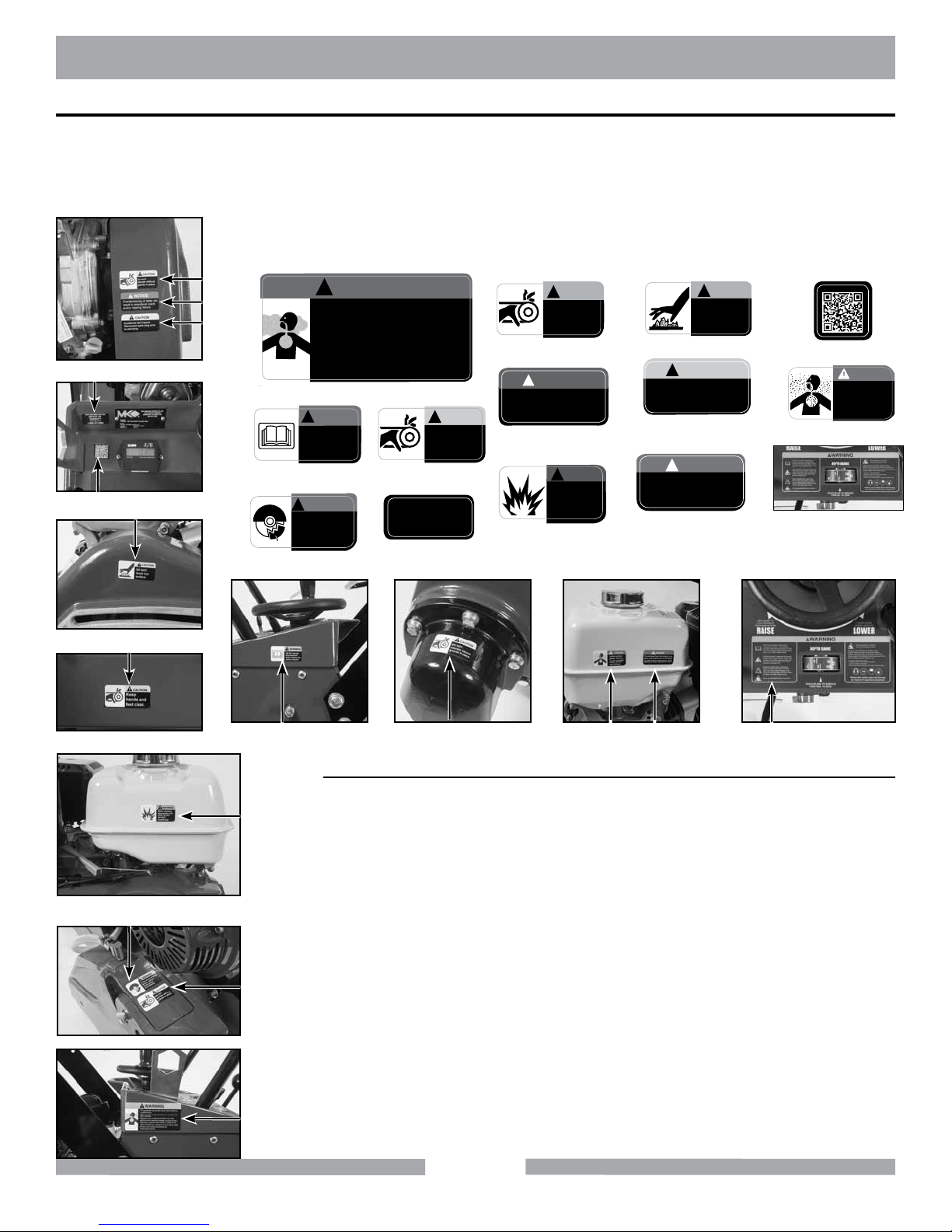
OPERATION & SAFETY DECALS
The MK-20 Series Concrete Saw is equipped with a number of safety decals. These decals are provided for operator safety and maintenance information. Should any of these operation or safety decals become unreadable, replacements can be obtained by calling (800) 262-1575.
Location of Safety Decals for models: MK-2013HE, MK-2013HSP, MK-2013SE,
MK-2013SSP, MK-2013VSP, and MK-2014K
LEI
C
G
A
J
B
Part # 154398
D
Part # 155588
WARNING
!
•Thisequipmentmayproducedustormistscontaining
crystallinesilica.
•Silicaisabasiccomponentofmasonry,concrete,and
othermaterials.
•Repeatedand/orsubstantialinhalationcancause
seriousorfatalrespiratorydiseasesincludingsilicosis.
•RespirablecrystallinesilicaislistedbyCaliforniaand
otherauthoritiesasasubstanceknowntocausecancer.
•Employdustcontrolsandprotectionper
OSHA/NIOSH/MSHA.
Part # 164202
WARNING
!
DO NOT operate
this equipment
before reading the
owner’s manual.
WARNING
!
In the event of blade
failure, replace
blade guard
immediately.
C
Part # 155587 (3)
FOR INFORMATION ON
E
1-800-474-5594
Part # 155038
SERVICE OR
WARRANTY
PLEASE CALL
CAUTION
!
DO NOT
operate without
guards in place.
F
G
Keep
hands and
feet clear.
Part # 155585
NOTICE
!
Overtensioning of belts will
result in premature crank
and/or bearing failure.
Part # 154399
H
Part # 155580
CAUTION
!
WARNING
!
When refueling
stop engine and
allow to cool.
DO NOT
overll tank.
I
Part # 155578
CAUTION
!
Accidental start hazard.
J
Disconnect spark plug prior
to servicing.
Part # 155579
DANGER
!
The exhaust from this product con-
K
tains chemicals known to the State
of California to cause cancer, birth
defects or other reproductive harm.
Part # 155581
CAUTION
!
DO NOT
touch hot
surface.
L
Part # 170480
DANGER
Lethal exhaust
M
gases. Use only
in well ventilated
areas. DO NOT
use indoors.
Part # 155582
N
Part # 156749
F
B
C
M K N
Location Description
A
Gas Tank - Top Warning - Silica
B
H
D
C
A
Frame - Side Read Manual
C
Shaft Cover/Belt Guard/Blade Guard Guards in Place
D
Blade Guard - Top Replace Blade Guard
E
Console Service
F
Frame - Front Hand & Feet Clear
G
Belt Guard - Front Overtensioning Belts
H
Gas Tank - Side Refueling
I
Belt Guard Hot Surface
J
Belt Guard Accidental Start
K
Gas Tank - Side Exhaust/Cancer
L
Console QR Code for Manuals
M
Gas Tank - Side Lethal Exhaust
N
Console Machinery Hazard
10
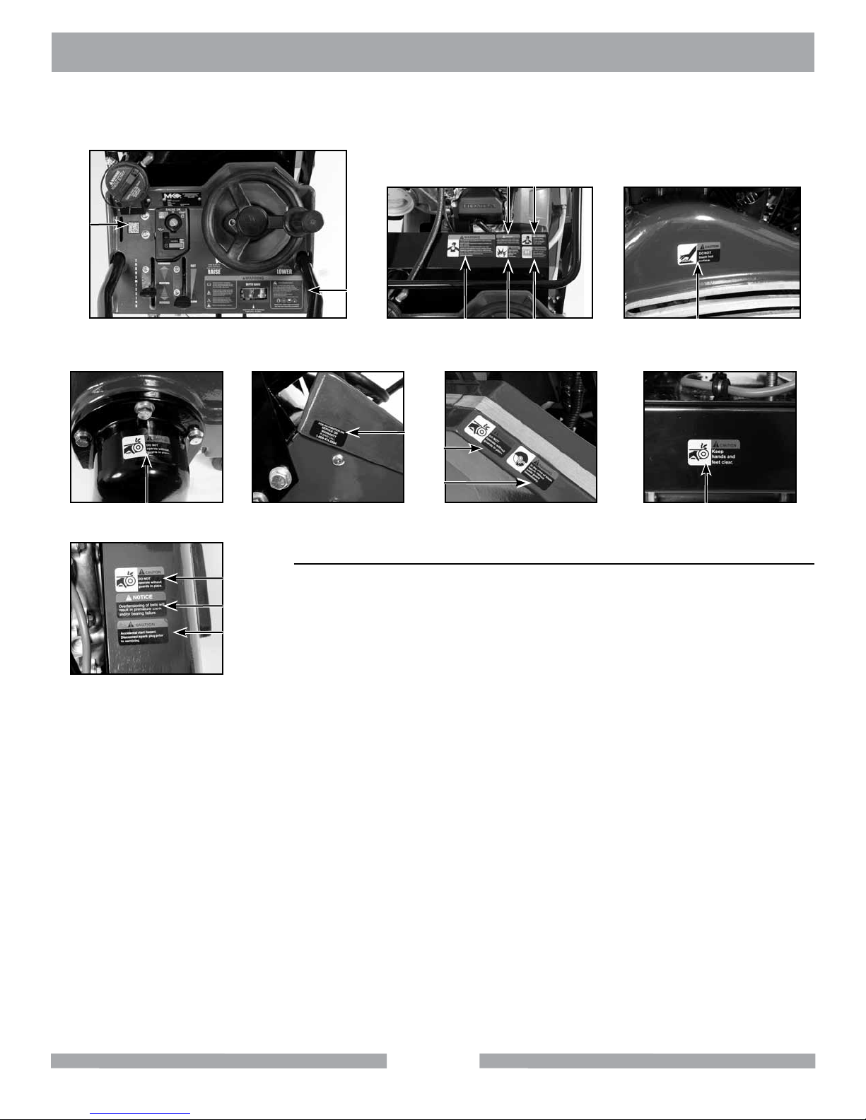
MK-20 SERIES SAFETY
Locations of Safety Decals for models: MK-2020SSP, MK-2024HSP, and MK-2020HSP
K M
L
N
BH IA
E
C
D
C
Location Description
A
C
G
J
Gas Tank - Top Warning - Silica
B
Gas Tank - Top Read Manual
C
Shaft Cover/Belt Guard/Blade Guard Guards in Place
D
Blade Guard - Top Replace Blade Guard
E
Frame - Side Service
F
Frame - Front Hand & Feet Clear
G
Belt Guard - Front Overtensioning Belts
H
Gas Tank - Top Refueling
I
Belt Guard Hot Surface
J
Belt Guard Accidental Start
K
Gas Tank - Top Exhaust/Cancer
L
Console QR Code for Manuals
M
Gas Tank - Top Lethal Exhaust
N
Console Machinery Hazard
F
11

MK-20 SERIES
PRODUCT SPECIFICATION
PRODUCT SPECIFICATIONS
The MK-20 Series is a versatile gas powered Concrete Saw. Operated and used according to this
manual, the MK-20 Series will provide years of dependable service.
General Description
The MK-20 Series is engineered as a portable concrete saw powered by a Honda, Kohler or
Vanguard gas engine. The saw is capable of 6-5/8” depth of cut with an 18” blade and 7-5/8” depth of
cut with a 20” blade.
Motor and Weight Specications
Motor and Weight specications for the MK-20 Series are listed below.
Model
Engine Honda (Gas) Vanguard (Gas) Kohler (Gas) Honda (Gas)
Power GX390 V-Twin CH440 GX390
Starter Pull Pull Pull Pull
Fuel Capacity 1.6 Gallons 1.6 Gallons 1.6 Gallons 1.6 Gallons
Blade Capacity 18” 18” 18” 18”
Blade RPM 3,400 3,400 3,400 3,400
Depth of Cut 6-5/8” (167 mm) 6-5/8” (167 mm) 6-5/8” (167 mm) 6-5/8” (167 mm)
Weight 310 lbs. (141 kg) 310 lbs. (141 kg) 310 lbs. (141 kg) 290 lbs. (132 kg)
Part # 156499 169949 168798 155714
Model
Engine Honda (Gas) Honda (Gas)
Power GX630 GX360
Starter Electric Electric
Fuel Capacity 1.6 Gallons 1.6 Gallons
Blade Capacity 20” 20”
Blade RPM 2,863 2,863
Depth of Cut 7-5/8” (194 mm) 7-5/8” (194 mm)
Weight 392 lbs. (178 kgs) 398 lbs. (181 kg)
Part # 156498 158777
MK2013HSP MK-2013VSP MK2014K MK2013HE
MK-2020HSP MK-2024HSP
Blade
The MK-20 Series uses a 18” to 20” diameter diamond blade.
Concrete Saw Usage
The MK-20 Series is designed to cut various grades of concrete surfaces.
12
MK-20 SERIES UNPACKING
MK-20 Series Series Features
• One-piece box construction chassis made from 3/16” hot-rolled steel
• Powder-coated chassis resists peeling and corrosion
• Cast-aluminum hinged blade guard
• Stainless steel water distribution system supplies water to both sides of blade
• Blade guard mounts on both left- or right-hand side of saw and cuts within 2” of wall or curb
• Heavy-duty blade shaft supported by two 1-3/16”, self-aligning pillow blockbearings
• Depth control assembly engineered for smooth, controlled blade insertion
• Built-in tach/hour meter
• Depth feed gauge indicator
• Heavy-duty hydro static transmission with variable speed drive
• Durable 8” x 2-1/4” non-slip rubber wheels with maintenance-free hubs & roller bearings
• Forward travel speed: 0-80’ minute
UNPACKING
Your saw has been shipped from the factory thoroughly inspected. Only minimal assembly and
service is required. Check each item, making certain all items are accounted for and in good visual
condition before discarding any packing materials. If there are any missing or damaged parts call MK
Diamond Customer Service at 800-421-5830.
WARNING
Never start engine until all initial servicing and set up steps are completed according to this operations manual and engine manual. Read and familiarize yourself
with all controls and features of the saw before beginning operations.
Remove the saw from the pallet and place it on a at surface. Two people are required to lift saw.
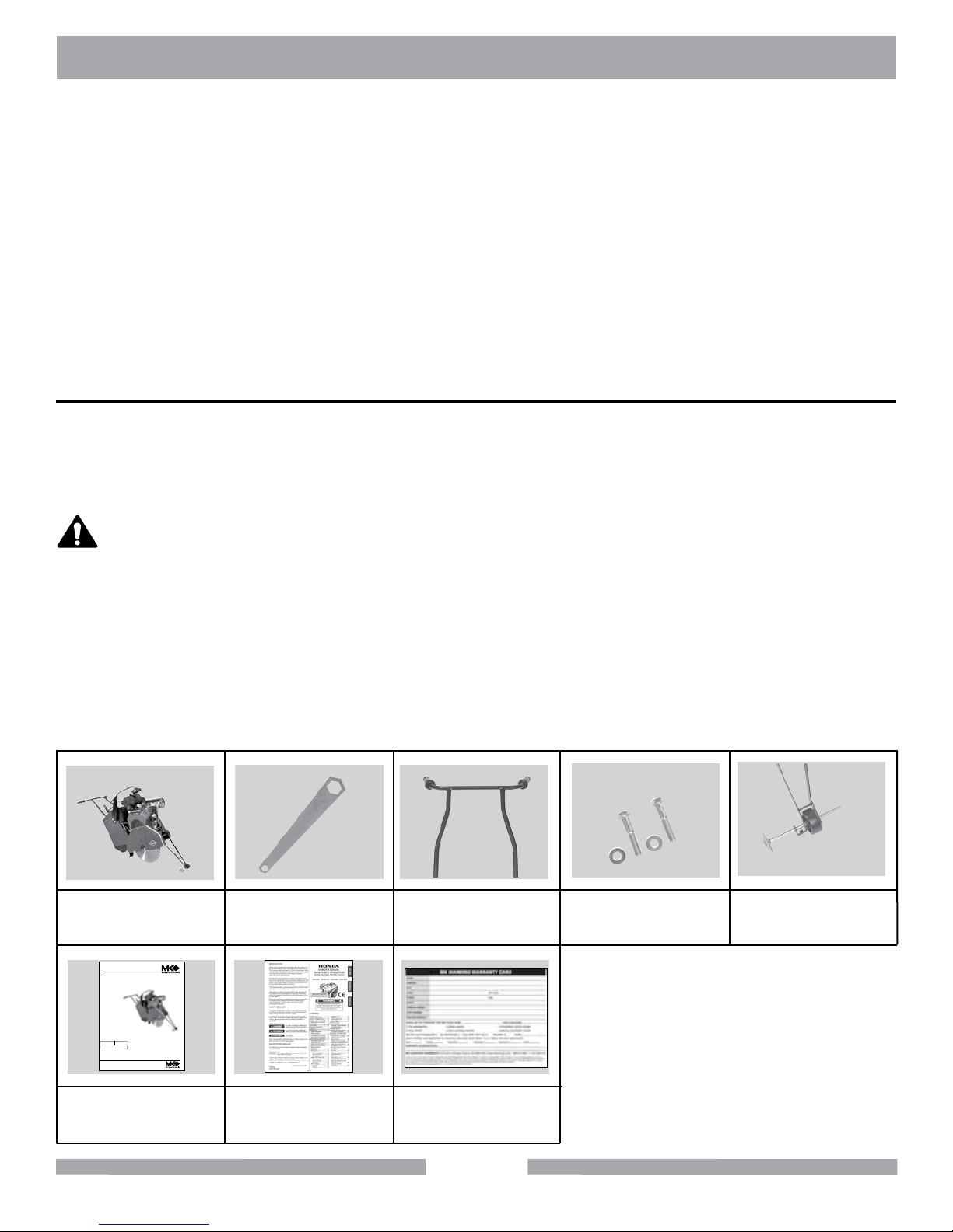
CONTENTS
In the containers, you will nd one (1) MK-20 Series Saw, one (1) Blade Nut Wrench, one (1) Handlebar, two (2) Handlebar Bolts and Washers, one (1) Pointer, one (1) MK-20 Series Owner’s Manual,
one (1) Engine Owners Manual, one (1) Warranty Card.
MK-20 Series
Saw
www.mkdiamond.com
Gas Powered
Concrete Saw
MK-20 SERIES
OWNER’S MANUAL &
OPERATING INSTRUCTIONS
1 Blade Nut
Wrench
Handlebar
Handlebar
Bolts and Washers
Pointer
03.2012
Revision 201
Manual Part# 156777
Caution: Read all safety and operating instructions
before using this equipment. This owner’s manual
MUST accompany the equipment at all times.
MK-20 Series
Engine Manual Warranty
Owner’s Manual
Card
13
MK-20 SERIES TRANSPORT
TRANSPORT
CAUTION
1. The MK-20 Series weighs approximately two hundred and thirty-ve (235
pounds), use care when transporting.
2. Two people are required to lift and transport the MK-20 Series.
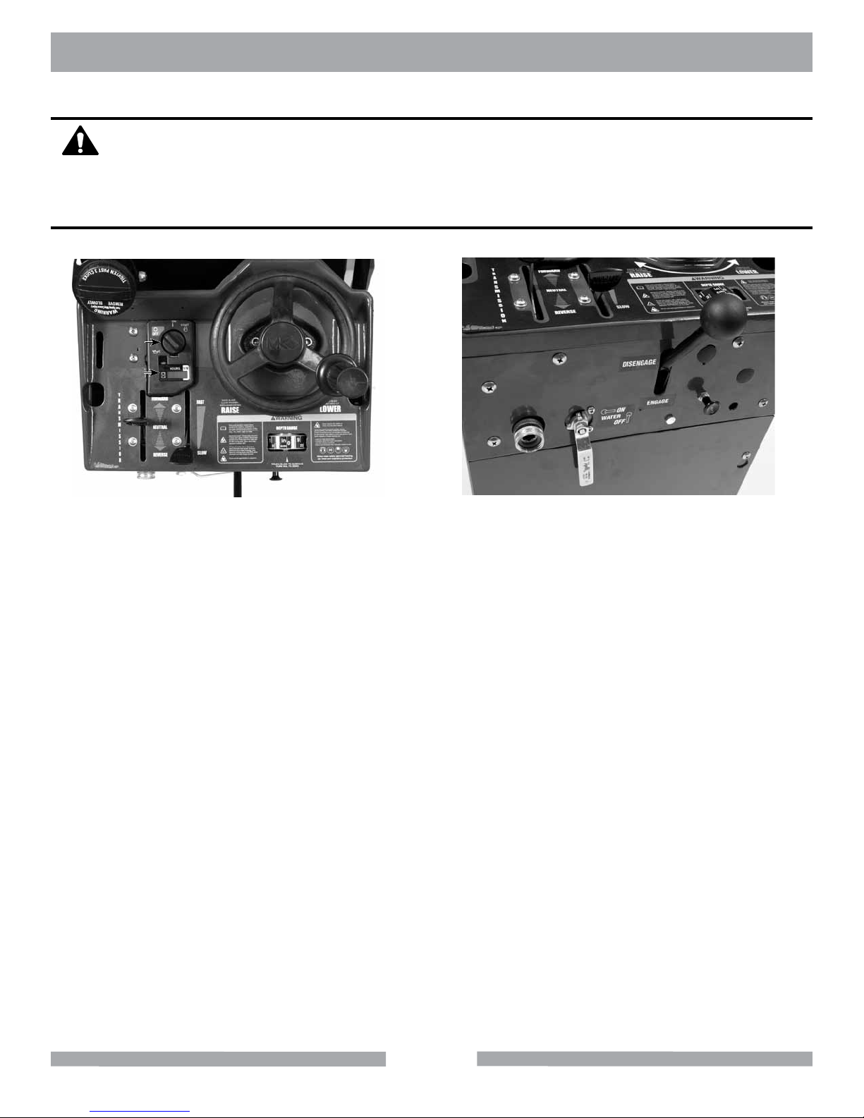
DESCRIPTION OF CONTROLS
1
2
3
7
4
5
6
8
9
10
1. The Depth Control Wheel raises the blade when rotated clockwise, and lowers the blade
when rotated counterclockwise.
2. The keyed ignition switch turns clockwise to the on and start positions. The engine turns
over with the switch in the start position. Release the key after the engine starts.
3. When the engine is running, the Tach/Hour Meter display will indicate the engines RPM.
When the engine is shut off, the display will switch to run time, initially in minutes, and
then switching to hours after the rst hour of operation.
4. The Transmission Speed Lever moves the saw forward by pushing the lever away from
the operator and moves the saw in reverse by pulling the lever toward the operator.
Always place this control in central neutral position before using the engage/disengage
lever or starting or stopping the engine.
5. The Throttle control increases engine rpm from slow (idle) at the bottom, to fast
(full rpm) at the top.
6. Depth Gauge should be adjusted to zero when setting up the saw.
7. Use water hose bibb for wetting cutting. After connecting hose, turn on the water at the
source and use Water Control Lever to control ow of water to the blade. Be sure that
both sides of the blade are getting adequate ow of water.
8. Water Control Lever is off in the vertical position and fully on in the horizontal position. It
may be placed at in between settings to regulate the water ow.
9. The Transmission Engage/Disengage Lever is engaged in the full down position.
10. The Choke is located on the back panel for convenient cold starting.
14
MK-20 SERIES ASSEMBLY
Follow the assembly instructions to prepare your saw for operation.
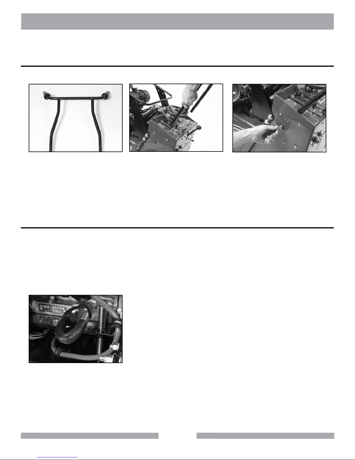
HANDLEBAR ASSEMBLY
(A)
Locate the threaded holes on
both sides of the handlebar.
FILLING OIL RESERVOIR
NOTE:
The engine is shipped with no oil in the crankcase. Refer to the engine manual for details on the type and amount of oil required.
To ll the crankcase with oil, place the engine level. In order for this to be accomplished
the blade must not be installed, and the depth adjustment must be down (until the engine is level).
(B)
Align the handlebar with the
holes on both sides of the frame at
the desired height.
NOTE:
The engine and oil must be warm and your saw must
be on level ground to get an accurate oil level reading.
(C)
Install one Washer onto each bolt.
Install bolt through the Handlebar
and into the holes and tighten.
(A)
Verify the Oil Drain Cap is installed
onto the Oil Drain Line and is tight.
Refer to Engine Manual for details.
15
MK-20 SERIES ASSEMBLY
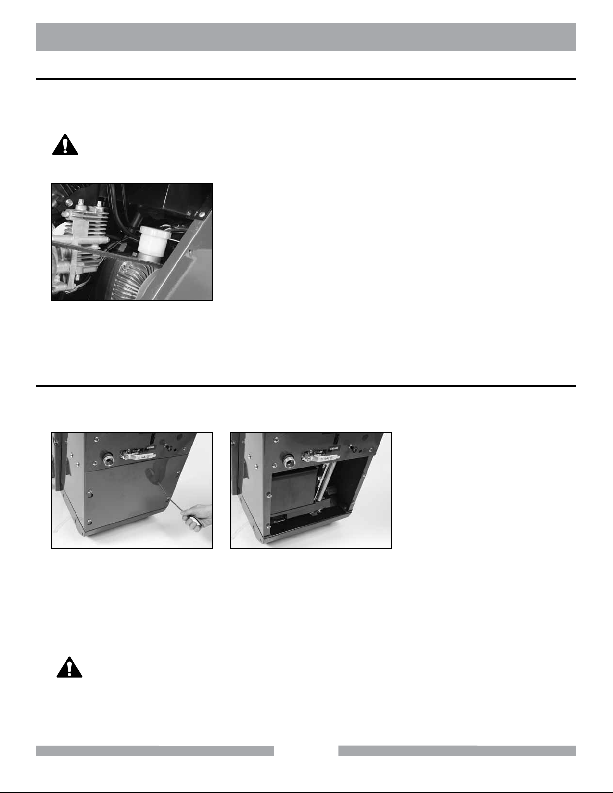
HYDRO-STATIC TRANSMISSION
The Hydro-Static Transmission is factory lled with uid having a viscosity equivalent to SAE 20 W
20.
Do not overll the expansion tank. Notice that the full level line is near the
NOTICE
(A)
Check the oil level on the expansion
tank to ensure that the transmission
has adequate uid.
bottom of the expansion tank. Over lling will result in rupturing the seals
on the hydromatic transmission and subsequent mechanical damage.
BATTERY PREPARATION
The 12 volt battery is shipped wet and charged. Connect the battery leads according to the following
steps to ensure that power is provided to the engines electric starter.
(A)
Remove the front tower panel to ob-
tain access to the battery terminals.
Connect the positive (+) battery
cable to the positive battery terminal.
Connect the negative battery cable
to the negative terminal. Tighten
the cap screws and nuts securely
to assure proper electrical contact.
(B)
Replace panel.
When tightening the positive (+) battery cable end, do not contact the nega-
WARNING
tive (-) battery terminal with the wrench or other metallic objects. This could
cause an electrical short and electrical sparking or an explosion of the battery.
Be careful not to connect the battery in reverse polarity, as this will short circuit
the battery charging system causing the fuse on the engine to become damaged, and also possibly resulting in an explosion of the battery.
16
MK-20 SERIES ASSEMBLY
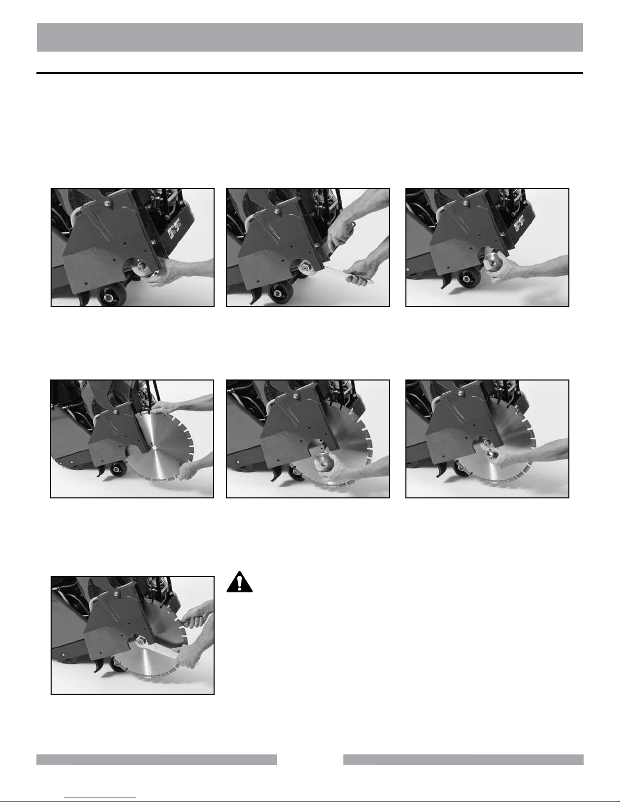
DIAMOND BLADE INSTALLATION
NOTE:
1. When installing the blade retaining-bolt, ensure the threads of the bolt are
aligned with the threads of the drive shaft so as not to “cross-thread” the bolt.
2. When installing the blade ensure that the blade shaft and anges are free from dirt
and all foreign material before mounting blade on the blade shaft. Tightening a blade
against an uneven surface can cause fracture or cause the blade to run out of alignment.
3. Blade shaft threads are left-handed on the right side of the saw and right-hand on the
left of the saw.
(A)
Open the Blade Guard Cover.
Locate the Blade Shaft Nut and the
Outer Flange.
(B)
Loosen the Blade Shaft Nut while
holding the Shaft Wrench steady.
(C)
Remove the Blade Nut and Outer
Flange.
(D)
Install the Diamond Blade onto the
Blade Shaft and Drive Pin. Ensure
directional arrow on the blade indi-
cates proper rotational direction.
(G)
Tighten Blade Shaft Nut holding
the Blade Shaft steady. Lower and
close Blade Guard.
(E)
Install the Outer Flange. Verify the
drive pin is seated; it must project
through the hole in the blade and into
the ange.
WARNING
Do not operate the saw without the proper
Blade Guard covering. Ensure that the blade
exposure does not exceed 180 degrees during
operation.
DO NOT use woodcutting, or carbide blades
on this machine! Use ONLY Diamond
blades on machine.
NOTE:
Raise the blade as high as possible when maneuvering so that the blade will not strike the
pavement. The blade is spinning whenever the
saw is running.
17
(F)
Install the Blade Shaft Nut.
MK-20 SERIES SET-UP
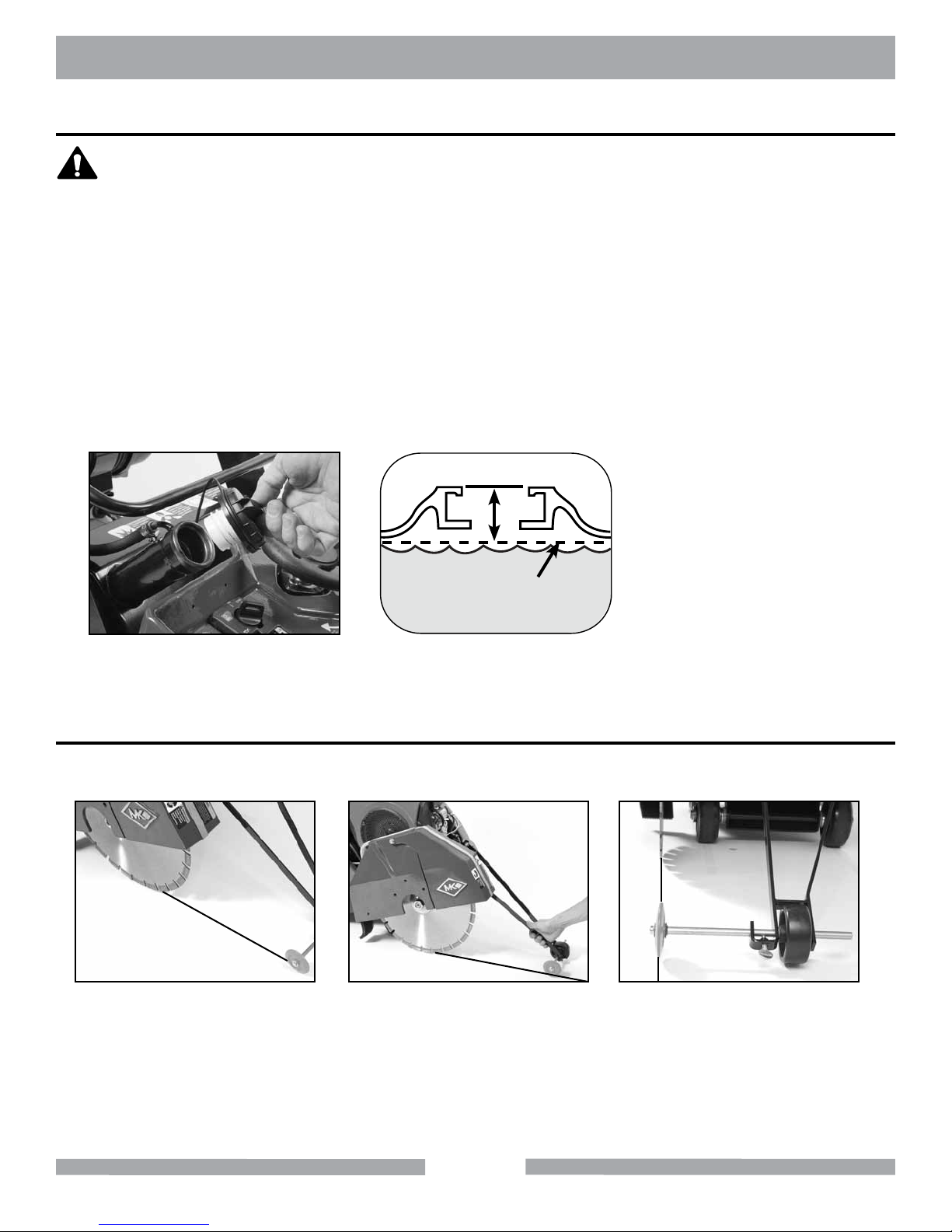
FILLING FUEL TANK
WARNING
NOTE:
1. Gasoline is highly ammable and explosive. You can be burned or seriously
injured when handling fuel.
2. To fuel, stop engine if running, and allow it to cool.
3. Fuel in a well-ventilated area.
4. Keep gasoline away from appliance pilot lights, barbeques, electric appliances,
power tools, etc.
5. Wipe up spills immediately. Do not start engine until spill is dry.
6. When lling the fuel tank do not overll. Always leave enough area for
expansion due to environmental heating.
1. Fuel can damage paint and plastic. Be careful not to spill fuel when lling the
fuel tank. Damage caused by spilled fuel IS NOT covered under the warranty.
2. DO NOT use stale or contaminated gasoline, or an oil/gasoline mixture.
1 inch (25mm)
from throat
Maximum Fuel
Level
(A)
Remove the Fuel Cap.
Ensure fuel level is 1” below the
throat of the Fuel Tank.
(B)
FRONT POINTER ALIGNMENT
The Front Pointer is set in line at the factory. However, the pointer should be checked for proper
alignment with the blade after every use.
(A)
Using a straight edge, care-
fully mark a line 12 feet long on
a smooth level concrete surface.
Place Saw parallel to line; lower
Blade and center it over the line.
With the Blade centered over the
line and the Saw Frame parallel
to the line, lower the front Pointer
assembly and position the pointer
(B)
over the line.
(C)
Adjust the Pointer in or out if the
orange wheel is off the line by loosening the thumbscrew on the end of
pointer. Align orange wheel with line
and tighten thumbscrew. Roll saw
along the entire length of the line to
ensure proper alignment.
18
 Loading...