

Page 1
www.mkdiamond.com
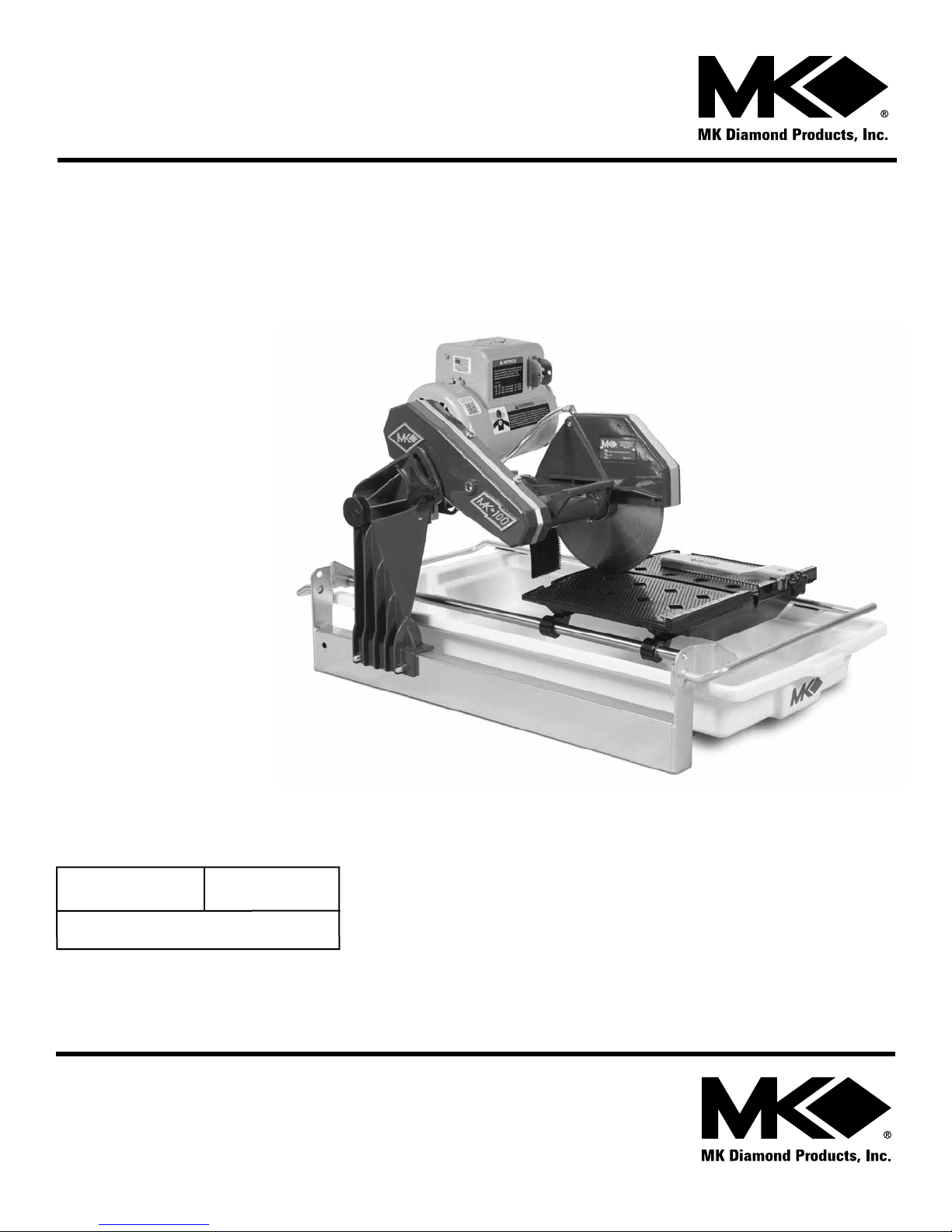
MK-100 TILE SAW
OWNER'S MANUAL
PARTS LIST &
OPERATING INSTRUCTIONS
Revision 105
Manual Part# 158192
Caution: Read all safety and operating instructions
before using this equipment. This parts list MUST
accompany the equipment at all times.
01.2015
Page 2
INTRODUCTION
Congratulations on your purchase of a MK-100 Tile Saw. We are certain that you will be pleased
with your purchase. MK Diamond takes pride in producing the nest construction power tools and
diamond blades in the industry.
Operated correctly, your MK-100 Tile Saw should provide you with years of service. In order to help
you, we have included this manual. This owners manual contains information necessary to operate
and maintain your MK-100 Tile Saw safely and correctly. Please take the time to familiarize yourself
with the MK-100 Tile Saw by reading and reviewing this manual.
Read and follow all safety, operating and maintenance instructions.
If you should have questions concerning your MK-100 Tile Saw, please feel free to call our friendly
customer service department at: 800 421-5830
Regards,
MK Diamond
NOTE THIS INFORMATION FOR FUTURE USE:
MODEL NUMBER:
SERIAL NUMBER:
PURCHASE PLACE:
PURCHASE DATE:
NOTE: For your (1) one year warranty to be effective, complete the warranty card
(including the Serial Number) and mail it in as soon as possible.
2
Page 3

TABLE OF CONTENTS
SAFETY
Safety Messages 4
General Safety Precautions 4-7
California Proposition 65 Message 8
Electrical Requirements 9-12
Safety Label Locations 13
Product Specications 14
UNPACKING, TRANSPORT and ASSEMBLY
Unpacking 15
Contents 15
Transport 16
Stand 17
Assembly 18-19
SETUP, STARTUP, ADJUSTMENT, OPERATION and SHUTDOWN
Setup 20-22
Operation 23-26
Cutting Head Adjustment 27-28
Cleanup 29
MAINTENANCE AND TROUBLESHOOTING
Maintenance 30-35
Troubleshooting 36
EXPLODED VIEW AND PARTS LIST
Exploded View & Parts List 38-45
ACCESSORIES ORDERING and RETURN INSTRUCTIONS
Theory of Diamond Blades 46
Accessories 47
Ordering Information 48
Return Material Policy 48
Packaging Instructions 48
Authorized Service Centers 49
3
Page 4

MK-100 TILE SAW SAFETY
ON
(
(
)
)
ON
(
(
)
)
ON
(
(
)
)
Read and follow all safety, operating and maintenance instructions. Failure to read and follow
these instructions could result in injury or death to you or others. Failure to read and follow these
instructions could also result in damage and/or reduced equipment life. Safety warnings and
guidelines do not by themselves eliminate danger. They are not substitutes for proper accident
prevention procedures and good judgement.
SAFETY MESSAGES
A safety message alerts you to potential hazards that could hurt you or others. Each safety message is
preceded by a safety alert symbol ( ) and one of three words: DANGER, WARNING, or CAUTION.
DANGER You WILL be KILLED or SERIOUSLY INJURED if you DO NOT follow directions.
WARNING
You CAN be KILLED or SERIOUSLY INJURED if you DO NOT follow directions.
You CAN be INJURED if you DO NOT follow directions. It may also be used to
CAUTION
alert against unsafe practices.
DAMAGE PREVENTION AND INFORMATION MESSAGES
A Damage Prevention Message is to inform the user of important information and/or instructions that
could lead to equipment or other property damage if not followed. Information Messages convey
information that pertains to the equipment being used. Each message will be preceded by the word
NOTE, as in the example below.
NOTE:
Equipment and/or property damage may result if these instructions are not followed.
GENERAL SAFETY PRECAUTIONS AND HAzARD SYMBOLS
In order to prevent injury, the following safety precautions and symbols should be followed at all times!
ALWAYS read this Owner’s Manual before operating the machine. DO NOT operate or
service this equipment before reading this entire manual. Read and understand all warnings, instructions and controls on the machine. Know how to stop the equipment quickly in
case of emergency. It is the operators responsibility to use this machine under safe working conditions and conform with federal, state and local codes or regulations pertaining to
safety, air, pollution, noise etc...
ALWAYS keep the Blade and Belt Guards in place. DO NOT operate this machine with any
guard or safety device removed. A Guard, or any damaged part should be repaired or
replaced immediately.
NEVER operate this equipment without proper protective clothing, shatterproof
glasses, steel-toed boots and other protective devices required by the job. Non-slip
foot wear is recommended.
4
Page 5
MK-100 TILE SAW SAFETY
ON
(
(
)
)
ON
(
(
)
)
ON
(
(
)
)
(
(
)
)
(
(
)
)
ON
(
(
)
)
PERSONAL PROTECTIVE EQUIPMENT
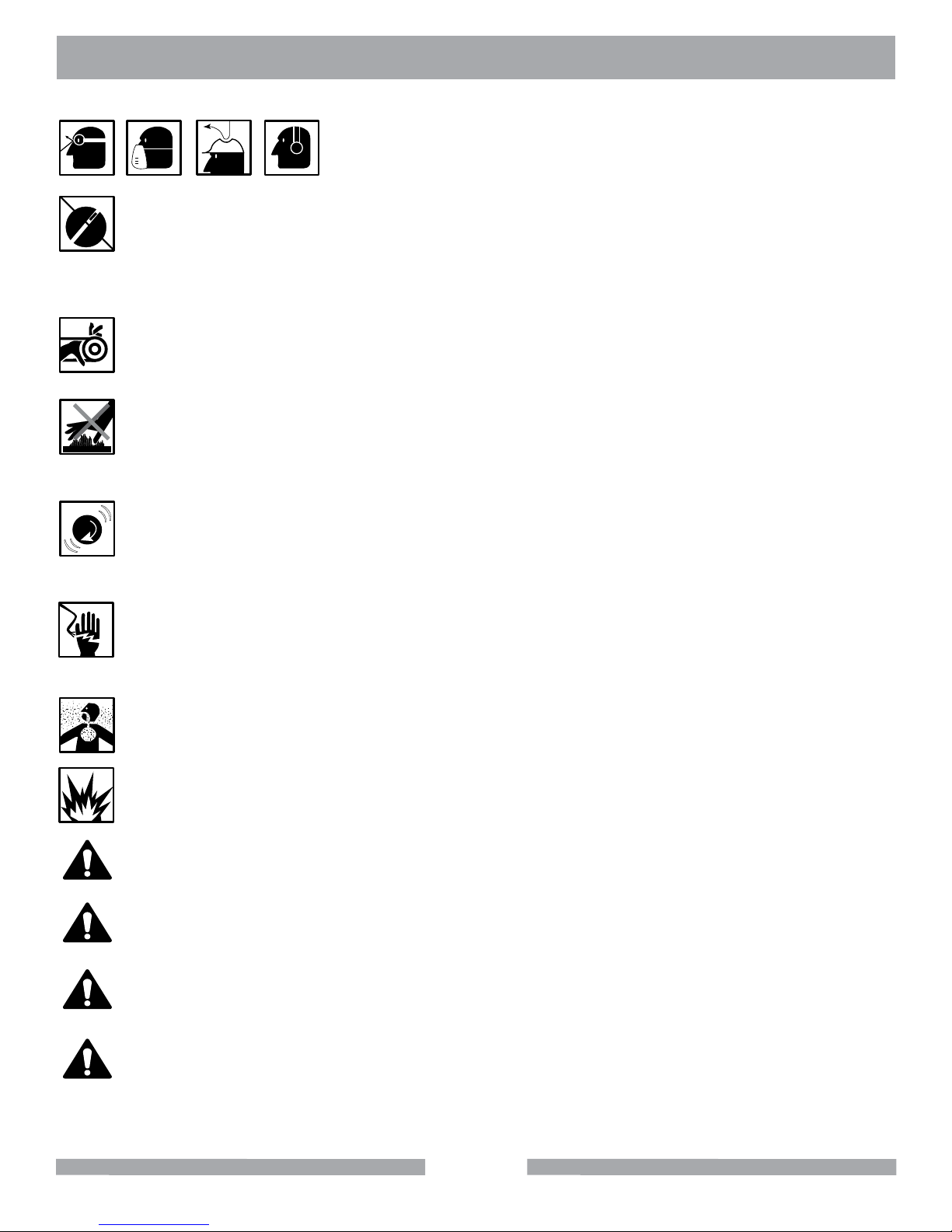
ALWAYS wear approved respiratory, head, ear and eye protection
when operating this machine.
ON
ACCIDENTAL STARTS!
Before starting the engine/motor, be sure the ON/OFF switch is in the OFF position to prevent accidental starting. Place the ON/OFF switch in the OFF position before performing any
service operation. ALWAYS place the power ON/OFF switch in the OFF position when the
machine is not in use.
ROTATING PARTS
Keep hands, feet, hair, and clothing away from all moving parts to prevent injury. Never operate the motor with covers, shrouds, or guards, removed.
HOT PARTS!
Engine components can become extremely hot from operation. To prevent severe burns,
do not touch these areas while the engine is running, or immediately after it is turned off.
Never operate the engine with heat shields removed.
OVER SPEED
)
)
(
(
NEVER tamper with the governor components or settings to increase the maximum speed.
Severe personal injury and damage to the engine or equipment can result if operated at
speeds above maximum.
ELECTRICAL SHOCK
NEVER touch electrical wires or components while the engine is running. Exposed, frayed or
worn electrical wiring and plugs can be sources of electrical shock which could cause severe
injury or burns. Do not touch the plug with wet hands.
ALWAYS avoid inhalation of and skin contact with silica dust and/or mist. Provide proper
dust removal. Use dust-collection system when applicable.
NEVER operate the machine in an explosive atmosphere or near combustible materials.
Sparks from the cutting-action of this machine can ignite flammable materials, liquids, gases
or dust.
This equipment should not be operated by persons under 18 years of age.
KEEP CHILDREN AWAY
All visitors and children should be kept a safe distance from work area. Maintain a safe
operating distance to other personnel.
MAKE THE WORKSHOP KID PROOF
Make the workshops kid proof by using padlocks, master switches or by removing starter keys.
DO NOT FORCE THE TOOL
A power tool will do a job better and safer operating at the rate for which it was designed.
DO NOT force a tool or an attachment to do a job that it was not designed to do.
5
Page 6
MK-100 TILE SAW SAFETY
ON
(
(
)
)
ON
(
(
)
)
ON
(
(
)
)
ON
(
(
)
)
ON
(
(
)
)
ON
(
(
)
)
ON
(
(
)
)
ON
(
(
)
)
ON
(
(
)
)
ON
(
(
)
)
ON
(
(
)
)
ON
(
(
)
)
USE PROPER APPAREL
DO NOT wear loose clothing, gloves, neckties, rings, bracelets, or other jewelry that may
be caught in moving parts. Non-slip footwear is recommended. Wear protective hair covering to contain long hair.
SECURE WORK
Clamps or a vise should be used to hold work whenever practical. Keeping your hands free
to operate a power tool is safer.
DO NOT OVERREACH
Keep proper footing and balance at all times by not overreaching.
DISCONNECT TOOLS
Power tools should always be disconnected before servicing, adjusting or when changing
accessories, such as blades, bits, cutters, and the like.
MAINTAIN TOOLS WITH CARE
Keep tools clean and maintained for the best and safest performance. Always follow
maintenance instructions and examine the machine before use. If any abnormal vibrations
or noises occurs, turn off machine immediately and have the problem corrected before
further use.
REMOVE ADJUSTING KEYS AND WRENCHES
Form a habit of checking to see that keys and adjusting wrenches are removed from
the power tool before it is turned on.
KEEP WORK AREA CLEAN
Cluttered work areas and benches invite accidents. Keep area around machine clear of
obstructions which could cause persons to fall.
DO NOT USE IN DANGEROUS PLACES
DO NOT operate equipment in dangerous or hazardous environments. DO NOT use power
tools in damp or wet locations nor expose them to rain. Always keep the work area well
lighted.
USE RECOMMENDED ACCESSORIES
Consult the owner’s manual for recommended accessories. Using improper accessories
may increase the risk of personal or by-stander injury. Unauthorized equipment
modifications will void all warranties. Manufacturer does not assume responsibility for any
accident due to equipment modifications.
ALWAYS ensure that the machine is on level ground before using.
NEVER STAND ON THE TOOL
Serious injury could occur if a power tool is tipped, or if a cutting tool is unintentionally
contacted.
TRANSPORT
When loading or unloading the machine, use caution. Remove the blade prior to hoisting,
loading and transporting the machine.
6
Page 7
MK-100 TILE SAW SAFETY
ON
(
(
)
)
ON
(
(
)
)
ON
(
(
)
)
ON
(
(
)
)
ON
(
(
)
)
ON
(
(
)
)
ON
(
(
)
)
ON
(
(
)
)
ON
(
(
)
)
ON
(
(
)
)
ON
(
(
)
)
ON
(
(
)
)
CHECK FOR DAMAGED PARTS
Before using a power tool, check for damaged parts. A guard or any other part that is
damaged should be carefully checked to determine if it would operate properly and
perform its intended function. Always check moving parts for proper alignment or binding.
Check for broken parts and mountings and all other conditions that may affect the
operation of the power tool. A guard, or any damaged part, should be properly repaired or
replaced. Always check the machine for loose bolts before starting.
DIRECTION OF ROTATION
A blade or cutter should always be installed so that rotation is in the direction of the
arrow imprinted on the side of the blade or cutter. It should correspond with the rotational
direction of the motor. Always feed work into a blade against the direction of rotation.
NEVER LEAVE A TOOL UNATTENDED
TURN POWER OFF - Do not leave a tool until it comes to a complete stop. ALWAYS
turn a power tool OFF when leaving the work area, or, when a cut is finished.
NEVER disconnect any "emergency or safety devices". These devices are intended for
operator safety. Disconnection of these devices can cause severe injury, bodily harm, or
even death! Disconnection of any of these devices will void all warranties. Unauthorized
equipment modifications will void all warranties. Manufacturer does not assume
responsibility for any accident due to equipment modifications.
NEVER use this machine with any cutter designed for woodworking.
NEVER operate this equipment when not feeling well due to fatigue, illness or taking medicine.
NEVER operate this equipment under the influence of drugs or alcohol.
On belt driven equipment, overtensioning of belts will result in premature crank and/or bearing
failure.
Whenever necessary, replace nameplate, operation and safety decals when they become
difcult to read.
ALWAYS store equipment properly when it is not being used. Equipment should be stored in
a clean, dry location out of the reach of children
DO NOT lend or rent this equipment without including the Owner's Manual and the Engine/
Motor Manufacturer's Manual.
Check the chemical properties of the material to be cut/grinded and follow all EPA/OSHA
Regulations.
7
Page 8
ON
(
(
)
)
MK-100 TILE SAW SAFETY
SILICA DUST WARNING
Grinding/cutting/drilling of masonry, concrete, metal and other materials with silica in their composition
may give off dust or mists containing crystalline silica. Silica is a basic component of sand, quartz,
brick clay, granite and numerous other minerals and rocks. Repeated and/or substantial inhalation of
airborne crystalline silica can cause serious or fatal respiratory diseases, including silicosis. In addition, California and some other authorities have listed respirable crystalline silica as a substance
known to cause cancer. When cutting such materials, always follow respiratory precautions.
Use appropriate NIOSH-approved respiratory protection where dust hazard may occur. Paper masks
or surgical masks without a NIOSH approval number are not recommended because they do little to
protect the worker. For more information about respirator programs, including what respirators have
received NIOSH approval as safe and effective, please visit the NIOSH website at:
http://www.cdc.gov/niosh/topics/respirators
Observe OSHA regulations for respirator use (29 C.F.R.§1910.134).
Visit http://www.osha.gov for more information.
CALIFORNIA PROPOSITION 65 MESSAGE
Some dust created by power sanding, sawing, grinding, drilling, and other construction activities contain chemicals known (to the State of California) to cause cancer, birth defects or other reproductive
harm. Some examples of these chemicals are:
• Lead, from lead-based paints
• Crystalline silica from bricks, cement and other masonry products
• Arsenic and chromium, from chemically treated lumber
For further information, consult the following sources:
http://www.osha.gov/dsg/topics/silicacrystalline/index.html
http://www.cdc.gov/niosh/docs/96-112/
http://oehha.ca.gov/prop65/law/P65law72003.html
http://www.dir.ca.gov/Title8/sub4.html
Your risk from these exposures varies depending on how often you do this type of work. To reduce
your exposure to these chemicals, work in a well-ventilated area, and work with approved safety
equipment, such as dust masks that are specially designed to lter out microscopic particles. Where
use of a dust extraction device is possible, it should be used. To achieve a high level of dust collection, use an industrial
HEPA vacuum cleaner. Observe OSHA 29 CFR part 1926.57 and 1926.103.
WARNING
Sawing, grinding and drilling generate dust. Excessive airborne particles may cause irritation to eyes, skin and respiratory
tract. To avoid breathing impairment, always employ dust controls and protection suitable to the material being sawed or
drilled; See OSHA (29 CFR Part 1910.1200).
8
Page 9
ON
(
(
)
)
MK-100 TILE SAW SAFETY
ELECTRICAL REQUIREMENTS AND GROUNDING INSTRUCTIONS
In order to prevent electrical shock and injury, the following electrical safety precautions and symbols
should be followed at all times!
WARNING
In case of a malfunction or breakdown, grounding provides a path of least resistance for electrical
current to reduce the risk of electric shock. This tool is equipped with an electric cord which has an
equipment-grounding conductor and a grounding plug. The plug must be plugged into a matching
outlet that is properly installed and grounded in accordance with all local codes and ordinances.
• DO NOT modify the plug provided - if it will not t the outlet, have the proper outlet
installed by a qualied electrician.
• Improper connections of the equipment-grounding conductor can result in a risk of electric
shock. The equipment-grounding conductor is the insulated conductor that has an outer
surface that is green, with or without yellow stripes. If repair or replacement of the electric
cord or plug is necessary, DO NOT connect the equipment-grounding conductor to a live
terminal.
• Check with a qualied electrician or service personnel if the grounding instructions are not
completely understood, or if in doubt as to whether the tool is properly grounded.
• Use only 3-wire extension cords that have 3-prong grounding plugs and 3-pole receptacles
that accept the tool’s plug.
• Repair or replace a damaged or worn cord immediately.
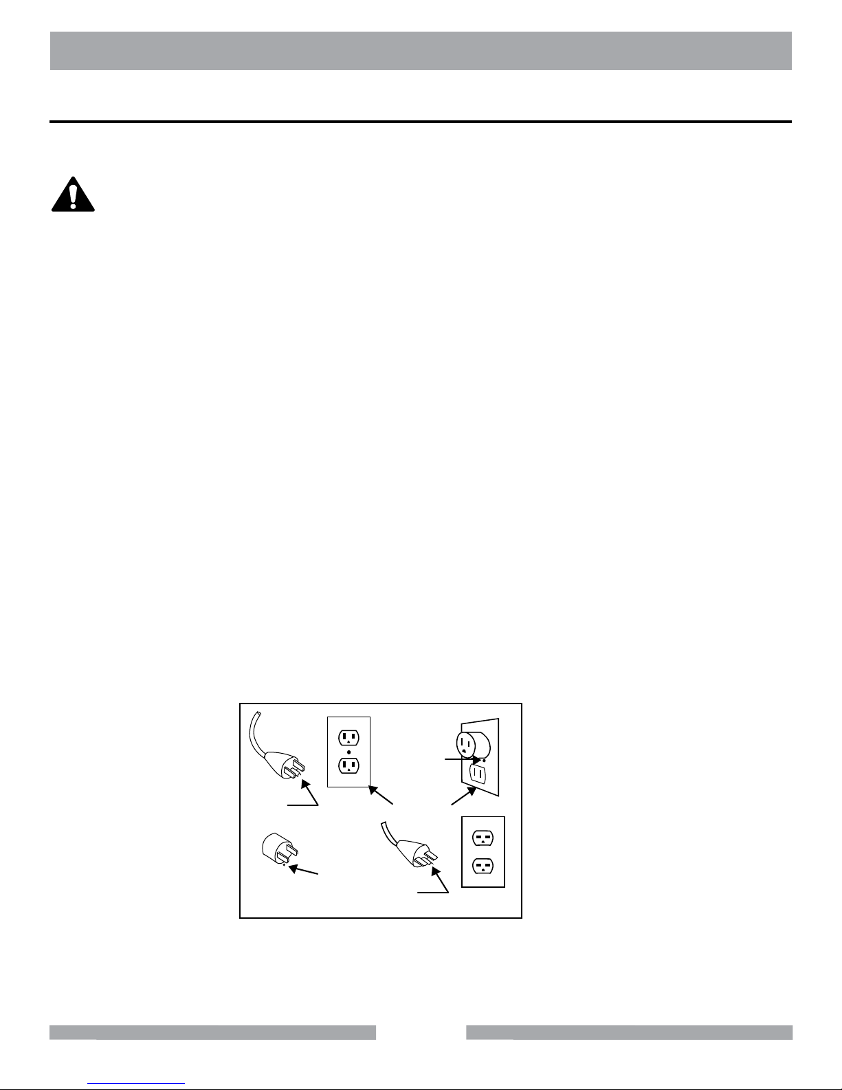
This tool is intended for use on a circuit that has an outlet that looks like the one shown in Sketch A.
The tool has a grounding plug that looks like the plug illustrated in Sketch A. A temporary adapter,
which looks like the adapter illustrated in sketches B and C, may be used to connect this plug to a
2-pole receptacle as shown in Sketch B, if a properly grounded outlet is not available. The temporary
adapter should be used only until a properly grounded outlet can be installed by a qualied electrician. The green-colored rigid ear, plug, and the like, extending from the adapter, must be connected
to a permanent ground, such as a properly grounded outlet box.
Metal Screw
Grounding
Pin
(A)
ADAPTER
Grounding
Means
(C)
Cover of
Grounded
Outlet Box
Grounding
Pin
(B)
(D)
Circuit and Adapter Information
Use of a temporary adapter is not permitted in Canada.NOTE:
NOTE:
If permanently connected this tool should be connected to a grounded metal permanent
wiring system; or to a system having an equipment - grounding conductor.
9
Page 10
MK-100 TILE SAW SAFETY
ON
(
(
)
)
ON
(
(
)
)
ON
(
(
)
)
ON
(
(
)
)
ON
(
(
)
)
ELECTRIC MOTOR SAFETY
For maintenance care and operation of the electric motor, refer to your electric motor instruction booklet furnished with the electric motor. Protect the electric motor from dust as much as possible and keep
ventilating openings clean. Before plugging in the machine, make sure that the outlet voltage is within
the voltage marked on the machines's data plate.
CAUTION
DO NOT spray water on the electric motor. DO NOT touch the plug with wet hands. To reduce
the risk of electrocution, keep all connections dry and off the ground.
DO NOT operate electric motor in an explosive environment.
DO NOT EXPOSE TO RAIN
DO NOT expose to rain or use in damp locations.
WARNING
If operating the equipment in damp locations is unavoidable, ALWAYS use a Ground Fault
Circuit Interrupter, ALWAYS wear rubber gloves and footwear in damp conditions.
DO NOT abuse the cord. Never use the cord to carry the equipment or to pull the plug from
the outlet. Keep the cord away from heat, sharp edges, and moving parts. Replace damaged cords immediately. Damaged cords increase the risk of electric shock.
WARNING
To reduce the risk of electrocution, keep all connections dry and off the ground. A Ground Fault
Circuit Interrupter (GFCI) should be provided on the circuit(s) or outlet(s) to be used for this
machine. Receptacles are available having built-in GFCI protections and may be used for this
measure of safety. When using an extension cord, GFCI should be installed closest to the power
source, followed by the extension cord and lastly, the machine.
WARNING
The water pump requires a GFCI. To reduce risk of electrical shock when operating the machine
with the pump plugged into the 3-pole receptacle on the motor, connect the machine to a GFCI
outlet. See the pump manual and informational tags enclosed separately for all pump information.
10
Page 11
MK-100 TILE SAW SAFETY
Surface
ON
(
(
)
)
ON
(
(
)
)
WARNING
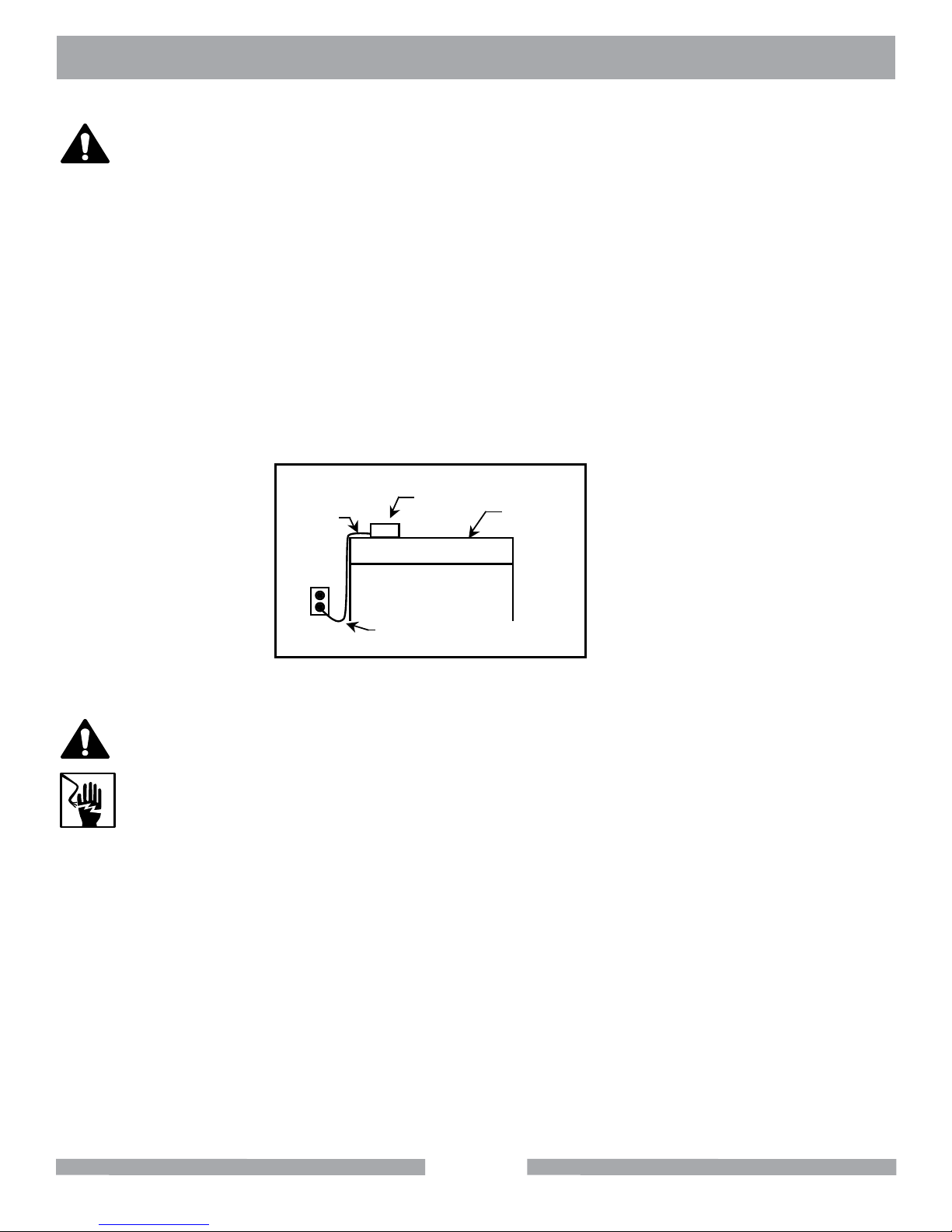
To avoid the possibility of the appliance or plug receptacle getting wet, position the machine to one
side of a wall mounted receptacle. This will prevent water from dripping into the receptacle or plug. A
"drip loop," shown in the picture below, should be arranged by the user to properly position the power
cord relative to the power source. Use the drip loop as a way to prevent GFCI and plug from getting
wet.
The "drip loop" is that part of the cord below the level of the receptacle (or the connector, if an extension cord is used). This method of positioning the cord prevents the travel of water along the power
cord and coming in contact with the receptacle.
If the plug or receptacle gets wet, DO NOT unplug the cord. Disconnect the fuse or circuit breaker
that supplies power to the tool. Then unplug and examine for presence of water in the receptacle.
Power
Cord
Power
Tool
Drip Loop
Supporting
Drip Loop Information
WARNING
Use only extension cords that are intended for outdoor use. These extension cords are
identied by a marking "Acceptable for use with outdoor appliances; store indoors while not
in use." Use only extension cords having an electrical rating not less than the rating of the
product. DO NOT use damaged extension cords. Examine extension cords before using and
replace if damaged. DO NOT abuse extension cords and DO NOT yank on any cord to disconnect. Keep cords away from heat and sharp edges. Always disconnect the extension cord
from the receptacle before disconnecting the product from the extension cord.
ALWAYS make certain that the power source required for the electric motor is correct and always
use the correct NEMA conguration plug. Motors can burn out when the line voltage falls 10% below
the voltage rating of the motor. Failure to use proper voltage will cause the motor to overheat. Make
certain that the correct size grounded (3-wires) extension cord is used.
11
Page 12
MK-100 TILE SAW SAFETY
ON
(
(
)
)
WARNING
Use of undersized extension cords result in low voltage to the motor that can result in motor burnout
and premature failure. MK Diamond warns that equipment returned to us showing signs of being run
in a low voltage condition, through the use of undersized extension cords,will be repaired or replaced
totally at the customer’s expense. There will be no warranty claim.
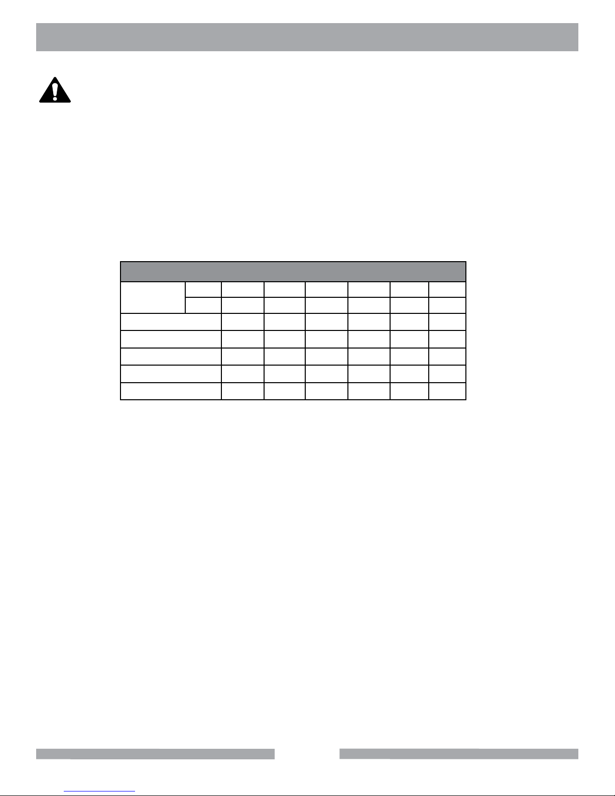
To choose the proper extension cord,
• Locate the length of extension cord needed in the table below.
• Once the proper length is found, move down the column to obtain the correct
AWG size required for that length of extension cord.
EXTENSION CORD LENGTH
Nameplate
Amperes
0 - 5 16 16 16 14 12 12
115V 25' 50' 75' 100' 150' 200'
250V 50' 100' 150' 200' 300' 400'
5.1 - 8 16 16 14 12 10 •
8.1 - 12 14 14 12 10 • •
12.1 - 15 12 12 10 10 • •
15.1 - 20 10 10 10 • • •
12
Page 13
MK-100 TILE SAW SAFETY
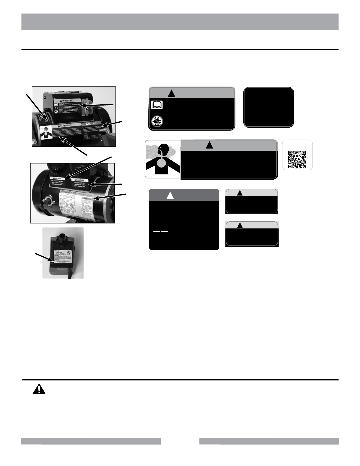
SAFETY LABEL LOCATIONS
Safety labels contain important safety information. Please read the information contained on each
safety label. These labels are considered a permanent part of your saw. If a label comes off or
becomes hard to read, contact MK Diamond or your dealer for a replacement.
D
H
B
E
A
C
!
WARNING
For Your Own Safety Read Instruction Manual
Before Operating Saw.
Wear Eye Protection.
Disconnect Saw Before Servicing, when Changing
Cutting Wheels and Cleaning.
Use Tool Only with Smooth Edge Cutting Wheels
Free of Openings and Grooves.
Replace Damaged Cutting Wheel Before Operating.
Do Not Fill Water Bath Above Water Fill Line.
See Manual for Pump Replacement.
Label A
!
WARNING
Grinding/cutting/drilling of masonry, concrete, metal and other materials with silica in
their composition may give off dust or mists containing crystalline silica. Silica is a basic
component of sand, quartz, brick clay, granite and numerous other minerals and rocks.
Repeated and/or substantial inhalation of airborne crystalline silica can cause serious
or fatal respiratory diseases, including silicosis. In addition,California and some other
authorities have listed respirable crystalline silica as a substance known to cause cancer.
F
G
!
NOTICE
Most Motor Problems are caused by improper
voltage and extension cords. Cord should be
one-piece and short as possible. Cord
selection should match the following table.
1-2 H.P.
115v 230v
100’
150’
250’
Max. Cord Length
Max. Cord Length
Max. Cord Length
Label C
25’
50’
75’
Label B
No. 12 Wire
No. 10 Wire
No. 8 Wire
This saw is to be used
with a Ground Fault
FOR INFORMATION ON
SERVICE OR
WARRANTY
PLEASE CALL
1-800-474-5594
Label D
CAUTION
!
Circuit Interrupter.
Label E
CAUTION
!
Receptacleis for
water pump only.
125V,.6 amps max.
Label F
For manuals and parts
lists scan the QR code
with your smart phone
Label I
Tile Master Label Sheet Part#166012
Decal/Label Location Description
A Motor-Side Warning - Read and Follow Operating Instructions
B Motor - Front Warning - Silica Warning
C Motor - Side Notice - Receptacle is for Water Pump Only
D Motor - Back Service/ Warranty
E Motor - Side Caution - Use with GFCI only
F Motor - Side Caution - Receptacle for water pump
G Motor - Side Motor Specifications
H
I
Water Pump
Motor - Side
Pump Specifications
QR Code - Manuals
TILE SAW SPECIFIC WARNINGS
WARNING
Wear eye protection.
Use splash guard for every operation for which it can be used.
Disconnect saw before servicing, when changing cutting blades, and cleaning.
Replace damaged cutting blade before operating.
13
Page 14
MK-100 TILE SAW PRODUCT SPECIFICATIONS
PRODUCT SPECIFICATIONS
The MK-100 is a versatile Tile Saw. Operated and used according to this manual, the MK-100
will provide years of dependable service.
GENERAL DESCRIPTION
The MK-100 Tile Saw is engineered as a tabletop or stand mounted wet tile saw. The saw
includes a powerful 120V electric motor. The saw is capable of cutting tile up to twenty (20) inches
in length, depth of cut 3".
MOTOR SPECIFICATIONS
Motor specifications for the MK-100 are listed in below.
Voltage 120V
Motor Only Amperage 14.5
Frequency 60Hz
RPM 3400 rpm
Horse Power 1.5 hp
Weight 96 lbs.
BLADE CAPACITY
The MK-100 uses a ten (10) inch (254 mm) diameter, wet cutting continuous rim, MK Diamond
blade with a five-eighths (5/8) inch (15.875 mm) arbor.
TILE TYPES
The MK-100 can cut a variety of tile types including stone, masonry, and lapidary products.
NOTE:
The MK-100 is not designed to cut plastic or metals.
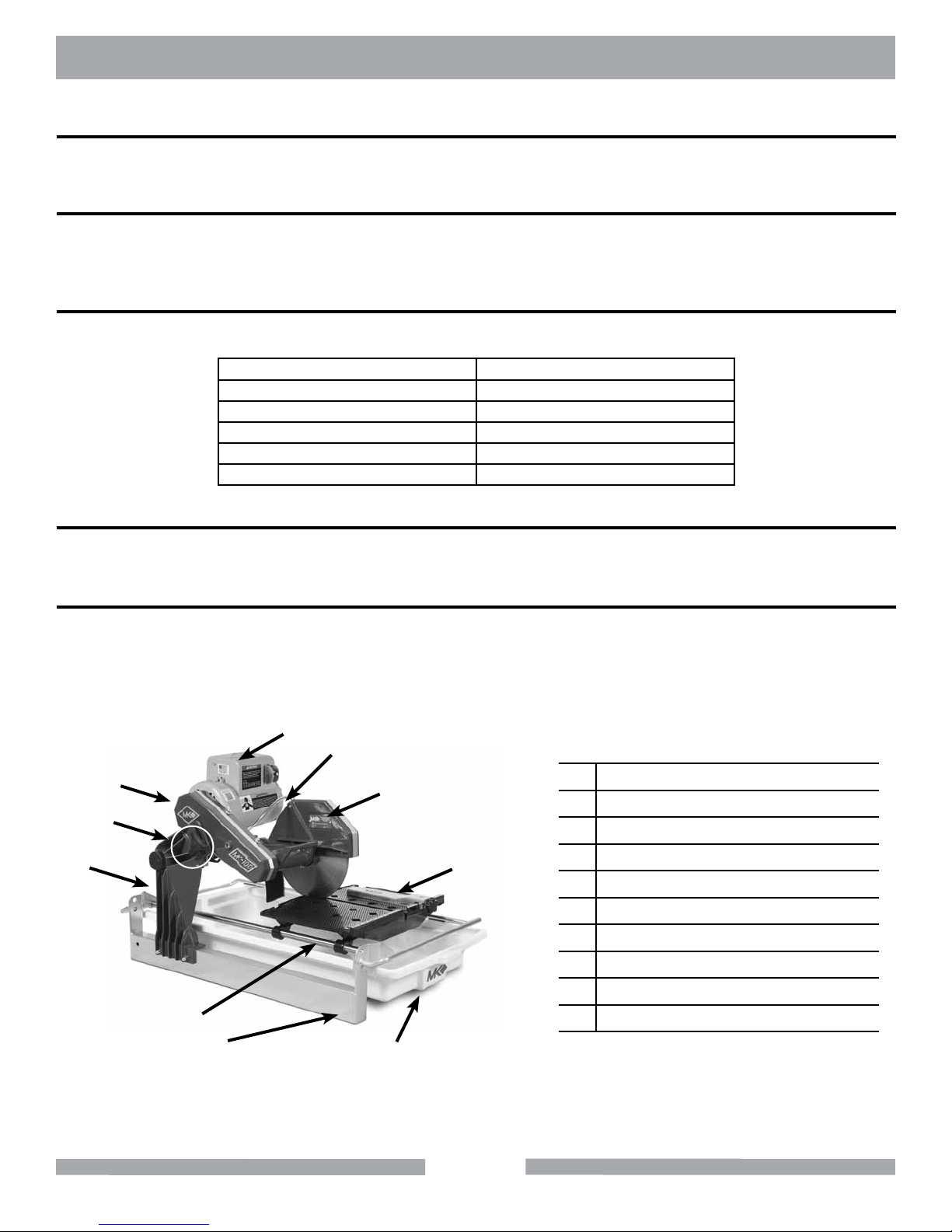
A
B
J
C
A Motor
B Water Pump Tube
H
I
D
C Blade Guard
D Cutting Table
E Water Basin
F Frame
G Guide Bar
H Post
G
F
I Depth of Cut Adjustment Knob
J Belt Guard
E
14
Page 15
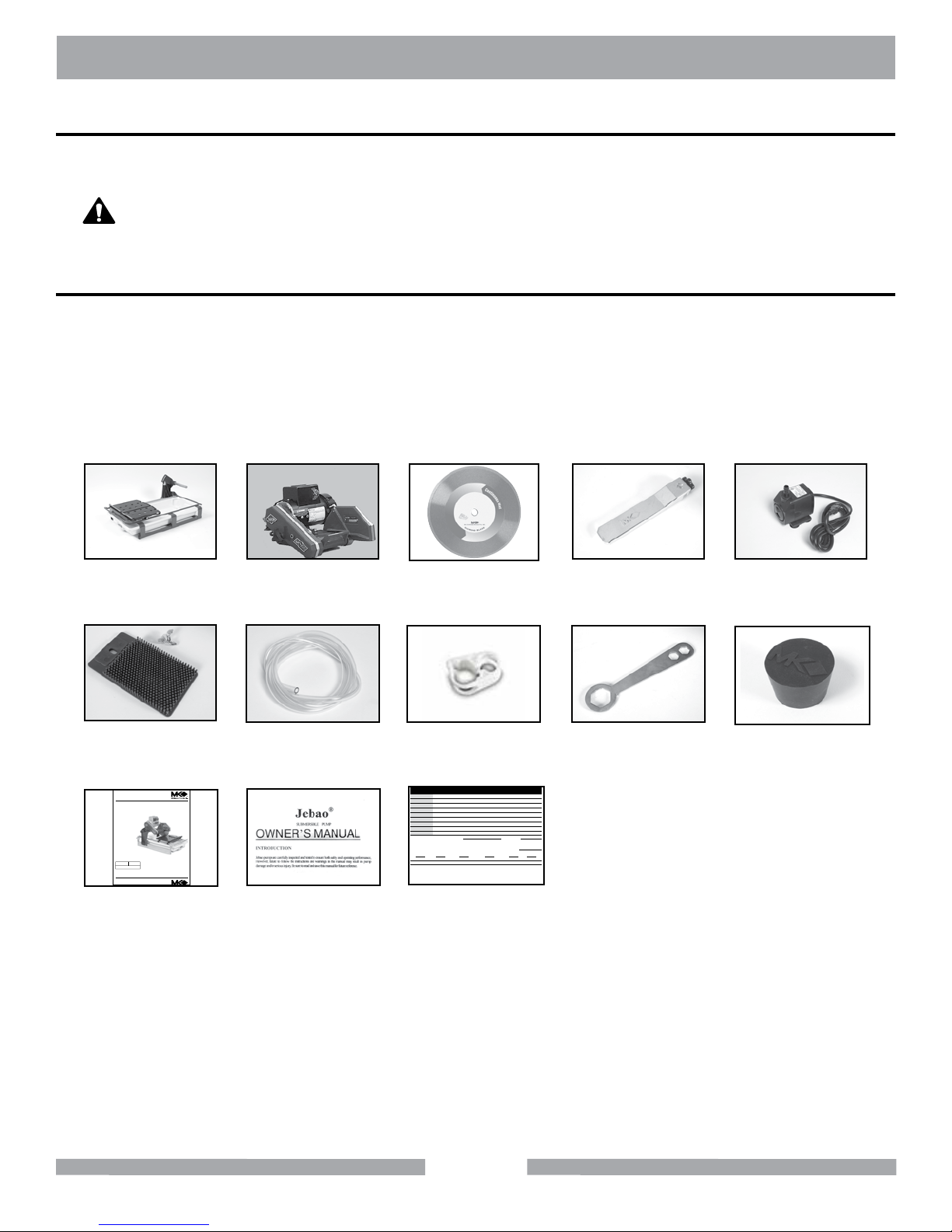
MK-100 TILE SAW CONTENT
UNPACKING
Your MK-100 has been shipped from the factory thoroughly inspected. Only minimal assembly is
required.
CAUTION
Use proper lifting techniques when lifting the MK-100.
If not done, remove the MK-100, Cutting Head and accessory box from the carton.
CONTENTS
In your container, you will find one (1) MK-100 frame and water basin, one (1) MK-100 cutting head,
one (1) 10-inch wet cutting continuous rim diamond blade, one (1) adjustable cutting guide, one
(1) electric water pump, one (1) splash guard, one (1) cooling transfer tube, one (1) flow adjusting
clamp, one (1) blade wrench, one (1) drain plug, one (1) owner's manual, one (1) pump manual and
one (1) warranty card.
MK-100 Frame
and Water Basin
MK-100
Cutting Head
Diamond Blade
Adjustable
Cutting Guide
Electric Water
Pump
Splash Guard
www.mkdiamond.com
Revision 104
Caution: Read all safety and operating instructions
before using this equipment. This parts list MUST
accompany the equipment at all times.
Manual Part# 158192
10.2014
MK-100 TILE SAW
OWNER'S MANUAL
PARTS LIST &
OPERATING INSTRUCTIONS
Owner's
Manual
Cooling
Transfer Tube
Pump
Manual
Flow
Adjusting Clamp
MK DiaMonD Warranty CarD
Name
address
City
state zip Code
phoNe Fax
e-mail
produCt model
part NumBer
maChiNe serial#
where did you purChase this saw From ? N a me
q tile distriButor q home CeNter q equipmeNt supply house
q tool supply q Bldg material supply q reNtal equipmeNt house
q or CoNtraCtor q IF so, what type? tile q masoNry q other
are you a do-it-yourselFer
what Criteria was importaNt iN ChoosiNg this saw? (rate From 1 to 5, 5 BeiNg the most importaNt)
power preCisioN porta Bility availaBility other
priCe
CommeNts or suggestioNs:
mK diamoNd warraNty
1315 Storm Parkway, Torrance, CA 90509 USA | www.mkdiamond.com | 1.800.421.5830 | 1.310.539.5158
If within one (1) Year from the date of purchase, this MK Diamond saw fails due to defect in material or workmanship, MK will repair it, free of charge when the unit is returned to the dealer where it was purchased. This warranty DOES NOT cover normal wear or damage resulting from operator abuse. In no event shall MK Diamond Products,
Inc. be liable for consequential damages arising out of the failure of any product if operated improperly. MK Diamond Products may act as a warranty station for motor/engine repairs based on an individual agreement with the manufacturer. This warranty is in lieu of all other warranties express or implied.
©2010 All Rights reserved. MK Diamond Products, Inc. • P/N 155037 MK Warranty Card (02/10)
date purChased
Warranty
Card
15
Blade Nut
Wrench
Drain Plug
Page 16
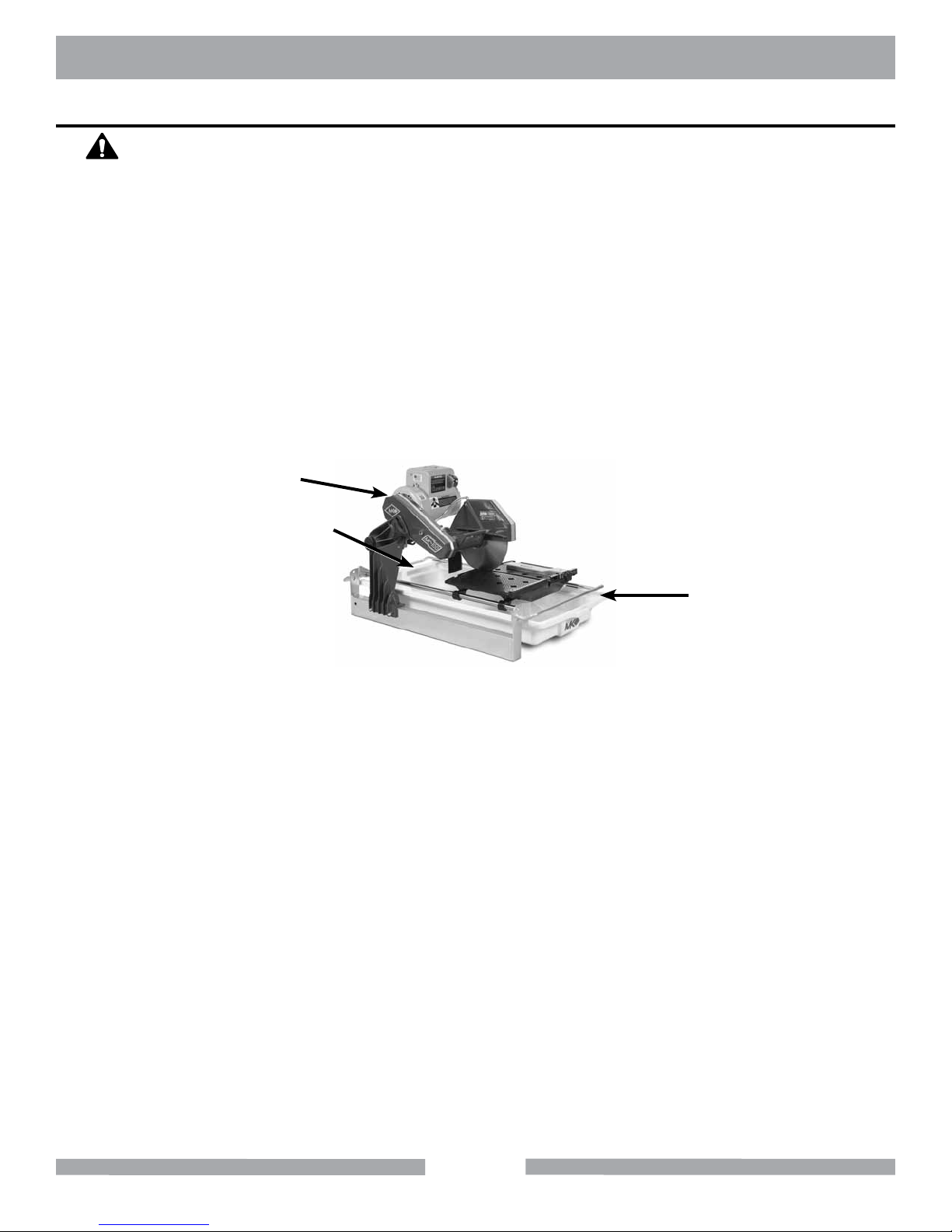
MK-100 TILE SAW TRANSPORT
TRANSPORT
CAUTION
1. The MK-100 weighs approximately ninety-six (96) pounds; use care when transporting.
2. Never transport the MK-100 with water in the Water Pan.
The MK-100 is designed with a rigid frame and removable Cutting Head. Two people are
required to transport the MK-100 with the Cutting Head installed. The Cutting Head must be
removed first, if one person is transporting the saw (see Cutting Head Installation and Removal
in the following section).
To lift the saw using two people, each person will grasp the front and back of the frame. To lift the
saw using one person, remove the Cutting Head first, and then grasp the front and back of the
frame. Transport the Cutting Head and the Frame separately.
Cutting
Head
Lift Point
Lift Point
16
Page 17
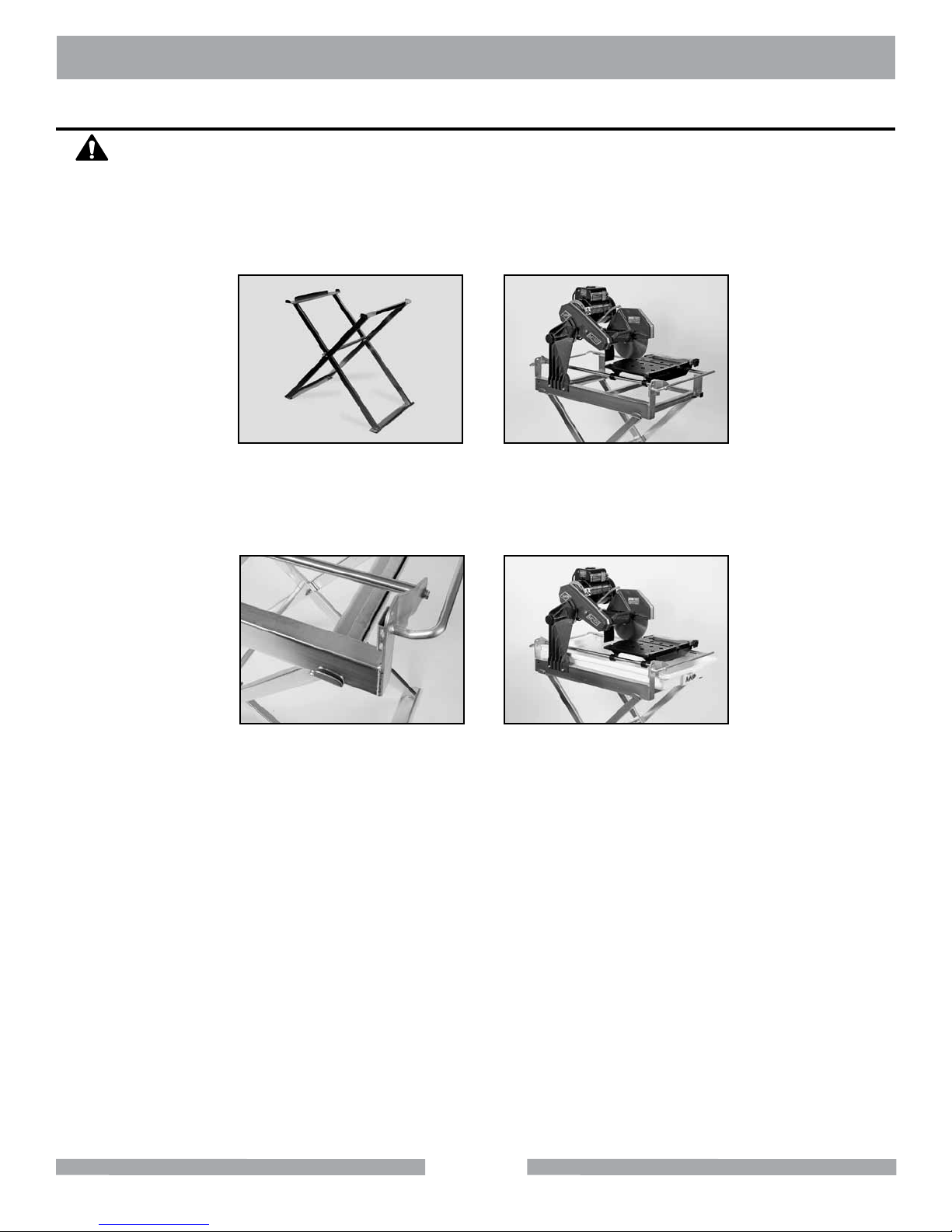
MK-100 TILE SAW STAND
FOLDING STAND
CAUTION
The MK-100 weighs ninety-six (96) pounds; follow the guidelines in the TRANSPORT
section when placing it on the stand (MK Diamond Part# 168244).
NOTE:
If using the Optional MK Diamond Stand, follow these steps.
(A)
Open the stand and place on at
surface. Remove Water Basin
from saw.
Place saw on stand.
(B)
(C)
Ensure saw frame is
positioned properly.
(D)
Reinstall the Water Basin.
17
Page 18
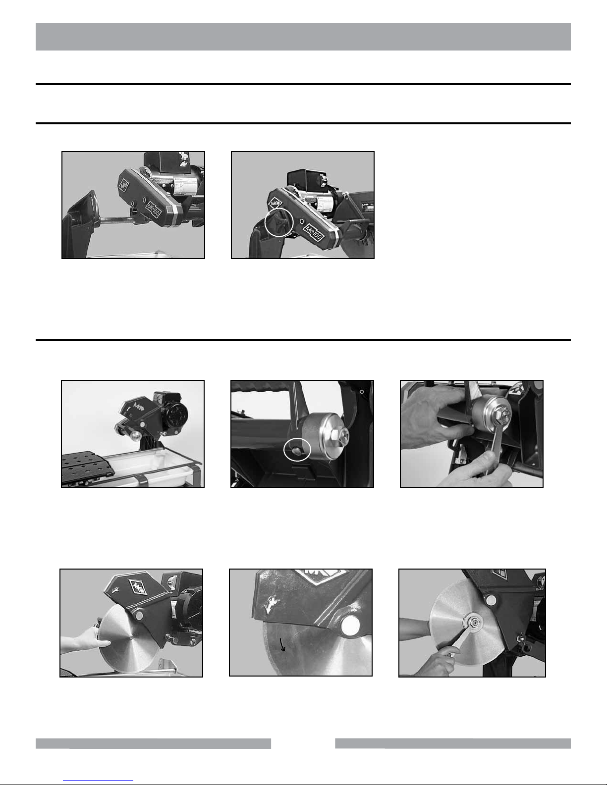
MK-100 TILE SAW ASSEMBLY
ASSEMBLY
Follow the assembly instructions to prepare your MK-100 for operation.
CUTTING HEAD INSTALLATION
NOTE:
If the Cutting Head is installed, go to the next step.
(A)
Align Cutting Head Rear
Pivot Hole to the Post Pivot
Shaft and slide onto shaft.
DIAMOND BLADE INSTALLATION
NOTE:
When installing the Retaining Nut, do not "cross-thread" and DO NOT over
tighten the nut.
(B)
Secure the Cutting Head by
installing the Adjusting Knob.
(A)
Position Movable Cutting
Table to the front of the saw
and raise the Blade Guard.
(D)
Install Diamond Blade onto
Blade Shaft. Verify the Blade is
seated on the Blade Shaft.
(B)
Locate the Shaft Lock but-
ton on the underside of the
Cutting Head.
(E)
Check the directional arrow on
the blade and direction of
rotation is correct.
18
(C)
Depress and hold the Shaft Lock
button and remove Retaining Nut
and Outer Flange using the
Blade Wrench.
(F)
Install Outer Flange and Retaining
Nut, depress and hold the Shaft
Lock button and tighten nut.
Page 19
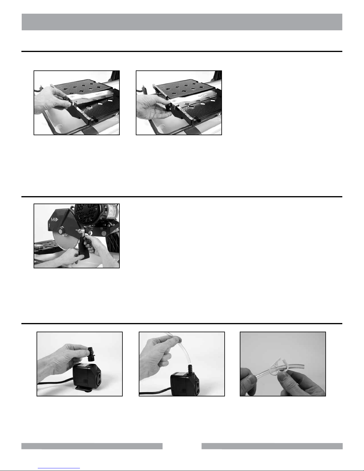
MK-100 TILE SAW ASSEMBLY
ADJUSTABLE CUTTING GUIDE INSTALLATION
NOTE:
Loosen Adjustable Cutting
Guide retaining thumbscrew
and place it over the Movable
Cutting Table Ruler/Stop.
The Adjustable Cutting Guide can be used on either side of the Diamond Blade.
(A)
SPLASH GUARD INSTALLATION
(B)
Place the Adjustable Cutting
Guide onto the Movable Cutting
Table Ruler/Stop and tighten the
retaining thumbscrew.
(A)
Install the retaining thumbscrew
through the washer and Splash Guard
then align to the hole found on back
of the Blade Guard and tighten.
WATER PUMP PREPARATION
(A)
Install Water Pump
Discharge Fitting.
(B)
Press one end of the Cooling
Transfer Tube into the Water
Pump Discharge Fitting.
19
(C)
Slide Cooling Flow Adjust-
ing clamp on to the Cooling
Transfer Tube.
Page 20
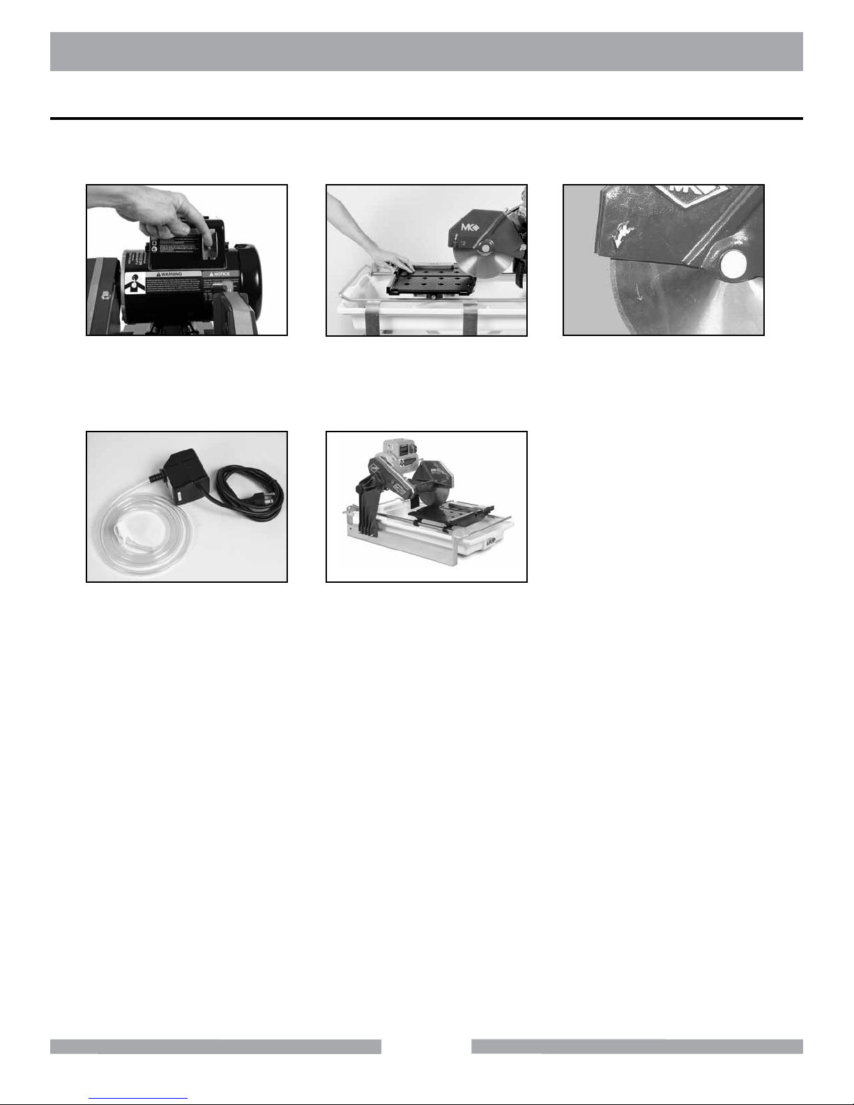
MK-100 TILE SAW SETUP
PRE-START INSPECTION
Prior to beginning work, a pre-start inspection of the saw should be performed.
(A)
Ensure the ON/OFF Switch
is in the OFF position.
(D)
Inspect the Pump Assembly
for damage. Ensure the cord
is free of cracks or cuts.
(B)
Verify the Movable Cutting
Table moves freely.
(E)
Inspect the MK-100 for
damage. Ensure the cord is
free of cracks or cuts.
(C)
Inspect the Diamond Blade for
damage. Verify the blade is cor-
rect for the material being cut.
20
Page 21
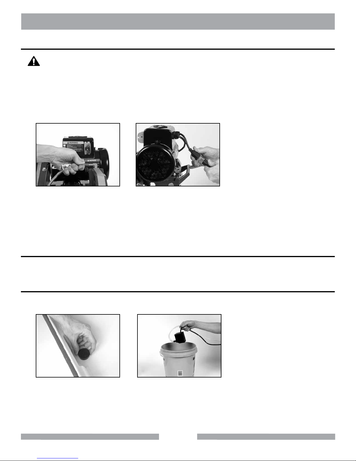
MK-100 TILE SAW SETUP
CONNECTING WATER PUMP
WARNING
To prevent the possibility of electrical shock, the MK-100 MUST be de-energized
when connecting the Water Pump.
To prevent the possibility of electrical shock, use only MK Diamond qualified
replacement parts.
NOTE:
To prevent pump damage, the Water Pump must be disconnected from its power
supply if cutting with a Dry Blade.
(A)
Connect the Cooling
Transfer Tube to the
inlet connection of the
Blade Guard.
(B)
Connect the Water Pump
power cord to the connection
found on the back of the motor.
WATER PUMP SETUP FOR OPERATION
The Water Pump can be setup for operation in two ways, external water source or Re-circulation.
EXTERNAL WATER SOURCE
This is the preferred method of cooling.
(A)
Remove the Drain Plug.
Place empty container under
hole for water drainage.
Place the Water Pump in an
external container and ll until
water completely covers the
Water Pump suction.
(B)
21
Page 22
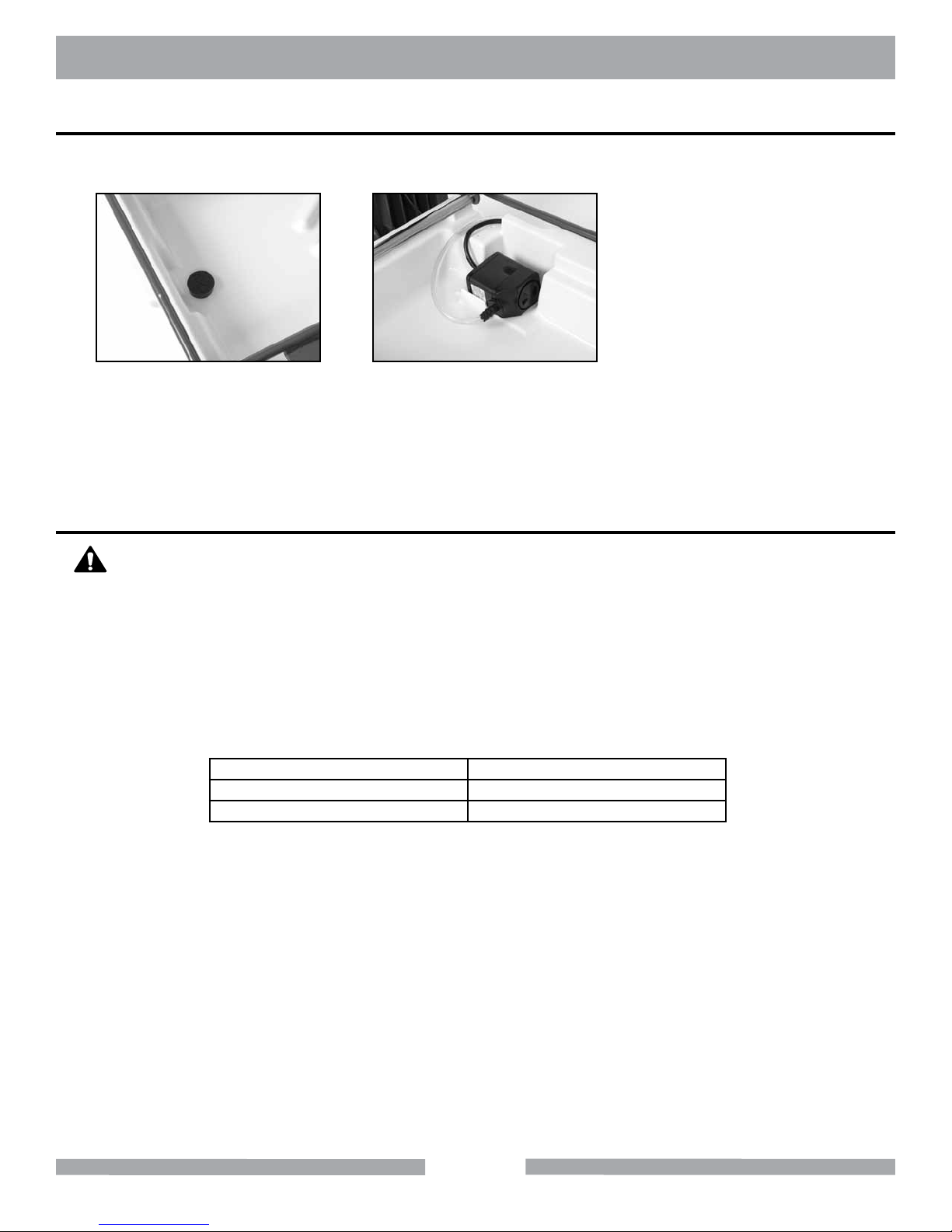
MK-100 SETUP
RE-CIRCULATION
NOTE:
NOTE:
When using the re-circulation method, the water should be changed often for longer pump life.
(A)
Ensure the Drain Plug is in-
stalled in the Water Basin.
Ensure the power cord and cooling tube exit the water basin under the top rail of the frame.
MK-100 SETUP FOR OPERATION
CAUTION
Before powering or starting, check for damage that could prevent this equipment
from proper operation or performing it's intended function. Check for binding and
alignment of moving parts. Check for damaged, broken, or missing parts.
(B)
Place the Water Pump in the
back of the Water Basin.
Verify the ON/OFF switch is in the OFF position.
Before connecting the MK-100 to a power supply, be sure the voltage, cycle and phase of the job
site power source meet the requirements in the table below.
Voltage 120v
Cycle 60Hz
Phase 1-phase
If using an extension power cord, make sure the length and wire gauge correspond to he
requirements listed in the Table on Page 10. An extension power cord that is too small in wire gauge
(diameter), or too long in length, will cause the motor to overheat and could cause premature failure.
Use an approved Ground Fault Circuit Interrupter (GFCI).
Do not cover the motor vents as this could lead to motor overheating.
NOTE:
In order to avoid breaker tripping, a 20 amp circuit breaker should be used.
22
Page 23
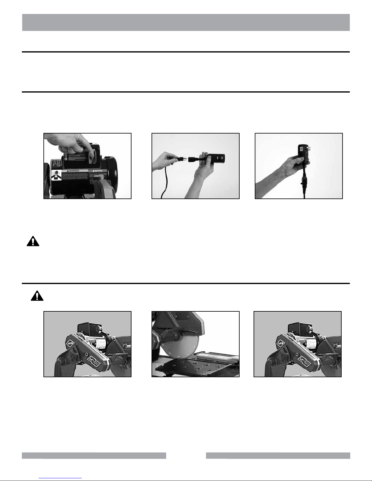
MK-100 OPERATION
PORTABLE GENERATOR
If using a portable generator to provide power, ensure the generator meets the following minimum
requirements: 8Kw 120 Volts 20 Amps Single Phase
GROUND FAULT INTERRUPTER
Ground Fault Interrupters (GFCI) provide protection from the dangers of electrical hazards.
Receptacles are available having built-in GFCI protection and may be used for this measure of safety.
Otherwise a GFCI should be used.
(A)
Ensure the ON/OFF Switch is
in the OFF position.
WARNING
If the plug or receptacle does get wet DO NOT plug/unplug the cord.
Disconnect the fuse or circuit breaker that supplies power to the tool.
Then unplug and examine for presence of water in the receptacle.
SET CUTTING DEPTH
CAUTION
When loosening the Cutting Head Adjusting Knob, the Cutting Head will pivot
down unless held.
(B)
Plug MK-100 into GFCI.
(C)
Plug the GFCI into
the power source.
(A)
Loosen Cutting Head
Knob and move Cutting
Head down.
(B)
Set cutting depth approxi-
mately 1/4 to 1/2 inch below
the surface of the Movable
Cutting Table.
23
(C)
Ensure the Adjusting
Knob is tight.
Page 24
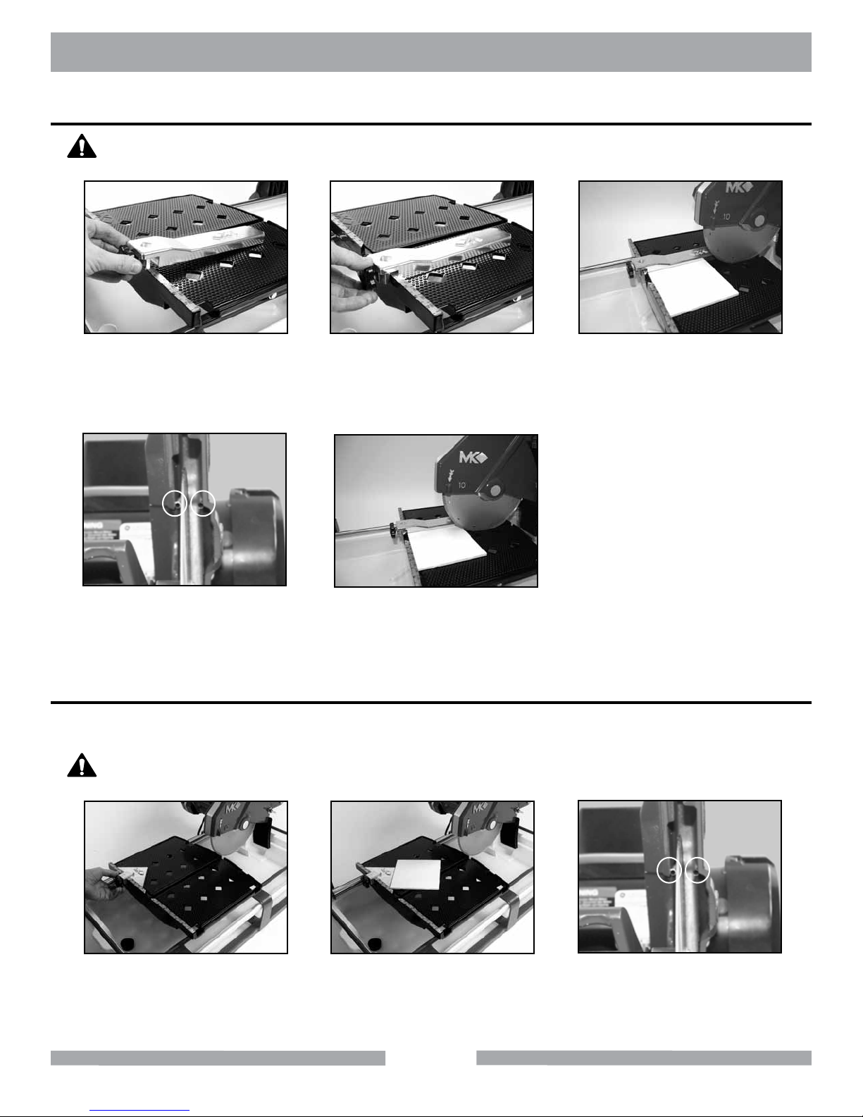
MK-100 OPERATION
Cutting Straight Edges
CAUTION
DO NOT FORCE THE TOOL. It will do the job better and safer at the rate for
which it was designed.
(A)
Loosen the Adjustable Cutting
Guide retaining thumbscrew.
(B)
Position the Adjustable Cutting
Guide to desired cut length indicated inside the diamond and tighten.
(C)
Place the tile against the Ruler/
Stop and Cutting Guide.
Turn the motor ON.
(D)
Verify proper cooling ow on both
sides of the blade (See Maintenance
Section to increase/decrease ow).
Diagonal Cut
NOTE:
To cut diagonals, the Dual 45° Flat Angle Guide (MK Diamond Part No. 134557-MK)
should be used.
CAUTION
DO NOT FORCE THE TOOL. It will do the job better and safer at the rate for
which it was designed.
(A)
Position the Dual 45° Flat
Angle Guide and tighten the
retaining thumbscrew.
(E)
Perform the cut. Turn the motor
OFF when work is complete.
(B)
Position the tile against the Dual
45° Flat Angle Guide and the
Ruler/Stop. Turn ON the motor.
(C)
Verify proper cooling ow on both
sides of the blade (See Maintenance
Section to increase/decrease ow).
24
Page 25
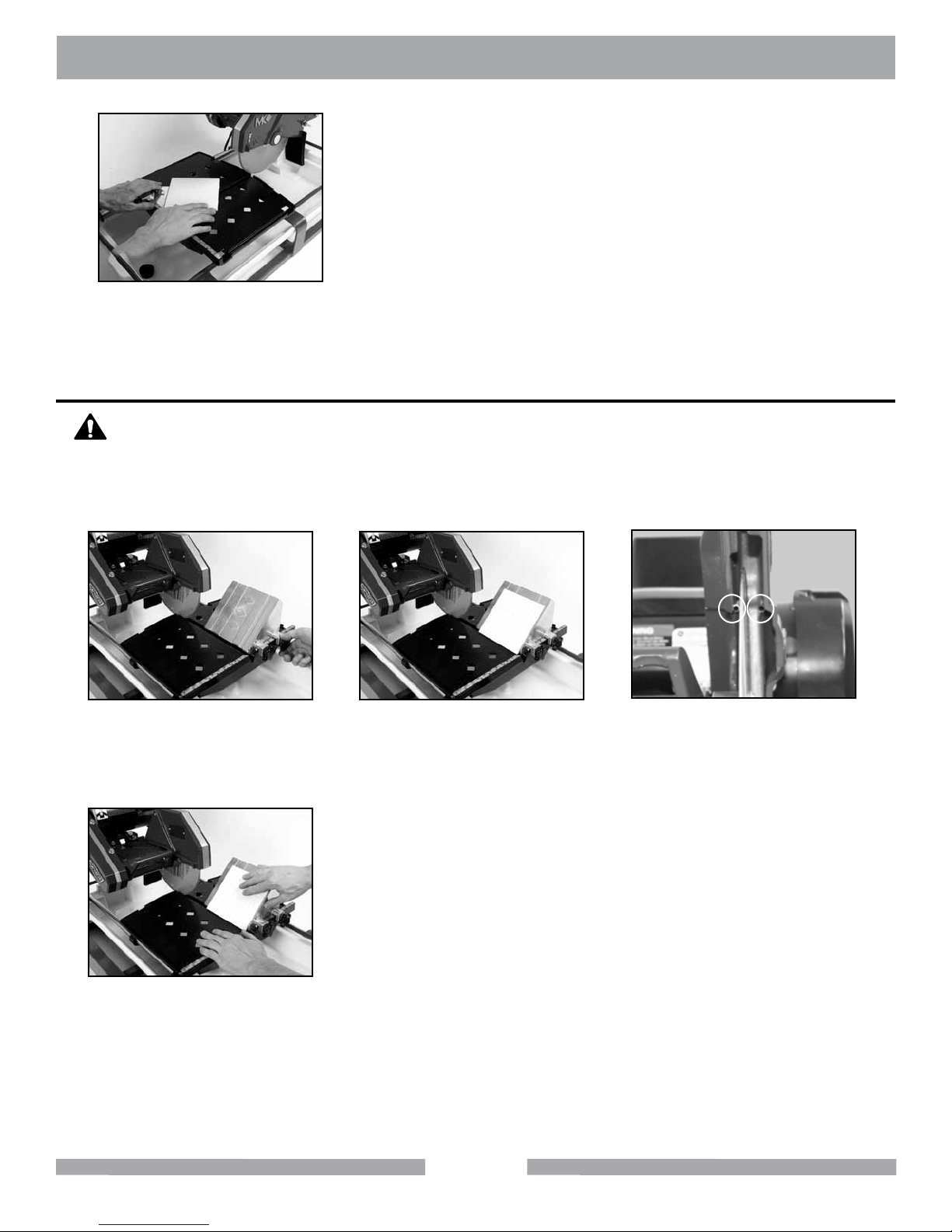
MK-100 OPERATION
(D)
Perform the cut. Turn the motor
OFF when work is complete.
45° Miter Cutting
CAUTION
DO NOT FORCE THE TOOL. It will do the job better and safer at the rate for
which it was designed.
NOTE:
To cut 45° Miters, the 45° Bullnose Miter Guide should be used (MK Diamond
Part # 134585-MK).
(A)
Position the 45° Bullnose
Miter Guide and tighten the
retaining thumbscrews.
(B)
Position the tile on the 45°
Bullnose Miter Guide and the
Ruler/Stop. Turn ON the motor.
(C)
Verify proper cooling ow on
both sides of the blade (See
Maintenance Section to
increase/decrease ow).
(D)
Perform the cut. Turn the motor
OFF when work is complete.
25
Page 26
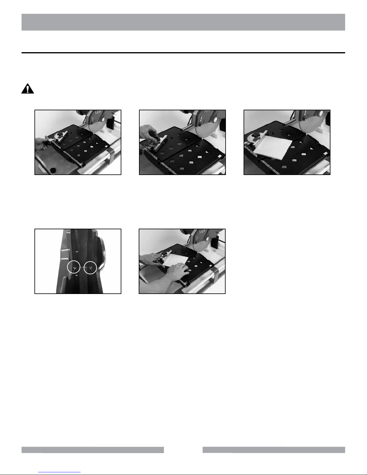
MK-100 OPERATION
Off-angle Cutting
NOTE:
To cut angles other than 45° angles or Miter, a 90° Protractor (MK Diamond Part
No. 134569-MK) should be used.
CAUTION
DO NOT FORCE THE TOOL. It will do the job better and safer at the rate for
which it was designed.
(A)
Place the 90° Protractor on
the Ruler/Stop and tighten the
retaining thumbscrew.
(B)
Set the desired angle and
tighten the thumbscrew.
(C)
Position the tile against the 90°
Protractor and the Ruler/Stop.
Turn the motor ON.
(D)
Verify proper cooling ow on both
sides of the blade (See Mainte-
nance Section to increase/de-
crease ow).
(E)
Perform the cut. Turn the motor
OFF when work is complete.
26
Page 27
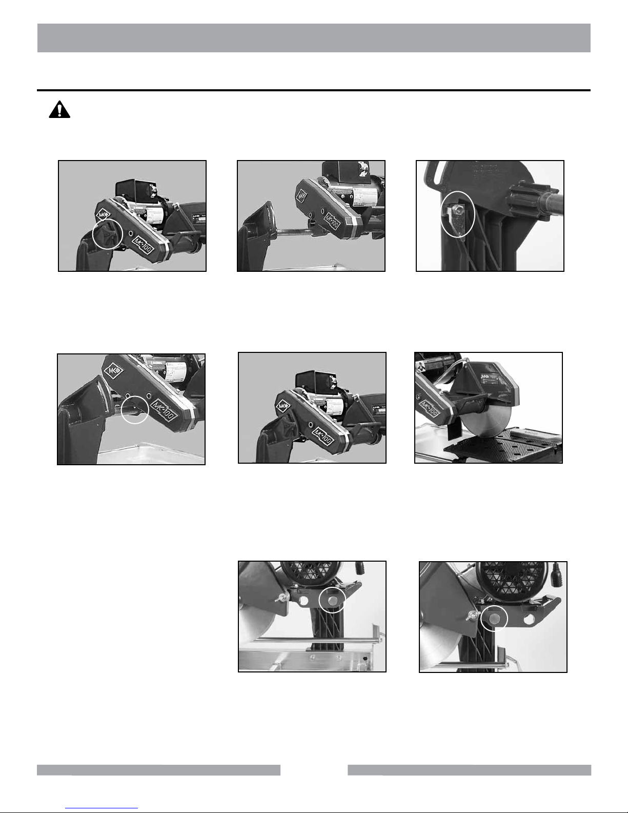
MK-100 CUTTING HEAD ADJUSTMENT
Adjusting the Cutting Head
CAUTION
The Cutting Head is heavy. When loosening the Cutting Head Adjustment Knob,
the Cutting Head will pivot down unless held. Care must be used when changing
the position of the Cutting Head.
(A)
Remove the blade. Support the
Cutting Head and then remove
Adjusting Knob.
(B)
Remove the Cutting Head from
the rear pivot hole.
(C)
Move Cutting Head Stop
to down position.
(D)
Install the Cutting Head onto
the front pivot hole.
NOTE: Move Cutting Head
Stop in upward
position when using
rear pivot hole and
in the down position
when using front
pivot hole.
(E)
Install the Adjusting Knob.
For small tiles (6" tile or smaller)
the Cutting Head should be
in the rear pivot hole and the
Motor Post should be in the
forward post retaining hole.
27
(F)
Install Diamond Blade. Set
cutting depth approx. 1/4 to 1/2
inch below the surface of the
Movable Cutting Table.
For maximum cutting length,
the Cutting Head should be
in the front pivot hole and the
Motor Post should be in the
rear post retaining hole.
Page 28
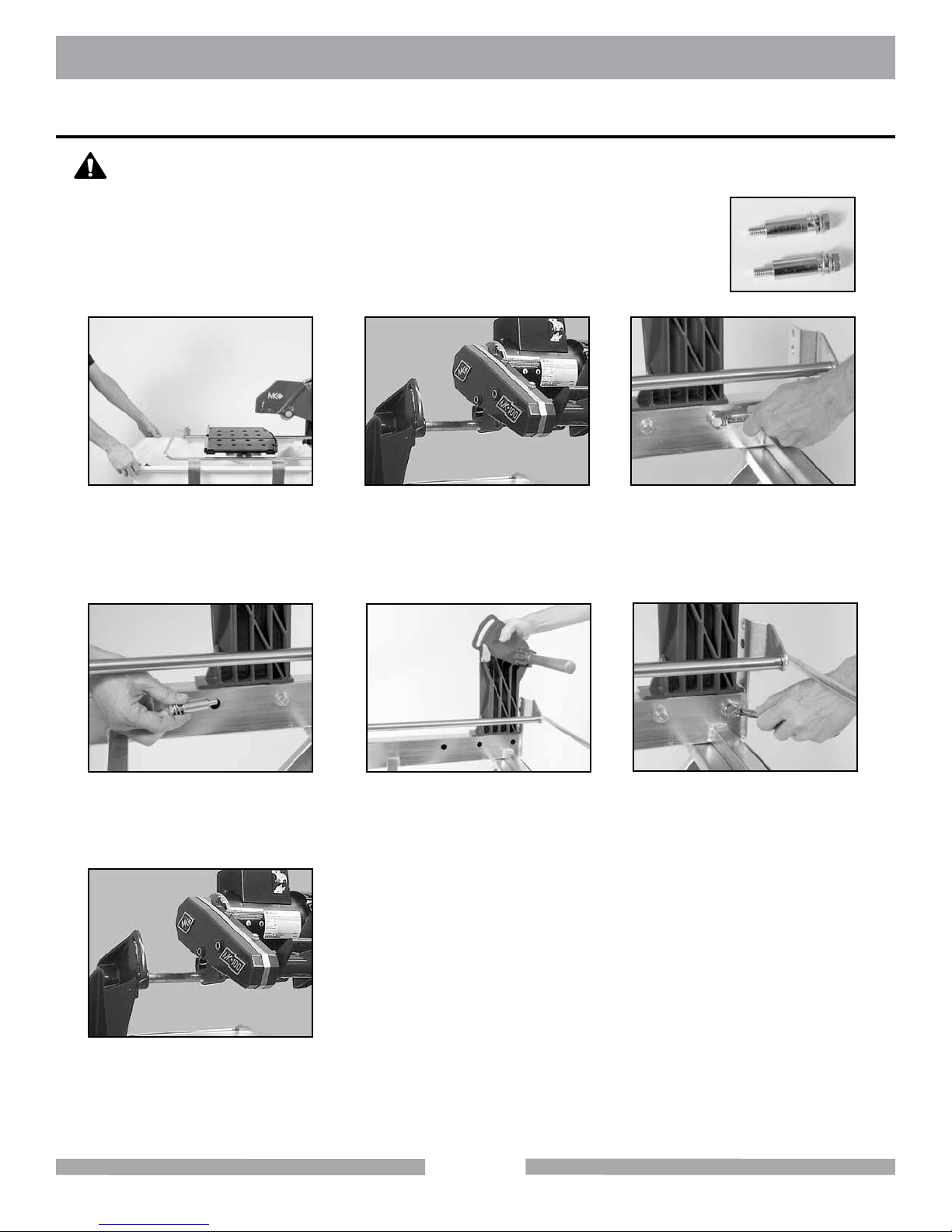
MK-100 CUTTING HEAD ADJUSTMENT
Adjusting the Motor Post for Maximum Cutting Length
CAUTION
The Cutting Head and Motor Post are heavy. Care must be used when changing
the position of the Cutting Head.
NOTE:
Do not unscrew the Motor Post Retaining Bolts completely. There
is a Stand Off that needs to be removed with the Retaining Bolts.
(A)
Remove Water Basin and Blade.
Secure the Cutting Head and
then remove Adjusting Knob.
(B)
Remove the Cutting Head
(Cutting Head Adjustment pg 25).
(C)
Loosen the Retaining Bolts.
(D)
Remove both the Standoffs
and Retaining Bolts.
(G)
Install the Cutting Head in
rear Pivot Hole (Cutting Head
Adjustment pg 25).
(E)
Relocate the Post to the rear
Post retaining holes.
28
(F)
Install the Post Support and
tighten Retaining Bolts.
Page 29
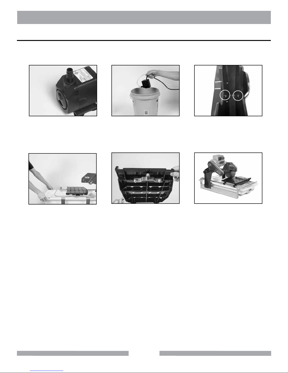
MK-100 CLEANUP
CLEANUP
NOTE:
If an external water source was used, steps A through C may be skipped.
Dispose of waste water in accordance with applicable Federal, State and Local laws.
(A)
Clean the Water Pump
suction of all debris
Place the Water Pump in an
external container
(B)
(C)
Run the MK-100 until clear
water is seen at the blade
cooling ports (Approx. 1 min.)
(D)
Remove the Water Basin
and clean.
(E)
Clean the Movable
Cutting Table Roller Wheel
and Frame Support
(F)
Clean the remainder of the
MK-100
29
Page 30
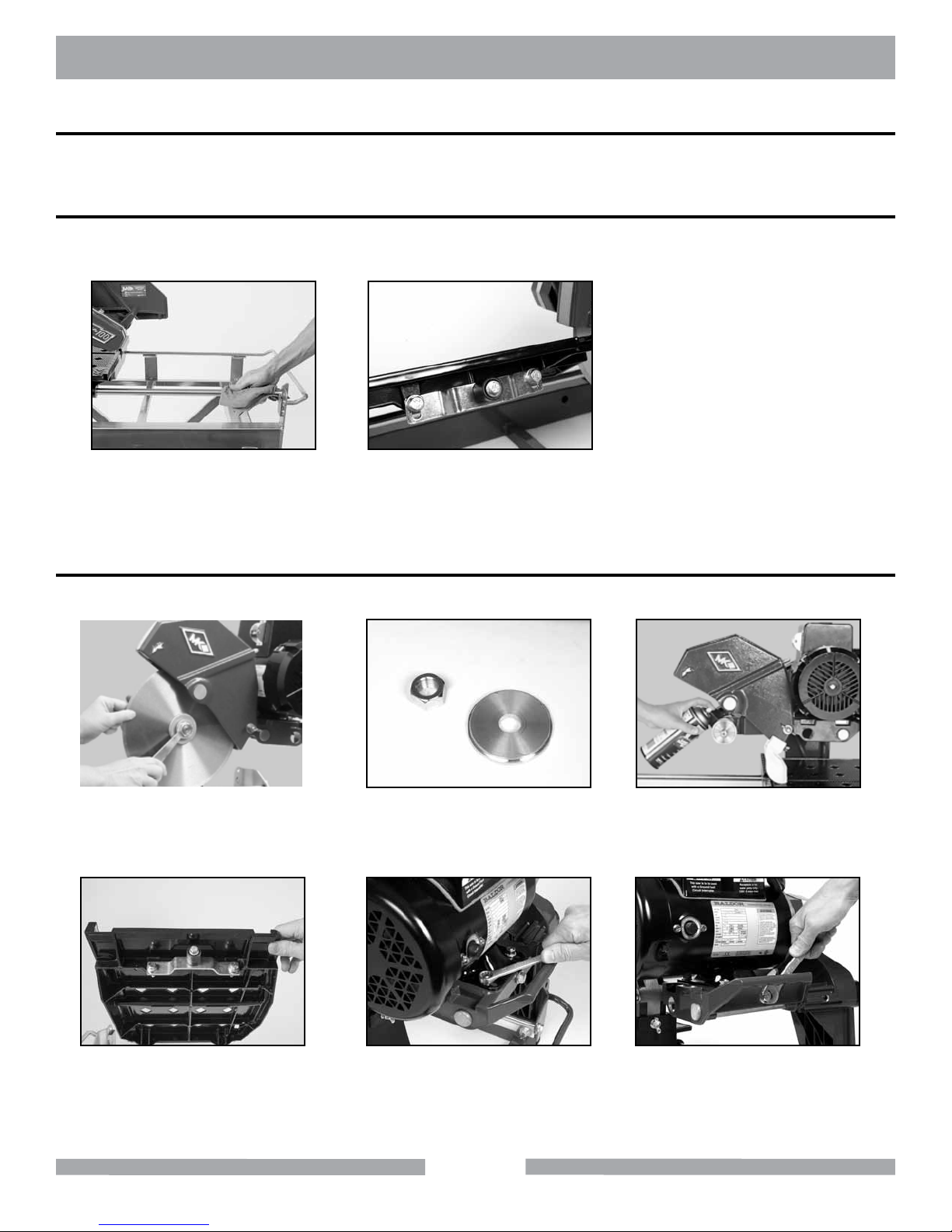
MK-100 MAINTENANCE
MAINTENANCE
Perform the following after initial purchase and operation of the MK-100.
Maintenance Following Use
To extend the life of the MK-100, the following procedure should be performed after each use.
Lubricate all points listed below with light oils such as, 3 in 1, WD-40, etc.
(A)
Lubricate the Guide Bar.
Lubricate the Roller
Wheel Assembly.
(B)
Monthly Maintenance
The following maintenance should be performed monthly.
(A)
Remove the Diamond Blade.
Clean and lubricate the Outer
Flange and Retaining-nut.
(B)
(C)
Lubricate the Arbor Shaft.
(D)
Verify the Roller Wheel
Assembly is tight and in
good condition.
(E)
Verify all motor mounting
Bolts are tight.
30
(F)
Verify the Motor Adjustment
Strap is tight.
Page 31
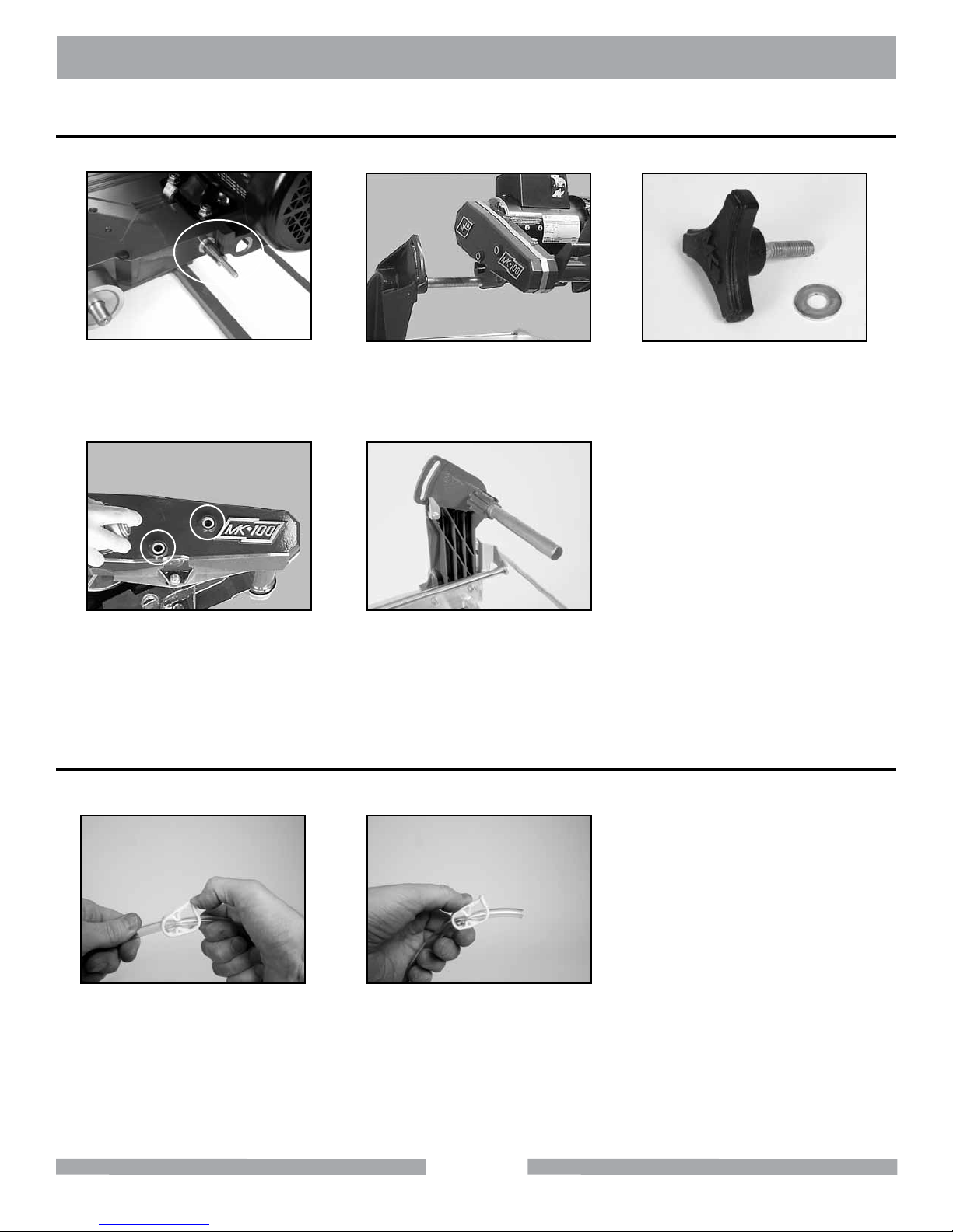
MK-100 MAINTENANCE
Monthly Maintenance Cont.
(G)
Remove the Blade Guard.
Lubricate the Blade Guard
Pivot Shaft.
(J)
Lubricate the Cutting Head
Adjustment Knob
retaining holes.
Flow Adjustment
NOTE:
If flow to the diamond blade requires adjustment, perform the following actions.
(H)
Remove the Cutting Head (Cut-
ting Head Adjustment pg 25).
(K)
Lubricate the Cutting Head
Pivot Shaft.
(I)
Lubricate the threads on the
Cutting Head Adjustment
Knob.
(A)
Increase cooling ow
by releasing the Flow
Adjusting Clamp.
(B)
Reduce cooling ow by
pressing down on the Flow
Adjusting Clamp.
31
Page 32
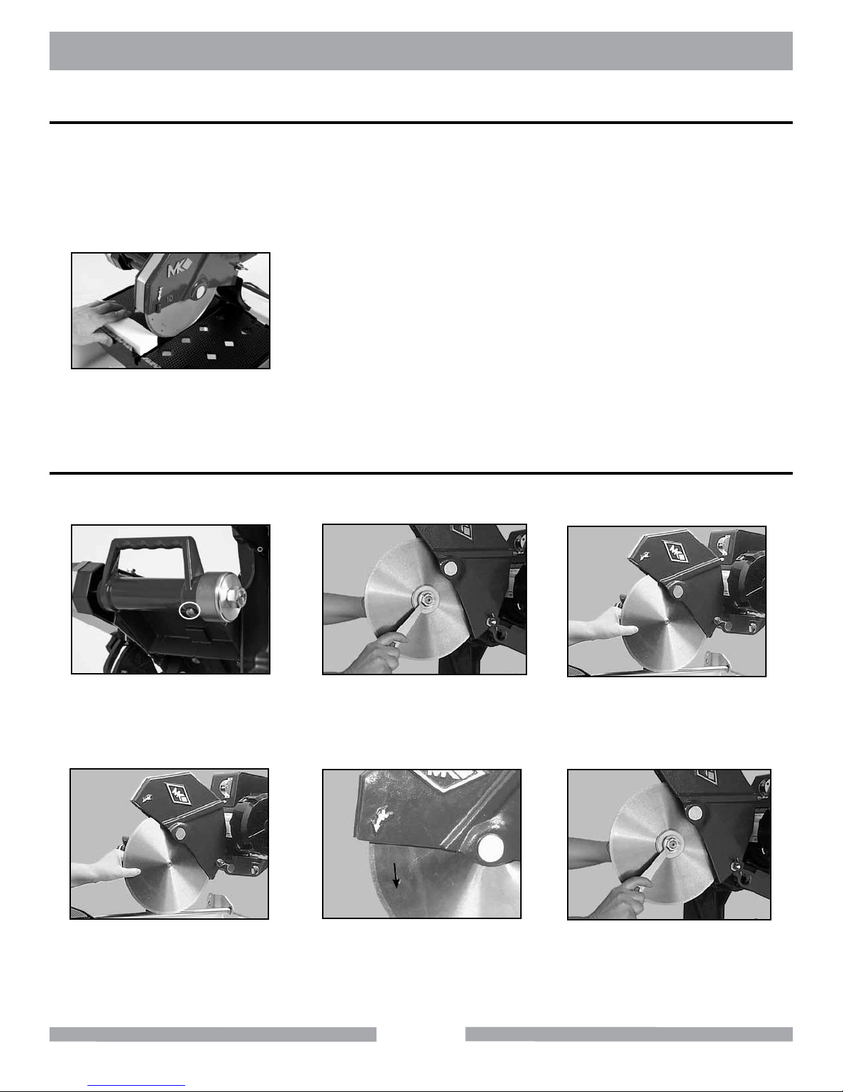
MK-100 MAINTENANCE
Blade Dressing
Like most cutting instruments, a diamond blade performs best when it is dressed. Over time and use,
diamonds on the outer edge of the blade may become smoothed or "glazed" over. This will reduce
grinding efficiency and may cause the blade to "wander" or bend giving the illusion of an alignment
problem. When this occurs, the blade will need to be dressed. The diamond blade can be dressed
using the MK Dressing Stick (MK Diamond part number 152972) and by following the steps below.
(A)
Cut the Dressing Stick 7 or 8
times to dress the Blade.
Diamond Blade Change-out
NOTE:
When installing the Retaining Nut, DO NOT "cross-thread" and DO NOT over tighten the
nut.
(A)
Locate the Shaft Lock, push
button on the underside of the
Cutting Head.
(B)
Remove Retaining Nut and Outer
Flange, depress and hold the Shaft
Lock hold button and loosen.
(C)
Remove the Diamond Blade.
(D)
Install the new Diamond
Blade onto Blade Shaft.
Install Outer Flange and
Retaining Nut.
(E)
Verify the Blade is seated on
the Blade Shaft and direction
of rotation is correct.
32
(F)
Depress and hold the Shaft Lock
button and tighten Retaining Nut.
Page 33
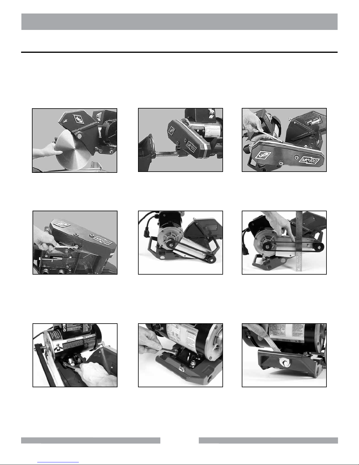
MK-100 MAINTENANCE
V-Belt Inspection, Adjustment and Replacement
The MK-100 is designed with power transmission Micro-V Belt. In order to ensure the MK-100
operates a peak efficiency, the Micro-V Belt should be inspected monthly, and changed if the Micro-V
Belt shows damage and/or excessive wear.
NOTE:
When a new belt is installed, it should be inspected and re-tensioned after the first
forty-eight (48) hours of operation.
(A)
Remove the Diamond Blade.
(B)
Remove the Cutting Head
(See Cutting Head Adjust-
ment Pg. 25).
(C)
Remove the two top
Belt Guard Bolts.
(D)
Remove Belt Guard
bottom bolt.
(G)
Loosen the two front motor
mounting bolts. If re-tension-
ing only, go to step N.
(E)
Inspect the Micro-V Belt for
cracks, fraying, separation and
wear. Go to step H if
replacement is required.
(H)
Loosen the two back motor
mounting bolts.
33
(F)
Check belt for proper tension.
If tension correct, go to step Q
(proper tension should be
1/8-inch deection).
(I)
Loosen the Motor Adjustment Strap.
Page 34
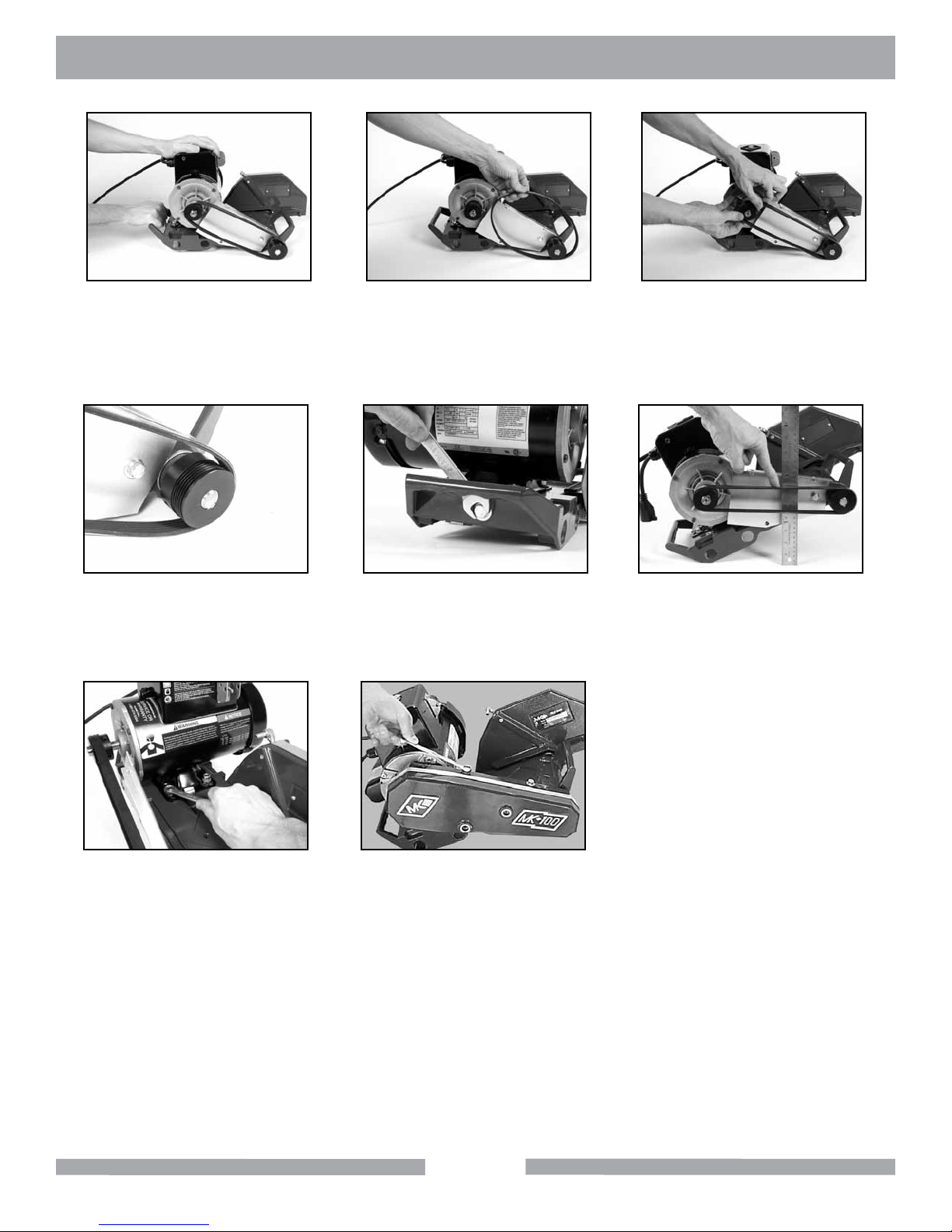
MK-100 MAINTENANCE
(J)
Push the motor toward the
front of the Cutting Head to
loosen the V-Belt.
(M)
Verify the V-Belt is seated in
the grooves of both pulleys.
(K)
Remove the V-Belt.
(N)
Tighten the Motor Adjustment
Strap to remove slack.
(L)
Install the new V-Belt
(MK Diamond Part No. 158194).
(O)
Check V-Belt tension (proper
tension 1/8-inch) Repeat steps N
and O until proper Micro-V Belt
tension is achieved.
(P)
Tighten the four motor
mounting bolts.
(Q)
Install the Belt Guard.
34
Page 35
MK-100 MAINTENANCE
Cooling Flow
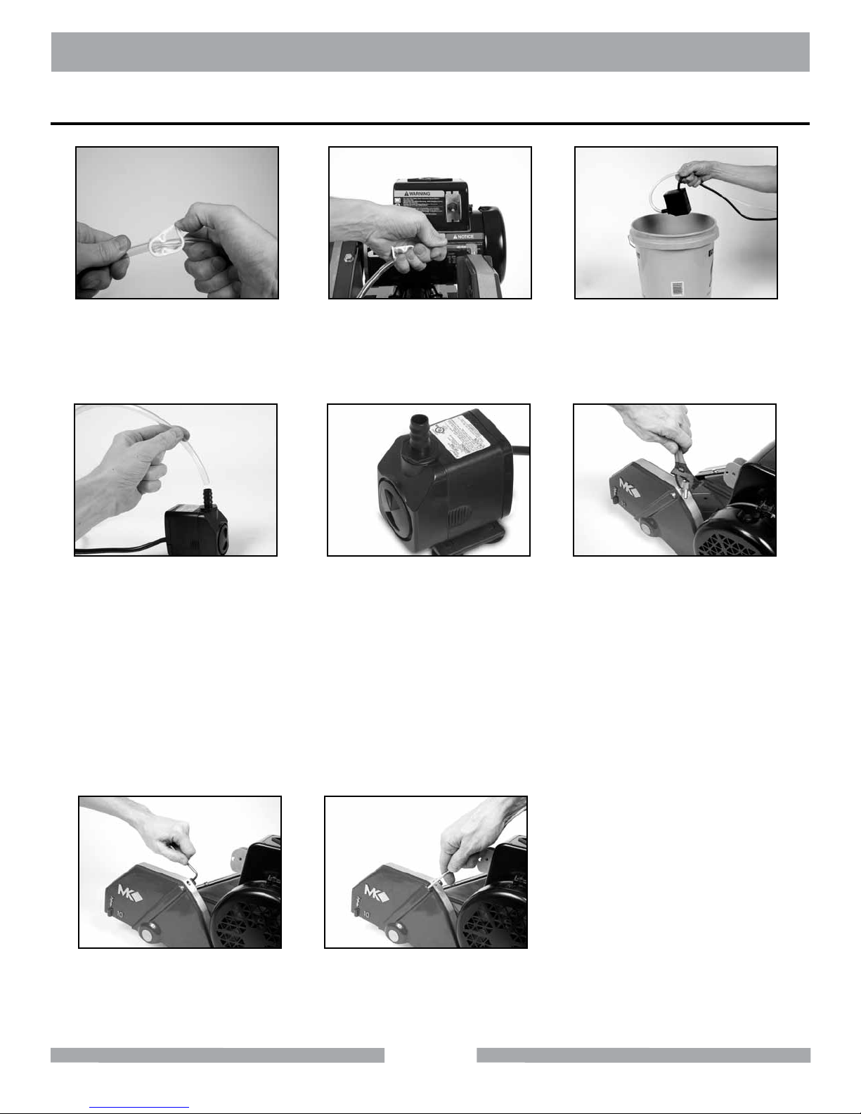
(A)
Check cooling ow Adjusting
Clamp open.
(D)
Remove the Cooling Transfer
Tube and check ow.
NOTE:
"Rodding" cooling channels is performed by inserting a small wire rod through the
cooling inlet on top of the Blade Guard and directing the rod out through each of the
cooling flow tubes located on the underside of the Blade Guard. The cooling channels
should be "rodded" until all ports are free of foreign debris.
(B)
Remove the Cooling
Transfer Tube from the
Blade Guard inlet.
(E)
Inspect and clean pump.
See Pump Manual.
(C)
Place Pump into a bucket of
water and check ow.
(F)
Remove the Blade Guard
Intake Fitting and check.
(G)
Remove the Cooling
Channel cover screws.
(H)
Rod Cooling Channels
and recheck ow.
35
Page 36
MK-100 TROUBLESHOOTING
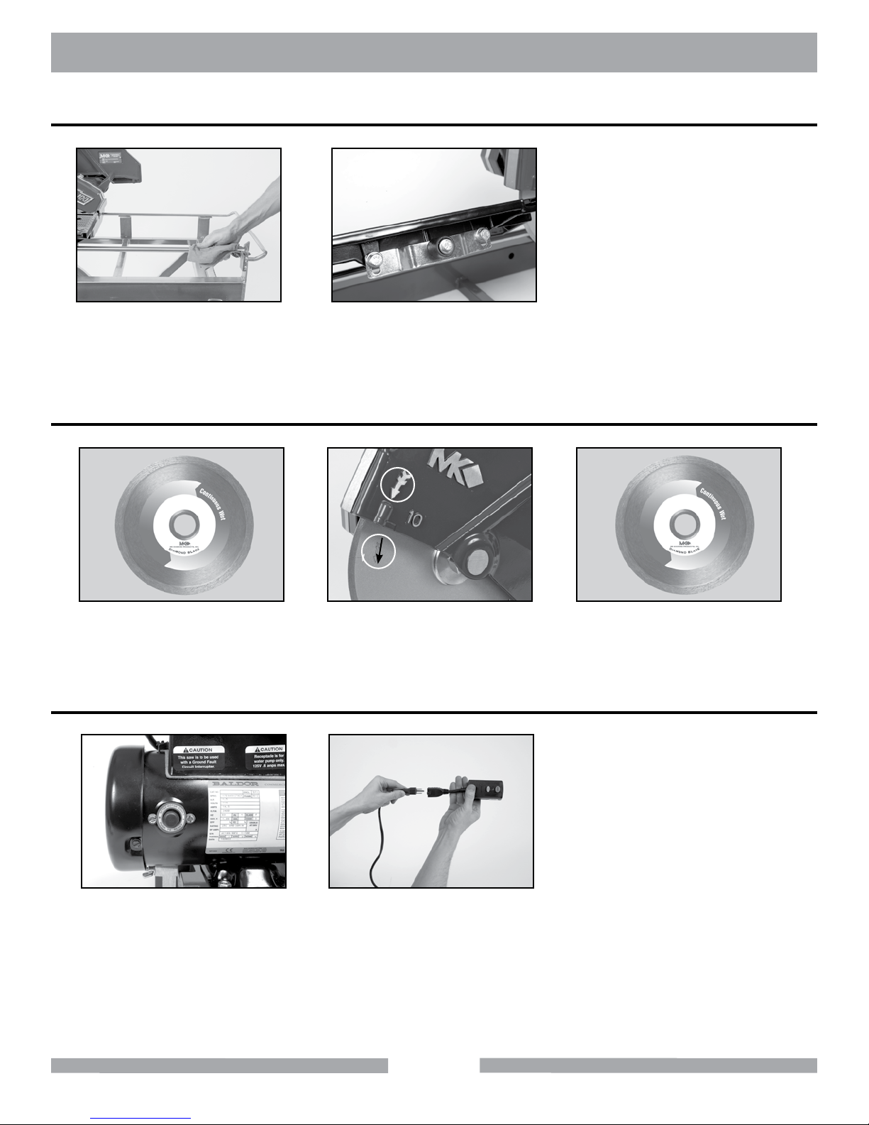
Movable Cutting Table Does Not Move Correctly
(A)
Check that the Guide Bar is
clean - clean if dirty.
Blade will not cut properly
(A)
Check for smoothness
or "Glazing" (See Blade
Dressing Section)
Blade Stops Turning
(B)
Check the Movable Cutting
table Roller Wheels for wear,
replace if necessary.
(B)
Check for proper blade rota-
tion. Ensure arrow engraved on
blade matches the directional
arrow on Blade Guard.
(C)
Ensure the Blade Core is not
bent. Verify the blade is correct
for the material being used.
(A)
Allow motor to cool and
depress motor Overload
Reset Switch.
NOTE:
Verify circuit breaker at least 20 amps - if not, move to 20-amp circuit.
Verify circuit breaker not tripped. If tripped, reset once.
Check power source voltage is 120V - if not 120V, move to another circuit.
(B)
Verify all plugs fully
installed. Check Ground
Fault Circuit Interrupter.
36
Page 37

NOTES
37
Page 38
MK-100 EXPLODED VIEW
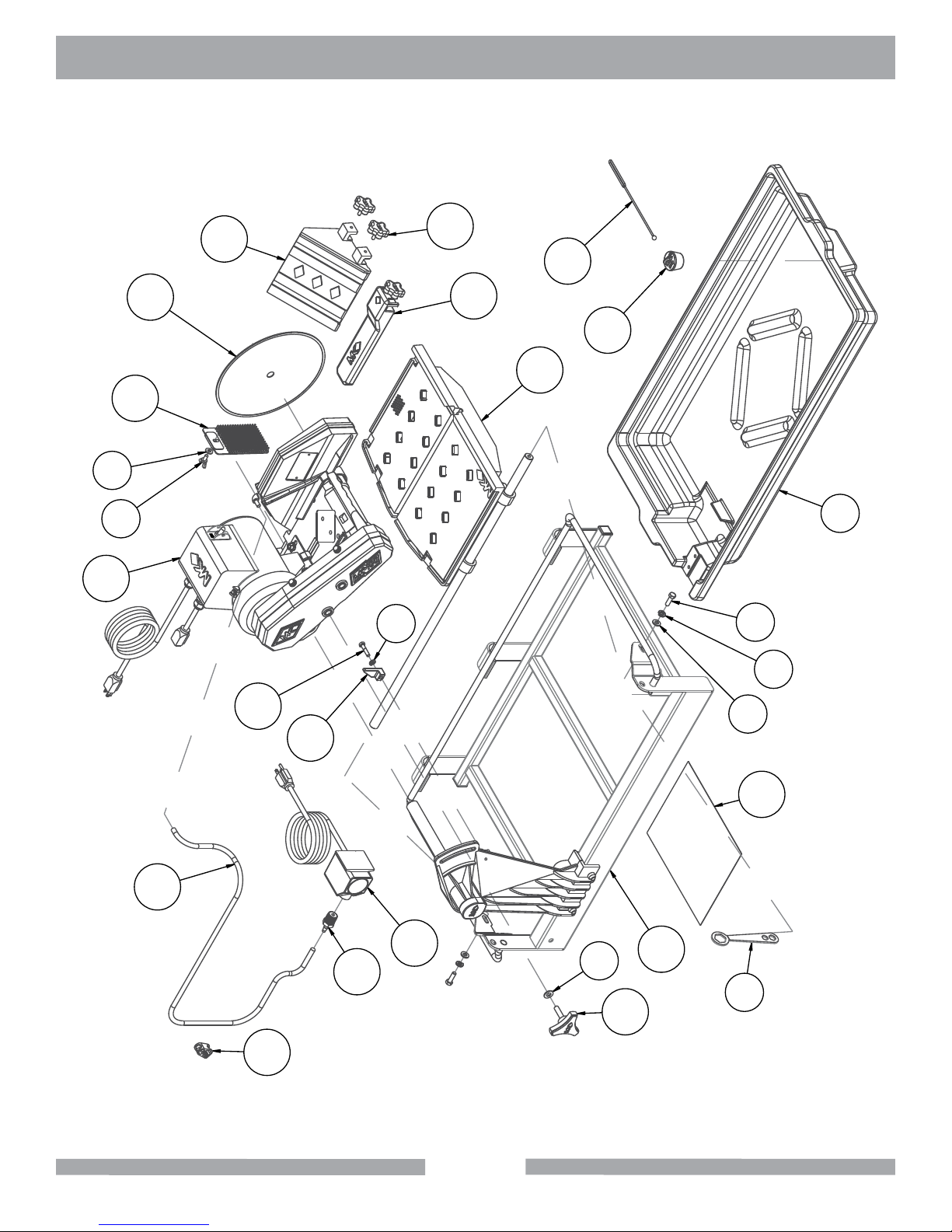
MK-100 Tile Saw Part # 158189
8
15
7
19
11
10
9
27
17
18
16
26
2
4
5
23
13
12
14
21
24
38
3
6
20
22
1
25
Page 39
MK-100 PARTS LIST
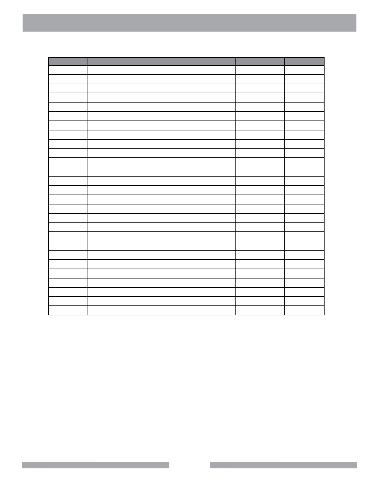
MK-100 Tile Saw Part # 158189
ITEM # DESCRIPTION PART # QTY.
1 WRENCH, TILE SAW NUT 15/16 134684 1
2 PAN, PLASTIC MK-101 150634 1
3 WASHER, FLAT, SAE, 3/8 150923 1
4 SCREW, HEX HD, 5/16-18X1 151743 2
5 WASHER, LOCK, SPLIT, 5/16 151747 2
6 WASHER, FLAT, SAE, 5/16 151754 2
7 SCREW, WING, 1/4-20X1/2 151888 1
8 WASHER, FLAT, SAE, 1/4 151915 1
9 WASHER, LOCK, SPLIT, 1/4 152591 1
10 CASTING, ACC BULLNOSE LRG-COMP 153201 1
11 MK-100 10X060X5/8 154380 1
12 CLAMP, HOSE, 1/4-1/2 FLOW 154394 1
13 SCREW, HEX HD, 1/4-20X1-1/4 157145 1
14 STOP, CUTTING HEAD 157728 1
15 ASSY, CUTTING HEAD, 100 158225 1
16 DRAIN PLUG, W/RING 159529 1
17 STRAP, 9" DRAIN PLUG 159530 1
18 RIP GUIDE, LARGE DIE CAST 159751 1
19 GUARD, SPLASH 160310 1
20 SHEET, WARNING LABLES, TILE SAW 166012 1
21 ADAPTER, 1/2 NPT X 1/4 BARB 168261 1
22 ASSY, FRAME & POST, 101 170476 1
23 HOSE, VINYL, 1/4X3/8 (6.0') 132951 1
24 PUMP, WATER 115V/60HZ UL/CSA 151271-VP 1
25 KNOB, TRI PLASTIC MK-660 1-1/2 156770-02 1
26 ASSY, DC TABLE, NO COVER, 101 158477-NC 1
27 KNOB, RUBBER, 1/4-20 X 3/4" LONG 159428-1 2
39
Page 40
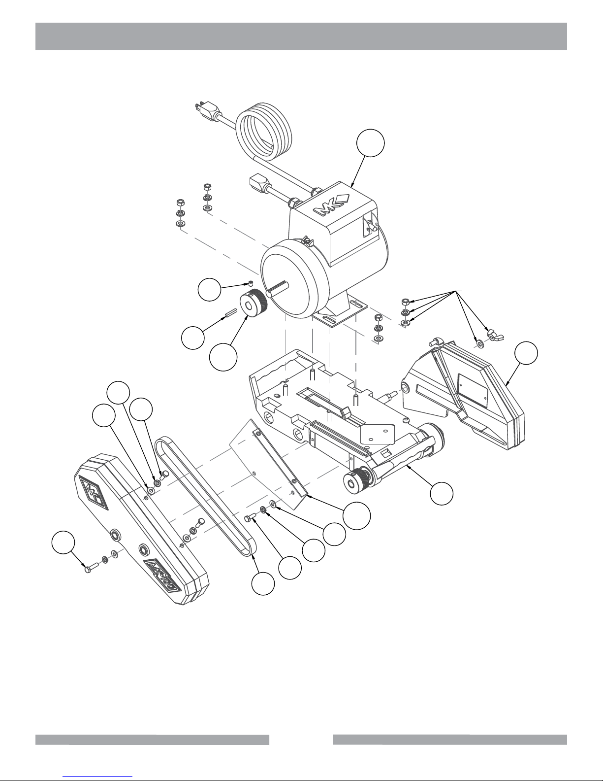
MK-100 EXPLODED VIEW
MK-100 Cutting Head Part # 158225
13
6
2
5
3
1
7
10
INCLUDED WITH ITEM 8
4
8
12
2
5
3
9
40
Page 41
MK-100 PARTS LIST
MK-100 Cutting Head Part # 158225
ITEM # DESCRIPTION PART # QTY.
1 KEY, 3/16 SQ X 1-1/8 150344 1
2 WASHER, FLAT, SAE, 1/4 151915 4
3 SCREW, HEX HD, 1/4-20X3/4 152370 3
4 ASSY, BLADE GUARD, 101 152582 1
5 WASHER, LOCK, SPLIT, 1/4 152591 4
6 SCREW, HEX HD, TAP, 1/4-20X1 152676 1
7 SCREW, 5/16-18 X 3/8 SOCKET HEAD SET 157083 1
8 ASSY, SUB, CTTG HD 101 158191 1
9 BELT, 6J260 158194 1
10 PULLEY, 6J19 X 5/8 BORE 158199 1
11 CASTING, 101 BELT GUARD -COMP 158319-00 1
12 BRACKET, INNER BELTGUARD 158611 1
13 MTR, 1-1/2HP, 115V, 3400 RPM 168022G 1
41
Page 42
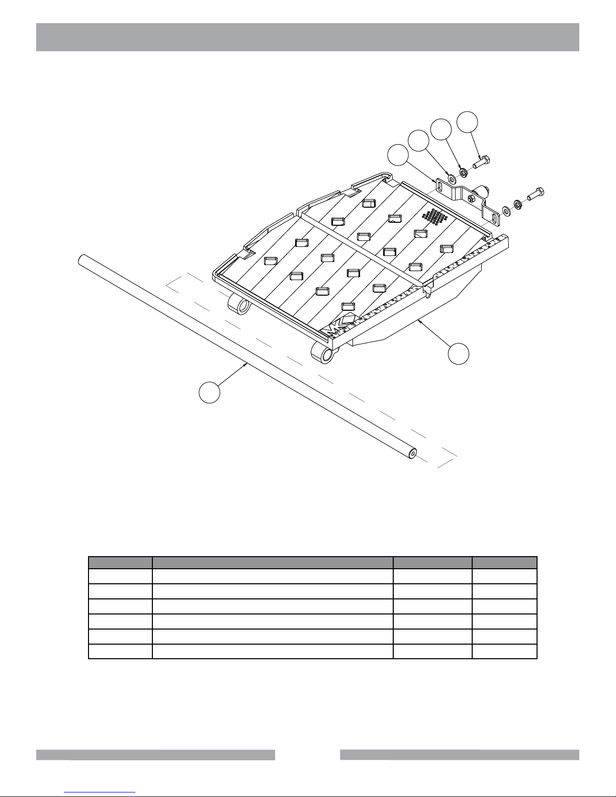
MK-100 EXPLODED VIEW & PARTS LIST
1
2
3
4
5
6
Assy, Table Part # 158477-NC
ITEM # DESCRIPTION PART # QTY.
1 BAR, GUIDE PLATED MK-101 134759 1
2 SCREW, HEX HD, 5/16-18X1 151743 2
3 WASHER, LOCK, SPLIT, 5/16 151747 2
4 WASHER, FLAT, SAE, 5/16 151754 2
5 ASSY, WHEEL BRKT TSAW 151756 1
6 CASTING, TABLE MK-100 COMP 157660 1
42
Page 43
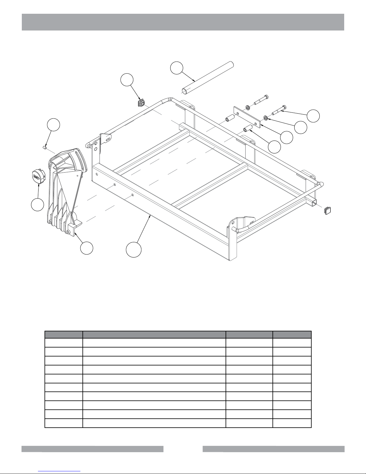
MK-100 EXPLODED VIEW & PARTS LIST
Assy, Table Part # 170476
2
9
5
3
8
1
4
7
6
10
ITEM # DESCRIPTION PART # QTY.
1 WASHER, LOCK, SPLIT, 3/8 150925 2
2 SHAFT, 10.63 PIVOT 153254 1
3 SCREW, SET, SOC, CUPT, 3/8-16X1/2 153710 1
4 PLATE, PRESSURE 155671 1
5 SCREW, 3/8-`16 X 2-1/2 HEX HEAD CAP 156030 2
6 CASTING, POST, DC, 101, MKRED-COMP 158438 1
7 POST COVER, PLASTIC 160157 1
8 SPACER, 5/8 X .385 X 1.4 160654 2
9 PLUG, PLASTIC, 1 SQ-14-20 GA 160727-1 2
10 FRAME, 10" TILE SAW, 18" RIP 168021 1
43
Page 44
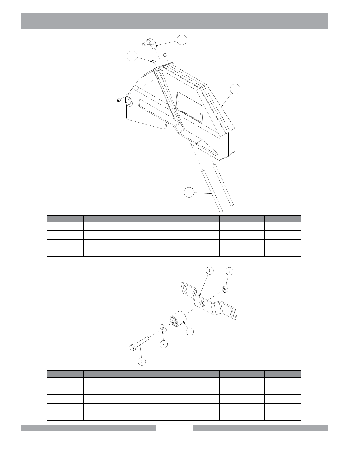
MK-100 EXPLODED VIEW & PARTS LIST
2
Blade Guard
Part# 152582
1
4
3
ITEM # DESCRIPTION PART # QTY.
1 SCREW, 5/16 - 18 X 1/2 SOCKET HD SET 152607 3
2 ELBOW, 1/2MNPT X 1/4 BARB, 90 DEG 154652 1
3 TUBE, WATER 155389 2
4 CASTING, 101 BLD GUARD-DC-COMP 162481 1
Roller Wheel Assembly Part # 151756
ITEM # DESCRIPTION PART # QTY.
1 WHEEL, ROLLER 151799 1
2 NUT, HEX, 1/4-20 151893 1
3 SCREW, HEX HEAD 1/4-20 X 1-12" 151914 1
4 WASHER, 1/4 SAE FLAT 151915 1
5 BRACKET, ROLLER WHEEL 154021 1
44
Page 45
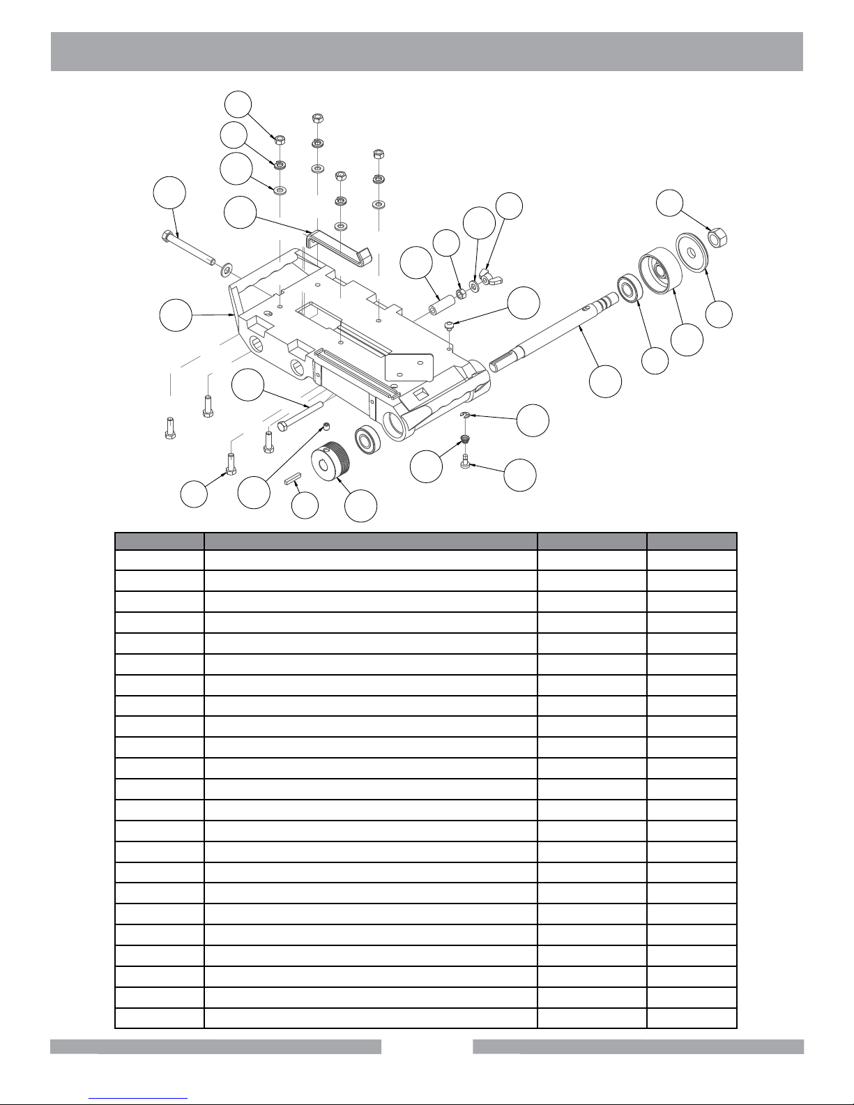
MK-100 EXPLODED VIEW & PARTS LIST
1
9
10
Table Assembly
Part# 158191
13
20
11
1
23
21
17
7
14
5
15
8
10
12
19
18
16
3
22
4
ITEM # DESCRIPTION PART # QTY.
1 NUT, HEX, 5/16 - 18 101196 5
2 FLANGE, OUTER, 2 - 3/8 135830 1
3 NUT, HEX, 5/8-18 135848 1
4 BEARING, BALL, 17X40X12MM 137711 2
5 KEY, 3/16 SQ X 1-1/8 150344 1
6 WASHER, FLAT, SAE, 3/8 150923 1
7 SCREW, HEX HD, 5/16-18X1 151743 4
8 NUT, WING, NYLK, 5/16-18 151746 1
9 WASHER, LOCK, SPLIT, 5/16 151747 4
10 WASHER, FLAT, SAE, 5/16 151754 5
11 STRAP, 1 INCH, MOTOR ADJ. 152673 1
12 BUMPER, RUBBER, 1/2 DIA 152674 1
13 BOLT, 3/8-16 X 3-1/2 HEX HEAD TAP 153147 1
14 SCREW, 5/16-18 X 3/8 SOCKET HEAD SET 157083 1
15 PULLEY, 6J19 X 5/8 BORE 158199 1
16 BUTTON, SHAFT LOCK 158200 1
17 SPRING, BLADE SHAFT LOCK 158201 1
18 RING, 1/4 E-STYLE RETAINING 158202 1
19 SHAFT, BLADE 158222 1
20 CASTING, 10” CTTG HEAD - COMP 158224 1
21 SCREW, HEX HD, TAP, 5/16-18X3 162473 1
22 FLANGE, Ø 2-3/8 INNER 162758 1
23 SPACER, 9/16X5/16X1.5, PLAS 170824 1
2
45
Page 46

MK-100 TILE SAW THEORY
THEORY OF DIAMOND BLADES
Diamond blades do not really cut; they grind the material through friction. Diamond crystals, often
visible at the leading edge and sides of the rim/segment, remove material by scratching out particles of hard, dense materials, or by knocking out larger particles of loosely bonded abrasive material. This process eventually cracks or fractures the diamond particle, breaking it down into smaller
pieces. As a result, a diamond blade for cutting soft, abrasive material must have a hard metal
matrix composition to resist this erosion long enough for the exposed diamonds to be properly utilized. Conversely, a blade for cutting a hard, non-abrasive material must have a soft bond to ensure
that it will erode and expose the diamonds embedded in the matrix. These simple principles are the
foundation of “controlled bond erosion”
Types of Cutting
There are two basic types of cutting-Dry or Wet. The choice of which type of blade to use
depends on:
• The requirements of the job
• The machine/tool utilizing the Diamond Blade
• The preference of the operator
In the case of DRY cutting, the overwhelming popularity and quantity of hand-held saws and the
exible nature of MK Diamond blades to professionally handle most ceramic, masonry, stone and
concrete materials, make the DRY cutting blade a very attractive tool. When using a DRY blade,
the user must be aware of distinct operating practices to ensure optimum performance. DRY cutting
blades require sufcient airow about the blade to prevent overheating of the steel core. This is best
accomplished by shallow, intermittent cuts of the material with periods of “free-spinning” (for several
seconds) between each cut, to maximize the cooling process.
For WET cutting applications, MK has the exact blade to compliment both the material to be cut and
the wet cutting machine to be used. During cutting operations, liberal amounts of water act as a
coolant to support the cutting effectiveness and longevity of the WET blade. Additionally, using water
adds to the overall safety of cutting operations by keeping the dust signature down.
KNOW ALL YOU CAN ABOUT THE MATERIAL YOU WISH TO CUT
46
Page 47
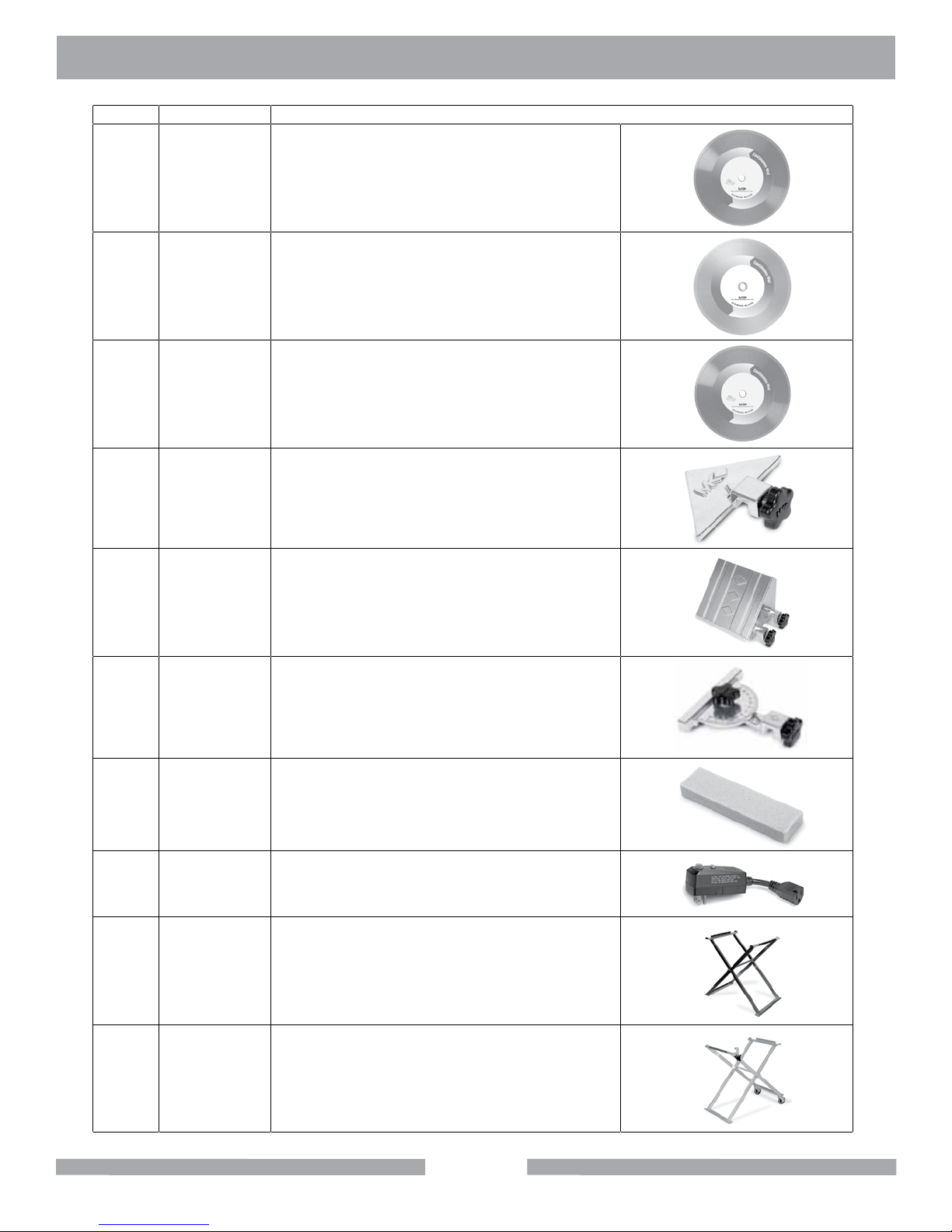
MK-10O TILE SAW ACCESSORIES
ITEM NUMBER DESCRIPTION
1.
2.
3.
134577-MK
4.
5.
153201-MK
137166
128074
153252
MK-200, 10 x 5/8 Arbor
Premium grade Diamond Blade for
smooth, chip-free cutting on tile.
MK-215, 10 x 5/8 Arbor
Supreme grade diamond blade for hard
materials
MK-315, 10 x 5/8 Arbor
Supreme super hi-rim diamond blade
Dual 45° Flat Angle Guide
45° Bullnose Miter
6.
134569-MK
7.
8.
9.
10.
152792
152610
168244
169243
90° Protractor
Dressing Stone
Ground Fault Circuit Interrupter
Folding Stand
Folding Stand with Casters
47
Page 48
MK-100 TILE SAW ORDERING & RETURN
ORDERING INFORMATION
You may order MK Diamond products through your local MK Diamond distributor or, you may order
direct from MK Diamond.
When ordering direct from MK Diamond, please have the following information ready before calling:
• The Model Number of the saw
• The Serial Number of the saw
• Where the saw was purchased and when
• The Part Number for the part(s) being ordered
• The Part Description for the part(s) being ordered
NOTE: There is a $25.00 minimum order when ordering direct from MK Diamond. A $6.00 charge will
be added to orders having a net billing value under $50.00. All purchases must be made using VISA,
MasterCard or American Express.
All parts may be ordered by calling toll free to – 800 421-5830 or 310 539-5221 and asking for
Customer Service. For technical questions, call – 800 474-5594.
RETURN MATERIALS POLICY
To expedite the service relative to the return of a product purchased through MK Diamond, please
observe the following:
NOTE: When returning all items, they must have been purchased within the previous twelve (12)
months.
• Have the Model Number of the saw
• Have the Serial Number of the saw
• Have the location of where the saw was purchased
• Have the date when the saw was purchased
• Contact Customer Service for approval to return the item(s)
• Obtain a Returned Goods Number (RGA) authorizing the return
• Follow the packaging instructions in the following section
• Ensure your item(s) are prepaid to the destination
For returned items, call toll free to – 800 421-5830 or 310 539-5221 and ask for Customer Service.
For technical questions, call – 800 474-5594 or 310 257-2845.
PACKAGING INSTRUCTIONS
• Remove the Cutting Head and Support Angle Assembly
• Dry the saw before shipping
• When packing, include the following: Saw, Diamond Blade, Blade Guard and Support Angle
Assembly and Adjustable Cutting Guide (Other Accessories are not required)
• Package the unit in its original container or one of comparable size (do not ship the unit partially
exposed)
• Ensure all parts are secured in the packaging to prevent moving
AUTHORIzED SERVICE CENTERS
For quicker repair time, you may contact MK Diamond Customer Service, toll free, at 800 421-5830
or 310 539-5221 for the Authorized Service Center closest too you or visit our web site at
www.mkdiamond.com. For technical questions, call – 800 474-5594.
48
Page 49

MK-100 TILE SAW CONTACT & WARRANTY
CONTACT:
Please contact MK Diamond Products, Inc. Customer Service Department with any questions you
might have regarding distributors, parts or service.
Telephone: (800) 421-5830
Fax: (310) 539-5158
E-mail: [email protected]
Customer Service Hours: Monday through Friday, 6AM-4PM PST
MK Diamond Products, Inc.
1315 Storm Parkway
Torrance, CA 90501
MK DIAMOND PRODUCTS, INC. LIMITED WARRANTY
MK DIAMOND PRODUCTS, INC. will guarantee every machine they build, to be free from defects in
material and workmanship for (1) one year from date of purchase. The obligation of MK DIAMOND
PRODUCTS, INC. under this warranty is limited to the repair or replacement of any parts which,
under normal use, prove to be defective in material or workmanship. The parts involved or the unit
in question should be returned to MK DIAMOND PRODUCTS, INC. or to a point designated by us,
transportation prepaid.
This warranty does not obligate us to bear the cost of labor or transportation charges in connection
with replacement or repair of defective parts. Likewise, it shall NOT apply to any unit which has been
subjected to misuse, neglect or accident. This warranty does NOT apply to any machine which has
been repaired or altered outside our factory.
This warranty does NOT obligate MK DIAMOND PRODUCTS, INC., with respect to items not of our
manufacture, such as engines, motors, hydraulics, etc., which are subject to their own guarantees and
warranties.
We shall in no event be liable for consequential damages or contingent liabilities arising out of failure
of any equipment or parts to operate properly.
© COPYRIGHT 2014, MK DIAMOND PRODUCTS, INC. ALL RIGHTS RESERVED.
The MK Diamond logo is a registered trademark of MK Diamond Products, Inc. and may not be used,
reproduced, or altered without written permission. All other trademarks are the property of their respective owners and used with permission.
MK Diamond may have patents, patent applications, trade marks, copyrights of other intellectual
property right covering this product in this document.
This manual MUST accompany the equipment at all times. This manual is considered a permanent
part of the equipment and should remain with the unit if resold.
The information and specications included in this publication were in effect at the time of approval for
printing.
49
Page 50

NOTES
50
Page 51

NOTES
51
Page 52
MK-100 TILE SAW
OWNER'S MANUAL & OPERATING INSTRUCTIONS
MK Diamond Products, Inc.
1315 Storm Parkway
Torrance, CA 90501
Toll-Free: (800) 421-5830
Phone: (310) 539-5221
Fax: (310) 539-5158
www.mkdiamond.com
 Loading...