

MJM Yachts LLC 40z Owner's Manual

40z Owners Guide

“Believe me, my young friend, said the water rat solemnly, there is
nothing, absolutely nothing, half so much worth doing as simply
messing about in boats. Simply messing...nothing seems really to
matter. That's the charm of it. Whether you get away, or whether you
don't, whether you arrive at your destination or whether you reach
somewhere else, or whether you never get anywhere at all, you're
always busy, and you never do anything in particular...”
…The Wind in the Willows by Kenneth Grahame

Dear 40z Owner
Congratulations on becoming an owner of an MJM 40z. We’re dedicated to making it the
world’s best in class. As you read this guide and share cruising adventures, we hope you’ll
discover our mission has been accomplished.
MJMs are made of epoxy, Kevlar, Eglass and Corecell. They are the most fuel-efficient
yachts of their size by a wide margin. We’ve set the quality bar on the top rung in selecting
our equipment suppliers and cabinetmakers. It’s one of only two 40-footers certified ISO
Category A Ocean, the highest rating achievable for seaworthiness. It leads the boating
industry with the most advanced technology. Standard MJM 40z specifications are unusually
complete in terms of equipment and amenities. The boats are safe, reliable, easy to handle
by one person, and are high performers. Last but not least, and our number 1 design
mandate, they’re beautiful.
Primary to this Owners Guide, and in terms of authority, are two large binders with equipment
supplier owner manuals and warranties. These documents contain an enormous amount of
important information. Please keep them accessible for reference when you have an issue or
question not covered in detail by this guide. You can download most of them from their
websites for an iPad and install them on the Raymarine display.
This guide reflects our experience from building over 200 MJMs. I personally have spent
more than 6000 hours cruising on MJM yachts so I wanted to impart some advice and
background information along with the “how to do it.” You will see these comments in the
blue sidebars.
As you enjoy your new boat, remember that much of the equipment contains computer
chips that can sometime have glitches that can be corrected with a re-boot. With proper
safety precautions and good weather planning, I’m sure you will spend many enjoyable hours
on your new yacht.
Robert I. Johnstone
Founder and CEO
(401) 862-4367
bob@mjmyachts.com


QUICK START GUIDE
Following is a departure checklist for an experienced captain who is familiar with the information in this
guide and the accompanying binders.
Check Systems
☐ Check ENGINE and GENERATOR raw water strainers (a flashlight is helpful to see into the strainers),
seacocks, coolant, engine oil and drive oil. (See Daily Engine Check, page 6.) Look for loose belts,
wires, oil drips and bilge water.
☐ Check
SEAKEEPER and AIR CONDITIONING raw water strainers.
Get Set
☐ Turn off the SHORE 1 and SHORE 2 breakers at the 120V AC panel. Then do 1 or 2 below.
1. If you plan to use the GENERATOR underway to power the SEAKEEPER or the AIR CONDITIONER,
s
tart the GENERATOR. (See page 22.) Start the SEAKEEPER. (See page 29.)
2. If don’t plan to use the GENERATOR underway, turn on the INVERTER/CHARGER to provide power to
120V AC circuits. (See page 25.)
☐ With the HOUSE BATTERY switch on, ensure at least 12.2V. Turn on TRIM TABS, ELECTRONICS,
HORN, WIPERS and other breakers for equipment you anticipate using, such as NAVIGATION LIGHTS
and
SEARCHLIGHT.
☐ Turn
off breakers at shore side power pedestal first, then disconnect shore power cord, phone, TV
and dock water if connected, Screw caps in place, close shore power cover and stow cables.
Get Underway
☐ Turn on ENGINE BATTERY switches at the top of the 120V AC panel. At the helm push the IGNITION
BUTTON for each engine (it lights up). Wait until the Volvo Penta ENGINE CONTROL DISPLAY shows
gauges, start
ENGINES by pressing the START/STOP buttons under the IGNITION buttons. (See page
8.)
Ensure people, equipment, lines and hoses aren’t in the water and everything is clear of
moving parts before you start the engine.
☐ At the top of the Raymarine screen (if set up) drag down the supplementary data bar showing RPM,
coolant temperature, oil pressure, drive oil pressure and nmpg fuel efficiency.
If voltage is too low to crank the engines, see Starting with Low Batteries, page 38.
If the battery is low, you should not leave the dock until you diagnose and correct the
problem.
☐ Check the Plexiglas top of the raw water strainers above the engines to ensure that raw water is
flowing.
☐ Check
IPS JOYSTICK. Push lower left DOCKING button and listen for a confirming beep. Test
operation with a slight tap in any direction. Check that the steering turns smoothly. Check
TRIM TAB
function and set for planing speeds under 25 knots (60% with two people aboard).
☐ Check fuel levels, oil temperature and oil pressure. (See Operating Parameters, page 9.)
☐ If everything is in order, cast off dock lines. When maneuvering with the
IPS JOYSTICK, a light touch
(taps and nudges) on the joystick is usually the most effective.
Confirm that no one is on the foredeck or in the water.

CE CERTIFICATION
CERTIFICATE NO.
BBBW003
AUTHORITY: ADDRESS:
International Marine Certification Institute
Rue Abbe Cuypers 3
B-1040 Bruxelles. Belgique
PHONE
+32-2-741-2418
WEBSITE
www.imci.org
CLASSIFICATION
ISO CE Mark Design Category A Ocean (EC Directive 94/25/EC)
for craft designed for offshore voyages (1) where the vessel is
correctly handled in the sense of good seamanship and operated
at a speed appropriate to the prevailing sea state and (2) with
significant wave heights above 4 m (calculations are based on 7
m) and wind speeds in excess of Beaufort Force 8, but excluding
abnormal conditions, e.g. hurricanes.
CAPACITY
PERSONS
Maximum 16 Persons
PERSONS/GEAR
Maximum Load 3518 kg
RECEIPT BY OWNER In compliance with ISO 10240:1995(E) the owner hereby certifies receipt
of this manual and has read and agrees to the terms of the Builder’s Limited Warranty included
herein.
NAME
Signature
Printed Name(s) and Date
BOAT
Boat Name and Hull Number
CONTACT INFORMATI0N
Street Address
City, State, Zip
Mobile Phone
e-Mail
Please sign one of the two copies of this page and return it in the attached stamped envelope to MJM
Yachts, 39 Washington Street.
Newport,
RI 02840.

TABLE OF CONTENTS
1! INTRODUCTION 1!
1.1! Purpose and Limitations ......................... 1!
1.2! Standard Specifications ......................... 1!
1.3! Conventions ......................................... 1!
2! SAFETY and some USCG REQUIREMENTS 2!
2.1! Binder Manuals ..................................... 2!
2.2! Standard Equipment .............................. 2!
2.3! Commissioning Package Safety Items ..... 3!
2.4! USCG required equipment ..................... 3!
2.5! Additional Safety Equipment ................... 3!
2.6! Some Additional USCG Requirements .... 3!
2.7! Fuel Shut-off Valves .............................. 4!
2.8! Fire Suppression ................................... 4!
2.9! Notices ................................................ 4!
2.10! Emergency and Thru Hull Diagram .......... 5!
3! PROPULSION 6!
3.1! Engines ................................................ 6!
3.2! Daily Engine Check ............................... 6!
3.3! Starting the Engines .............................. 8!
3.4! Stopping the Engines ............................ 9!
3.5! New Engine Break-in ............................. 9!
3.6! Auxiliary Stop ........................................ 9!
3.7! Operating Parameters ............................ 9!
3.8! Leaving the Boat ................................. 10!
3.9! Volvo Penta D6 IPS Engines ................. 11!
4! INSTRUMENTS AND CONTROLS 12!
4.1! Helm Station ....................................... 12!
4.2! Engine/Shift Control Levers .................. 12!
4.3! Joystick .............................................. 13!
4.4! Electronics ......................................... 14!
4.5! Compass Heading and Calibration ........ 15!
4.6! Trim Tabs ........................................... 15!
4.7! Searchlight ......................................... 15!
4.8! Autopilot ............................................. 16!
4.9! Single Engine Steering ......................... 16!
4.10! MultiFunction Dislay (MFD) ................... 16!
4.11! Console Switch Panel ......................... 16!
4.12! Windshield Operation .......................... 17!
5! ELECTRICAL SYSTEMS 18!
5.1!
Electrical Safety
................................. 18!
5.2! Electrical Power .................................. 18!
5.3! Shore Power ....................................... 19!
5.4! Fuse Locatons .................................... 19!
5.5! 24-Hour Circuits ................................. 19!
5.6! The 12V DC Panel ............................... 20!
5.7! The 120V AC Panel ............................. 21!
5.8! Northern Lights Generator (O p t i o n ) ..... 22!
5.9! Corrosion Protection ............................ 23!
5.10! Generator Component Locations .......... 24
5.11! Victron Inverter/Charger ....................... 25!
5.12! Bonding ............................................. 25!
6! WATER SYSTEMS 26!
6.1! Fresh Water ........................................ 26!
6.2! Hot Water ........................................... 26!
6.3! Gray Water ......................................... 27!
6.4! Raw Water .......................................... 28!
7! SEAKEEPER GYROSTABILIZER (Option) 29!
7.1! To Start the Gyro ................................ 29!
7.2! Activate/De-activate ............................ 29!
8! EQUIPMENT, APPLIANCES and FINISHES 30!
8.1! Anchor Windlass ................................. 30!
8.2! Anchor Washdown .............................. 30!
8.3! Fusion Multi-media Player .................... 30!
8.4! Privacy/Sunscreen Curtains (Option) ..... 31!
8.5! Transom Door and Seat (Option) .......... 31!
8.6! Vacuum Cleaner ................................. 31!
8.7! Cooktop ............................................. 32!
8.8! Microwave .......................................... 32!
8.9! Refrigerator ......................................... 32!
8.10! Freezer .............................................. 32!
8.11! TVs (optional) ...................................... 32!
8.12! Vacuum Flush Head System ................ 33!
8.13! Air Conditioning (Optional) ................... 33!
8.14! Finishes ............................................. 34!
9! APPENDIX 35!
9.1! The Top 10 Causes of Engine Failure .... 35!
9.2! Diesel Operation ................................. 36!
9.3! Starting with Low Batteries ................... 38!
9.4! Winter Storage .................................... 39!
9.5! Spring Commissioning ......................... 40!
9.6! Hauling Out and Blocking ..................... 40!
9.7! Trailer Loading Checklist ...................... 40!
9.8! Fuel Consumption ............................... 41!
9.9! Routine Maintenance ........................... 42!
9.10! Boat Lift and Bunk Offsets ................... 43!
9.11! Systems Location Plan ........................ 44!
9.12! Systems Key ...................................... 45!
9.13! Wiring Diagrams ................................. 46!
9.14! Fuse Locations & Specifications ........... 47!
9.15! Fuel Consumption Log. ....................... 48!
9.16! Boston Boatworks Limited Warranty ..... 49!
10!THE MJM TEAM 53!
10.1! Bob Johnstone ................................... 53!
10.2! Chris Hughes ..................................... 53!
10.3! Doug Zurn .......................................... 53!
10.4! Scott Smith ........................................ 54!
10.5! Mark Lindsay ..................................... 54!
10.6! Steve Burke ....................................... 54!

MJM 40z
LOA: Length overall
including
swim
platform
& bow roller (LOA) ......... 44.3
ft.
LOD: Length on deck (LOD ................................................................. 40.0 ft.
Beam (Maximum width on trailer) ......................................................... 12.0 ft.
Maximum Trailer weight ................................................................ 21,800 lbs.
Draft with IPS pod drives ...................................................................... 3.3 ft.
Displacement (½ load) ................................................................. 18,900 lbs.
Fuel tankage (two 175 gallon tanks) ................................................... 350 gal.
Fresh water tankage (including hot water tank) .................................... 112 gal.
Holding tank ...................................................................................... 25 gal.
Air height above water to top of radar dome mounted on hard top ....... 10.0 ft.

Chapter 1, Introduction, MJM 40z Owner’s Manual page 1
1 INTRODUCTION
1.1 PURPOSE AND LIMITATIONS
This purpose of this Owners Guide and the equipment suppliers’ manuals in
the accompanying binders is to provide you with an overview of the yacht’s
equipment, operation, systems and maintenance. The people at MJM and
Boston Boat Works have taken pains to edit this guide for accuracy in good
faith. But most of these topics will require further study and learning. As captain
of a vessel you assume extensive responsibilities for safe operations and the
safety of your crew.
No document that intends to cover yacht equipment and operation will ever be
complete or even accurate in all respects. Since we frequently make changes
to improve our yachts we assume no responsibility for missing information or
errors in the following information. This document doesn’t replace common
sense or qualify you in safety practices, boat handling or navigation skills.
Mastering these systems and the skills of seamanship is your responsibility. If
this is your first yacht, or if you’re changing from a different type of yacht, get
instruction and experience before assuming command. Your dealer, yacht club,
marina or the US Power Squadron https://www.usps.org are all good
resources that can recommend schools and instruction.
Although this guide and the accompanying binders describe systems on the
boat, they don’t qualify you to work on them. When they need attention, please
use qualified mechanics. If you question the information or are unsure about an
action, check with the equipment supplier, a qualified person or us.
The Appendix includes other useful information. And there’s a chapter on the
people who create MJM yachts you can contact if you need help. Study these
resources to understand how to operate your yacht safely.
The operation of a powerboat can be dangerous. Pay careful
attention to safety notices in this guide and in the manuals in the binders.
Keep this guide in a secure place on the boat. If you sell the yacht, please give
this copy to the new owner.
1.2 STANDARD SPECIFICATIONS
You may download the latest version of this guide and the standard
specifications for a MJM40z from http://www.mjmyachts.com/40z to install on
your computer, an iPad or navigation electronics.
1.3 CONVENTIONS
When we reference a specific device or item of equipment on the boat, it will
be in all caps, such as
HOUSE BATTERY.
As we describe each device we often use the following order.
1.
BREAKER PANEL settings
2. Function, what it does
3. Directions for use
4. Advice or comments in a sidebar
5. The URL for the manual if available
This guide is published in accordance
with ISO standard 10240:1995E Small
Craft - Owner’s Manual.
Please contact us if you have a question
about the material in this book, if you find
a conflict between this material and the
material in the binders or if you find an
error or important omission on the
following pages please contact
Customer Service at Boston Boat
Works.
…R.I.J.

Chapter 2. Safety, MJM 40z Owner’s Guide page 2
2 SAFETY and some USCG REQUIREMENTS
2.1 BINDER MANUALS
The equipment suppliers’ manuals in the accompanying binders have many
safety notices that relate to their products, their operation and maintenance and
their use in the boat. Ensure that you understand this essential information
before you operate the boat. Spend time reviewing the safety procedures, how
safety equipment works and where It’s stowed. Instruct guests in safety
procedures.
2.2 STANDARD EQUIPMENT
VHF Radio BREAKER PANEL settings: ELECTRONICS breaker on. The VHF RADIO
may be used for receiving weather broadcasts, communicating with harbors,
locks (ch13), bridges (ch 9), marinas, the U.S. Coast Guard (USCG), rescue
services boats and other boats. The USCG monitors channel 16. If you normally
have your radio tuned to channel 16 you can listen for emergency calls from
nearby boats or be able to make an emergency call quickly. Don’t use Channel
16 for a private conversation.
MMSI Number The radio has Digital Selective Calling (DSC). It’s arguably the
most important piece of safety equipment on the boat. There’s a one-button
emergency transmit button that sends a Maritime Mobile Service Identity (MMSI)
number to the USCG. The signal identifies the boat. It’s interfaced with GPS so
your position will be sent with the emergency message. The Automatic
Identification System (AIS) will report your MMSI number to other vessels and
you will see their MMSI number. If you sell your boat, the
MMSI number is
normally transferred with it but the new owner should update the information.
In addition to the safety function, an
MMSI number is like a phone number. You
can make a call to another
DSC-equipped vessel if you know its MMSI number.
Only the vessel being called will receive the hail.
BoatUS http://www.boatus.com/MMSI/ is authorized by the Federal
Communications Commission and the USCG to assign MMSI numbers. The
Installation and Operation Instructions for the
VHF RADIO included in the binder
explains how to install the MMSI number in your radio. It also explains how to
use the
VHF RADIO. It may be downloaded at:
https://raymarine.app.box.com/s/grwg60669c5sozf6iolq/1/2757682985
The Horn BREAKER PANEL settings: HORN breaker on. The USCG requires a
“Sound Producing Device” for signals under many circumstances. The HORN is
operated from a switch on the
CONSOLE SWITCH PANEL at the helm. The
adjacent
UNDERWAY HORN/ANCHOR switch has programmed signals. (See
page 16.)
Electronics fail. It’s wise to have a portable VHF radio, GPS receiver,
SEARCHLIGHT and HORN that are battery operated and hand held.
Fire Extinguishers See EMERGENCY DIAGRAM page 5 for Fire Extinguisher
locations when the boat is delivered.
Carbon Monoxide Detector See EMERGENCY DIAGRAM page 5.
To send a distress call (without
specifying its nature) press and hold the
red distress
key for 3 seconds. See
Ray218E/Ray55E Installation and
Operation Instructions.

Chapter 2. Safety, MJM 40z Owner’s Guide page 3
Companionway Hatch Board or Closure A companionway board with the label
“DON’T REMOVE WHILE UNDERWAY” is provided to comply with ISO requirements
for cockpit draining and to prevent large waves from crashing down into the
cockpit, running forward and entering the interior of the boat if the
companionway door is not securely closed.
2.3 COMMISSIONING PACKAGE SAFETY ITEMS
The Commissioning Package Option, if purchased with your boat, will have:
• A copy of the U.S. Department of Homeland Security United States Coast
Guard Navigation Rules to be on board. It also may be downloaded at:
http://www.navcen.uscg.gov/pdf/navrules/navrules.pdf
• A First Aid Kit
• Sixteen wearable USCG approved personal flotation devices (life-jackets)
and one type IV throwable PFD
• A 12-Gauge Flare Kit
• A Hand-held Bilge Pump
• A Hand-held LED Flashlight
• Paper Charts
2.4 USCG REQUIRED EQUIPMENT
A Boater’s Guide to the Federal Requirements for Recreational Boats, published
by the USCG, lists required safety items. The Guide may be downloaded at:
http://www.uscgboating.org/images/420.PDF. Check state regulations where
you cruise for other requirements.
2.5 ADDITIONAL SAFETY EQUIPMENT
There are many other items of safety equipment to consider such as:
EPIRB (Emergency Position Indicating Radio Beacon) alerts search and rescue
services by transmitting a coded message and is detectable by satellite
anywhere in the world. Although the USCG doesn’t require them, EPIRBs are
essential offshore and desirable anywhere.
Inflatable Life Raft isn’t required but prudent. Rafts come in compact sizes that
can be stored in a cockpit locker. A dinghy isn’t a substitute for a life raft.
Heaving Line is handy to have for emergency or to simply trail behind the boat (if
the engines are off) attached to one of the stern cleats when people are
swimming. Polypropylene is good because it floats.
A Storm Anchor is useful as a back up and for situations when two anchors are
prudent or necessary.
2.6 SOME ADDITIONAL USCG REQUIREMENTS
In addition to the above safety equipment, the USCG requires:
Ships Registration and Documentation Carry the Vessel Registration, either the
state-issued Certificate of Number or Vessel Documentation if federally
documented with the USCG. It’s wise to have your insurance as well.
Pollution Regulation Plaques You are required to post three visible placards in
the boat that stipulate that waste must be managed; that oil discharge is
prohibited and deposit of any refuse matter of any kind into the waters of the US
is prohibited. West Marine has such plastic placards with adhesive backs that
are available at little or no cost.
Better to just secure the companionway
slider and lid. It’s quieter, prevents
someone from being pitched below and
provides a Chart Kit navigation surface.
---R.I.J.

Chapter 2. Safety, MJM 40z Owner’s Guide page 4
2.7 FUEL SHUT-OFF VALVES
The first thing to do if there is a fuel fire or leak is stop engines and close fuel
shut-off valves by turning them perpendicular to the hose. They are located over
the fuel tanks under the pilothouse seats. If there is fuel in the bilges, close
valves, find the source of the leak and then clean bilges.
2.8 FIRE SUPPRESSION
An automatic, heat-activated, fire suppression system is installed in the engine
compartment. It can be activated manually at the helm station. To prevent the
engines from evacuating the fire suppression agent when it discharges, the
system will shut off engines, blowers and generator. Override the shutdown
feature to restart the engine after repair. Refer to the manual for maintenance
instruction. (See page 12 and refer to the manual in the binders.)
Hand-held fire extinguishers (see Emergency Diagram page 5 for locations) are
rated to fight type A, B & C fires. To extinguish a fire, first cut the source of fuel
to the fire. In a diesel fuel fire, turn off the fuel tank valves. In an electrical fire, turn
off the HOUSE BATTERY switch.
Fire safety begins with prevention. Reduce fire risk with these guidelines:
• Don’t allow debris or oily rags to collect anywhere.
• Check bilges for oil or diesel fuel regularly.
• Shut down unnecessary circuits when leaving the boat.
• Don’t leave heat-producing appliances or equipment unattended.
• Inspect fire suppression equipment regularly and learn how to use it.
Exhaust gas contains carbon monoxide. It’s colorless, odorless and
lethal. Avoid inhaling. Inspect the exhaust system regularly. Idling engines at a
mooring or at a dock isn’t good for the engine and may allow gasses to
accumulate in the cockpit or cabin.
Don’t work on any mechanical or electrical equipment unless you’re
qualified. Electrical current and moving parts are dangerous and can be lethal.
2.9 NOTICES
Denotes a reminder of safety practices or directs attention to unsafe
practices which could result in personal injury or damage to the craft or
components.
Denotes a hazard that exists which can result in injury or death if
proper precautions aren’t taken.
Denotes an existing extreme intrinsic hazard that would result in high
probability of death or irreparable injury if proper precautions aren’t taken.
Starboard FUEL SHUT OFF
Port FUEL and GENERATOR FUEL
SHUT OFF
FIRE SUPPRESSION system and stern
BILGE PUMP
Fire needs oxygen to burn, so if a fire
should occur in an enclosed area, the
best course of action may be to exit the
area and seal it from the outside by
closing means of air intake.
…R.I.J.
Chapter 2. Safety, MJM 40z Owner’s Guide page 5
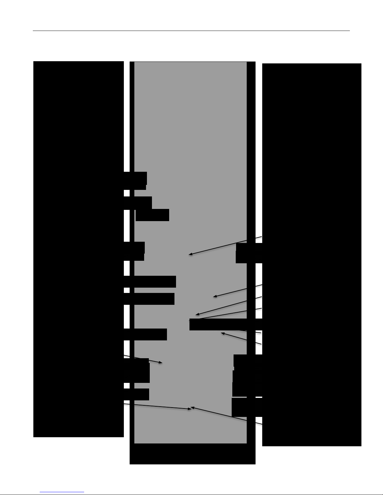
2.10 EMERGENCY AND THRU HULL DIAGRAM
Sink Thru Hull
Sump Pump Thru Hull
First Aid Kit
Sink Thru Hull
Manual Bilge Thru Hull
Manual Bilge Pump
Seakeeper Raw Water Intake
Fuel Shut-off Valve on Tank
Shore Power Breakers
Seakeeper Thru Hull
Deck Drain Thru Hull
Waste Discharge Thru Hull
Engine Room SeaFire
Electric Bilge Pump 1
Bilge 1 Thru Hull
AC Thru Hull
AC Raw Water Intake
Systems Room SeaFire
Generator Raw Water Intake
Electric Bilge Pump 2
Battery Disconnects
Fuel Shut-off Valve Over Tank
Hot Water Bypass Thru Hull
Deck Drain Thru Hull
Bilge 2 Thru Hull
Generator Separator Discharge
Thru Hull
Bilge 3 Thru Hull
Electric Bilge Pump 3

Chapter 3. Propulsion, MJM 40z Owner’s Guide page 6
3 PROPULSION
3.1 ENGINES
The MJM 40z is propelled by twin Volvo diesel 370 or 435 HP D6 engines with
24 overhead valves, turning, via IPS transmissions, forward-facing counterrotating duo-prop propellers.
(See Top 10 Causes of Engine Failure, page 35, and Diesel Operation, page
36.)
3.2 DAILY ENGINE CHECK
There is an excellent MJM video on YouTube titled Daily Engine Check on an
MJM 40z. Go to:
https://www.youtube.com/watch?v=bibZRDwHfyI&feature=youtube
Open Main Engine Hatch BREAKER PANEL settings: ENGINE HATCH breaker on.
Move the side deck chairs out of the way and ensure the cockpit door latch is
clear before raising the hatch.
Activate
COCKPIT ENGINE HATCH lift with black toggle switch in the starboard
cockpit seat locker.
Ensure that side doors are either completely open or completely
closed before raising the
ENGINE HATCH.
The door handle is positioned so it fits in the AIR INTAKE cavity when the door is
open. (See adjacent image.)
Diesel engines use a lot of air for combustion. The engine of the 40z
gets air through
AIR INTAKE grills under the cockpit coaming, both port and
starboard. Be sure that these aren’t blocked with gear on deck when starting or
underway.
COCKPIT DOOR and AIR INTAKES

Chapter 3. Propulsion, MJM 40z Owner’s Guide page 7
Check Engine Raw Water Strainers The engine draws raw water (seawater)
through an intake in the
IPS POD DRIVE under the hull, then through an ENGINE
RAW WATER
STRAINER, then to a heat exchanger that cools the engine coolant.
The engine coolant then circulates through the engine and returns to the heat
exchanger. To cool the engine, there must be adequate supply and circulation
of both raw water and coolant.
Check raw water strainers at the front of the engines to ensure they are not
obstructed with seaweed or other foreign material. A flashlight helps to check
without removing cover.
If the coolant temperature rises while you are underway, check to see if seawater
is flowing freely through the
RAW WATER STRAINER.
To remove Plexiglas top, unclip the metal retaining band. (Don’t lose the O-ring.)
Pull out the strainer. If you clean it over the side, hold it tight—it doesn’t float.
Check Coolant Level When the engine is cool, check coolant level by opening
the cap on top of each engine near the
ENGINE RAW WATER STRAINER. In a cool
engine, it should be about 1” below the top. Consult the Volvo Penta Operator’s
Manual (VPOM) for the proper coolant.
Don’t remove the coolant cap from a hot engine.
Don’t overfill the reservoir. Without expansion room for the coolant,
the engine could be damaged.
Check Engine Oil Level
The red-handled dipsticks are toward the front of the
engines under the forward cockpit hatches. The dipstick for the starboard
engine is on the port side of its engine and the dipstick for the port engine is on
the starboard side of its engine. Check for both the correct level and for
particulates in the oil.
Check Pod Drive Oil Get down between engines, move aft and reach behind
the IPS drives to unscrew the red cap with the built-in dipstick. Wipe and reinsert
to check level. If the level is low, the fill cap is on top of the pod.
If the oil is not clear, but milky, contact your Volvo Penta service as it
indicates water in the drives due to damage or faulty seals. Prolonged operation
of the drive in this condition will most likely require replacement of the drive.
POD DRIVE OIL FILL CAP POD DRIVE DIPSTICK
RAW WATER INTAKE VALVE open
SEAKEEPER STRAINER, THRU HULL
and PUMP
Coolant should be 1” below top
ENGINE OIL DIPSTICK

Chapter 3. Propulsion, MJM 40z Owner’s Guide page 8
Check Fuel Filters RACOR FILTERS are installed after the shut-off valves in the
fuel lines, inside the Systems Room, on either side of the bulkhead, just forward
of the generator. Check these filters regularly for contamination or water that will
appear as a dirty gray, cloudy substance in the clear bowl. You should be able
to see through the pink fuel in the bowl. Bubbles in the filter while the engine is
running indicate a leak on the suction side of the fuel system.
Check Fuel Level The primary cause of engine failure is running out of fuel.
Unlike gasoline engines, diesel engines need more fuel than they burn. They
return excess fuel to the tank. The feed and return of fuel to the port and
starboard engines are to their respective 175-gallon fuel tanks. The two
fuel tanks are connected at the bottom by a compensating fuel line with
isolating shut-off valves at aft inboard corners. The shut-off valves are normally
closed to prevent fuel from migrating from one tank to the other if the boat
lists. Shutting them and filling tanks to different levels also offers a convenient
way to trim an unevenly loaded boat. There’s a fuel level sensor in each tank.
(See Fuel Shut-off valves in Safety Equipment, page 4.)
3.3 STARTING THE ENGINES
Ensure ENGINE HATCHES are closed and that there are no lines and
hoses in the water near the drives before starting engines.
Turn on the PORT ENGINE BATTERY switch and STBD ENGINE BATTERY switch at
the upper right of the 120V breaker panel.
Don’t start the engine if people are in the water nearby.
Initiate e-Key Panel At the helm, a red light flashes under the “O” symbol on the
e-
KEY PANEL. Hold the key fob in front of the “O” symbol to unlock the Electronic
Vessel Control (EVC)
system. A sound confirms the system is unlocked. The red
lamp goes out to indicate the system is unlocked.
Two key fobs come with the
boat. You can add two more. (See Key Management in the VPOM.) It’s not
necessary to use the fobs every time you start or turn off the engines.
Ensure the
ENGINE/SHIFT CONTROL LEVERS are in neutral. The engines won’t
start if either lever is in gear.
Turn on Engines Volvo recommends that you start the PORT ENGINE first and
shut down the
STARBORD ENGINE first. Push the IGNITION buttons and wait until
the engine data appear on the
ENGINE CONTROL DISPLAY panel.
Alarm Display If, when an ignition button is pressed, there is a long continuous
beep and a “Stop Sign” appears on the
ENGINE CONTROL DISPLAY panel, the
diagnostic function has registered a malfunction. (Refer to section Fault
Handling, page 68 of the VPOM for information and recommended actions.)
Start the Engines Push the START/STOP button once for each engine. If you
don’t hear the engines (these are quiet boats) look at the
ENGINE CONTROL
DISPLAY
panel to see that it climbs to 600-700 rpms.
The boat may move abruptly when the gear is engaged. Ensure the
boat is clear of all obstacles forward and aft. Cautiously shift to the
IDLE
FORWARD
position then quickly back to NEUTRAL position. Observe whether the
boat moves as you expect.
If a warning light or buzzer activates, stop the engine immediately.
Determine the cause and repair the problem before continuing to operate.
RACOR FUEL FILTERS
e-KEY PANEL
ENGINE/SHIFT CONTROL LEVERS
N=Neutral position, engine at idle
F=Drive engaged, forward motion
R=Drive engaged, reverse motion
T=Engine RPM control (throttle)

Chapter 3. Propulsion, MJM 40z Owner’s Guide page 9
3.4 STOPPING THE ENGINES
Put the ENGINE/SHIFT CONTROL LEVERS in neutral. Push the STOP buttons on
the
e-KEY PANEL. Don’t release the buttons until the engines have stopped. Then
press the
IGNITION button to turn the ignition off. The green lamp in the IGNITION
button goes out to indicate the ignition is off. Then turn off PORT and STBD
ENGINE BATTERY switches on the breaker panel in the cabin. (See note in the
sidebar.)
If you want to lock the
ELECTRONIC VESSEL CONTROL (EVC) system, hold the key
fob in front of the symbol on the e-Key panel. A flashing red light indicates the
system is locked. (Refer to page 65 of the VPOM.) However, most skippers find
it unnecessary to lock the EVC since the engines can’t be started if the
ENGINE
BATTERY SWITCH
is off and the cabin is locked.
Engine work should not be done with the engine running unless
specified by the manufacturer for a specific reason and done by a qualified
marine mechanic. Stop engines before opening engine hatch.
3.5 NEW ENGINE BREAK-IN
When running the engine for the first time, frequently check oil pressure, coolant
temperature (normal is 185
o
), exhaust color, engine vibration, sounds and the
operation of indicators and gauges. Don’t run the engine at a constant RPM or
apply full throttle for more than about 30 seconds. If temperature escalates,
check that the
RAW WATER INTAKE valve is open at the base of the IPS drives
and that
RAW WATER STRAINERS are clear. After shutting down, look for diesel
fuel, engine oil or coolant leaks.
Lubrication During the first 10 hours of operation, high oil consumption is
typical. Change oil between 50 and 100 hours. Extract oil after bringing engines
to 185
o
so particulates don’t settle in the crankcase and not be removed.
Consult the VPOM for the proper oils for the climate where the boat will be
operating. Each engine has an engine oil drain hose.
3.6 AUXILIARY STOP
If the engine doesn’t stop normally, there’s an AUXILIARY STOP at the side of the
engine. Just push the button. (See adjacent diagram and refer to Auxiliary Stop,
page 66 of the VPOM.)
3.7 OPERATING PARAMETERS
Pay attention to the engine gauges on the LCD display. A significant change in
oil or coolant temperature, oil pressure or voltage should be quickly investigated
before the engine is damaged. Gauges should read as follows:
• Oil Pressure: about 50 psi at idle and 63-65 psi at cruise speeds
• Coolant Temperature: about 185
o
F
• Charging: about 14 Volts when underway
While it’s good to run the engine at top speed periodically for a minute or so, the
maximum cruising speed is at least 10% below full throttle of about 3600 rpm, or
3240 rpm. Engine and hull resonance is greater at some speeds than others.
Listen and feel for sweet spots. If you hear abnormal sounds, stop the engine
and inspect.
Recently, there were IPS malfunctions on
40z's. Here’s the lesson. (I’ve been guilty
of this.) It seems that one saves a step
by pushing the START/STOP button to
shutdown the engines before pushing
Engine Battery switches off. WRONG!
Press the START/STOP buttons to stop
engines. Then press the IGNITION
button to turn the panel off causing its
light to go out. The engine control
system needs to be shut down before
the battery switches are turned off, This
will shut down the system properly and
prevent confusing the Joystick or DPS
software. Check the voltage on each
engine when you turn on the ignition. In
one situation, the port engine had 10
volts instead of 12.5 volts. That creates
alarms because Volvo Penta electronics
don't function below 10 volts. The EEP
switch didn’t solve the problem because
the starboard engine was 12 volts and
combining them gets to an inadequate
11 volts and the starter motor draws lots
of current. Fear not, we have designed
multiple back-ups into the system. There
are other ways to get going again in the
above extreme case. See the adjacent
paragraphs.
…R.I.J.
ENGINE OIL DRAIN HOSE
AUXILIARY STOP

Chapter 3. Propulsion, MJM 40z Owner’s Guide page 10
3.8 LEAVING THE BOAT
Remember to turn all switches off when leaving the boat, except possibly:
• SHORE 1 and the HOUSE BATTERY switch and the REFRIGERATOR breaker if you
want to keep the REFRIGERATIOR on.
• SHORE 1 with the TRANSFER switch, or SHORE 2 if you want to keep the AIR
CONDITIONER running
.
The CHARGER/INVERTER continues to float charge the battery at the dock with
SHORE 1 on.
Check that hatches are dogged down and Strataglass is fully zipped. Check
dock lines. Check that
BILGE PUMP switches are set to AUTO.
If you are in a slip it’s always a good idea to hose the boat down with fresh water
to remove salt residue.
Ensure that the INVERTER is off.
If the boat is left in the water unused for an extended period, the
engine must be warmed up at least once every two weeks to prevent corrosion
damage in the engine. If you expect the boat to be unused for two months or
more, it must be inhibited. (Refer to Storage, page 114 of the VPOM.)
A reboot can solve mysterious issues.
Electronic engine controls are
computers. Mysterious problems
emerge and may be caused by unusual
switching sequence. They can often be
fixed with a reboot. Stop the engines.
Turn everything off—shut down the
entire boat. Wait at least 10 seconds.
(My printer and router call for 25
seconds.) Then turn HOUSE BATTERY
and ENGINE BATTERY switches on (but
not the ENGINE EMERGENCY,
PARALLEL switch). Go on deck. Turn
Ignition switches on at the helm. Wait
until the engine control display shows
data and has gone through its initial
warm up. Then start the engines and
check the Joystick Control functions (IPS
& DPS).
…R.I.J

Chapter 3. Propulsion, MJM 40z Owner’s Guide page 11
3.9 VOLVO PENTA D6 IPS ENGINES
Starboard Side
Port Side
1 Volvo Penta IPS, Servo Unit
2 Turbocharger
3 Crankcase ventilation filter
4 Air filter
5 Oil filler cap
6 Engine control unit
7 Alternators
8 Compressor
9 Water shut off valve, propulsion unit
10 Oil filter, propulsion unit
11 Expansion tank
12 Seawater filter
13 Fuel filter
14 Aux stop
15 Oil bypass filter
16 Oil filter
17 Charge air cooler
18 Oil filler cap, propulsion unit
19 Oil dipstick, propulsion unit
20 Water shut off valve, propulsion unit
21 Cooling water intake unit
22 Oil dipstick, engine
23 Seawater pump

Chapter 4, Instruments and Controls, MJM 40z Owner’s Guide page 12
4 INSTRUMENTS AND CONTROLS
The following material includes selected summaries of the Volvo Penta
Operator’s Manual (VPOM) included in the binders. Please read the entire
manual for safety instructions. There are frequent page references to the VPOM
in the following paragraphs.
4.1 HELM STATION
Most of the boat’s controls and instruments are at the helm station. Below is a
typical layout, but it will vary. The respective circuit breakers must be on for the
equipment to operate. (See the legend in the sidebar.)
Teak Riser (Option)
This teak & Thiokol riser at the HELM STATION matches the
teak decking. It is 4” above the deck to improve visibility over the bow for
someone shorter than 5’6.” It may be removed and stowed in a locker.
4.2 ENGINE/SHIFT CONTROL LEVERS
The dual-lever electronic control combines throttle and gear selection. When
shifting, allow the transmission to engage the new gear before throttling up.
Engine and drive features are controlled with push buttons on the
ENGINE/SHIFT
CONTROL
. Button functions may vary and depend on installation.
The 40z power steering rotates two IPS
POD DRIVES below the hull that swing
through a 26° arc. The steering is more
positive and immediate than deflecting
prop wash off a rudder from a propeller
on a straight shaft and far more positive
than directing a jet of water at water
passing the hull. The dual counter
rotating propellers eliminate prop walk.
…R.I.J.
1 Ritchie Compass
2 Raymarine MFD
3 Engine Control Display
4 Console Switch Panel
5 Raymarine Control Panel
6 Raymarine Multi-display with Depth
7 Seakeeper Display
8 Searchlight Control
9 IPS Joystick
10 Autopilot
11 Trim Tab Control
12 Engine/Shift Control Levers
13 Flip up Drink Holder
14 Pilothouse Light Switches
15 Bilge Pump Controls (3)
16 Generator Start/Stop
17 Engine Ignition + Start/Stop
18 Windlass Up/Down
19 High Water Alarm
20 Fire Suppression Alarm
TEAK RISER
 Loading...