

MJM Yachts LLC 34z Downeast Owner's Manual

MJM Yachts LLC
89 Pinckney Street, Boston MA 02114
Tel 617-723-3629 Fax 617-723-3629
Dear 34z Owner:
Congratulations on becoming Captain and Owner of the world’s best built and most fuel efficient yacht of its size.
The enclosed copy of the 34z Owner Manual should further contribute to your enjoyment and proficiency afloat.
This manual was created jointly with Zurn Yacht Design, Boston BoatWorks and MJM Yachts. Our experience
with the first 27 boats has been incorporated to make this manual as useful and relevant as possible. Keep in mind
that there maybe a few variances such as location of the breakers on the panel or the lift switch for the bridgedeck
engine hatch. And, from time-to-time we will change specifications in an effort to improve the boat.
When addressing a problem with a specific piece of equipment, this 34z Owner Manual is to be regarded only as a
preliminary source of information. The equipment manufacturer’s own manual with trouble-shooting procedu res,
etc. is the primary source and authority.
A National Marine Manufacturer’s Association (NMMA) publication Sportfish, Cruisers, Yachts accompanies, and
forms part of, this 34z Owner Manual. This booklet has many universal handling and operating tips worth
reviewing.
This Owner Manual is designed to be a living document, not only for builder updates but for your own use and
record. Each boat is provided with a copy of the current Manual organized in a STAPLES “Mini-Ring” type binder
that allows you to add pages as needed.
One of the great advantages of purchasing a series-built or semi-custom design is that owners have the benefit of
learning from one another. So, with your continued input and comments we can keep adding useful information and
helpful hints to this manual.
Part of the ISO CE Mark Certification Program is confirmation by the owner that the manual has been received.
Please sign the extra page No. 3 included in the Manual as a receipt and return it in the stamped envelope provided.
Best wishes for fair winds and sunny skies. On behalf of the builder and designer, we are most appreciative, and I
am particularly honored, that you have chosen the 34z.
December 2005
Note: This manual is published in accordance with ISO standard 10240:1995E Small Craft - O wner’s Manual
Robert L. Johnstone
Chief Operating Member
34z OWNER MANUAL
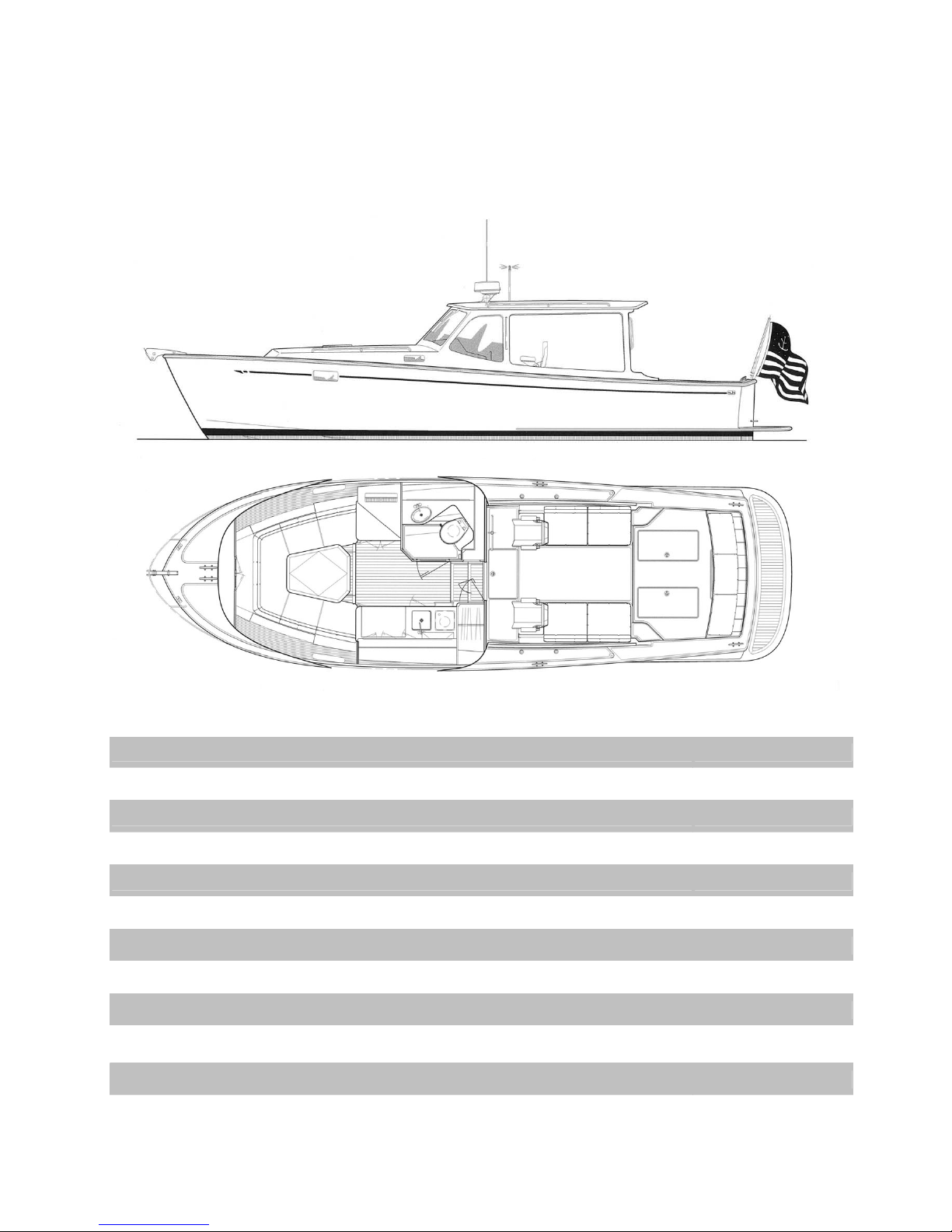
Length Overall 34 ft.
Length Waterline 31.3 ft.
Beam 11.0 ft.
Draft 2.4 ft.
Displacement (1/2 load) 10,600 lbs.
Fuel Tanks (combined) 144 gals.
Fresh Water Tank 55 gals.
Hot Water Tank 10 gals.
Holding Tank 20 gals.
Electrical Service
Height over Water (w/ radar) 9.5 ft.
Height over Road (w/ radar on trailer) Check, as will vary by trailer. Approx. 13.2 ft.
12VDC, 120VAC
(60Hz, Single Phase)
Note: This manual is published in accordance with ISO standard 10240:1995E Small Craft - O wner’s Manual

BOAT INFORMATION
BOAT
MODEL: 34z Downeast
HULL SERIAL # (HIN):
DESIGN PATENT: Patent No. US D475.338S (3Jun03)
DELIVERY DATE:
REGISTRATION #:
ENGINE
MAKE: Yanmar
MODEL: 6LY2A-STP 440HP
SERIAL #: ________
Mack Boring 24 Hour Service 1-800-622-5364____________________
TRANSMISSION
MAKE: ZF
MODEL: 280-A
SERIAL #:
RATIO: 2.0:1
PROPELLER
MAKE: ACME
BLADES: 4
DIA./PITCH: 22x27
OTHER: Right Hand
MJM YACHTS, LLC
CONTACT: Robert L. Johnstone
PHONE: 617-723-3629 MA
MOBILE: 401-862-4367
FAX: 617-723-3643
Email: bobj@mjmyachts.com
ADDRESS: 89 Pinckney St., Boston MA 02114
NAVAL ARCHITECT
NAME: Doug Zurn
FIRM: Zurn Yacht Design
PHONE: 781-639-0678
ADDRESS: 89 Front St., Marblehead, MA 01945
LICENSED BUILDER
NAME: Boston BoatWorks, LLC
CONTACT: Scott R. S. Smith
PHONE 617-561-9111
MOBILE 207-252-7190
FAX 617-561-9222
EMAIL scotts@bostonboatworks.com
ADDRESS 256 Marginal St., Boston MA 02128
DEALER
NAME:
PHONE:
ADDRESS:
- 3 - 34z

CE CERTIFICATION
CERTIFICATE NO. BBBW001 (30Sept03)
AUTHORITY: International Marine Certification Institute
ADDRESS: Rue Abbe Cuypers 3
B-1040 Bruxelles, Belgique
PHONE: +32-2-741-2418
WEBSITE: www.imci.org
CLASSIFICATION: CE Mark Design Category B Offshore Under 12m Small Craft (EC
Directive 94/25/EC) for craft designed for offshore voyages where
conditions up to and including wind force 8 (Beaufort Scale) and
significant wave heights up to and including 4 m may be experienced.
CAPACITY
PERSONS: Maximum 10, or 750 kg
PERSONS/GEAR: Maximum 1175 kg
-------------------------------------------------------------------------------------------------------------------------------------------RECEIPT BY OWNER
In compliance with ISO 10240:1995(E) the owner hereby certifies receipt
of this manual and has read and agrees to the terms of the Builder’s
Limited Warranty included herein.
Signature
Printed Name Date
Boat Name Hull #
Address
City, State, Zip
Tel.
Email
NOTE: PLEASE SIGN ONE OF THE TWO COPIES OF THIS PAGE AND RETURN IT IN THE
ATTACHED STAMPED ENVELOPE TO: MJM YACHTS at 89 Pinckney Street, Boston MA 02114.
Denotes an extreme intrinsic hazard exits which would result in high probability of
death or irreparable injury if proper precautions are not taken.
Denotes a hazard exists which can result in injury or death if proper preca utions
are not taken.
Denotes a reminder of saf ety practices or directs attention to unsafe practices
which could result in personal injury or damage to the craft or components.
- 4 - 34z

TABLE OF CONTENTS
CHAPTER 1 OPERATION
1.1 GENERAL
1.2 QUICK START GUIDE
1.3 OPERATING PROCEDURES
1.4 NAVIGATION
1.5 TOWING
1.6 HAULING OUT
CHAPTER 2 SAFETY EQUIPMENT
2.1 GENERAL
2.2 ENGINE
2.3 FIRE
2.4 FIRST AID
CHAPTER 3 PROPULSION SYSTEM
3.1 GENERAL
3.2 COOLING
3.3 LUBRICATION
3.4 ZINCS
3.5 AIR
3.6 PROPELLER
3.7 SHAFT SEALS
3.8 STARTING
3.9 STOPPING
3.10 RUNNING
3.11 THROTTLE CONTROL
3.12 INSTRUMENT GAUGES
CHAPTER 4 STEERING CONTROL
SYSTEM
4.1 GENERAL
4.2 STEERING
4.3 BOW-THRUSTER
4.4 TRIM TABS
4.5 AUTOPILOT OPERATION
4.6 WINDSHIELD WIPERS
4.7 SEASTAR HYDRAULIC STEERING
CHAPTER 5 FUEL SYSTEM
5.1 GENERAL
5.2 FILLING THE TANKS
5.3 CHECKING THE SYSTEM
5.4 FUEL CONSUMPTION & LOG
CHAPTER 6 ELECTRICAL SYSTEM
6.1 GENERAL
6.2 DC SYSTEM
6.3 AC SYSTEM
6.4 REVERSE POLARITY
6.5 ELECTROLYSIS & GALVANIC
CORROSION
6.6 BONDING
6.7 ELECTRICAL SAFETY
6.8 GENERATOR
6.9 INVERTER/CHARGER
CHAPTER 7 FRESHWATER SYSTEM
7.1 GENERAL
7.2 FILLING
7.3 USING & MAINTAINING
7.4 HOT WATER
7.5 WATER PURIFIER
CHAPTER 8 RAW WATER SYSTEM
8.1 GENERAL
8.2 ENGINE RAW WATER
8.3 ADDITIONAL RAW WATER USES
CHAPTER 9 GRAY WATER SYSTEM
9.1 GENERAL
9.2 GRAY WATER TANK
9.3 BILGE PUMPS
9.4 COMMON DRAINS
CHAPTER 10 EXTERIOR EQUIPMENT
10.1 GENERAL
10.2 ANCHOR WINDLASS
10.3 PILOTHOUSE CURTAINS
10.4 TRANSOM DOOR & SEAT
10.5 OUTBOARD STORAGE MOUNT
CHAPTER 11 INTERIOR EQUIPMENT
11.1 MARINE HEAD SYSTEM
11.2 REFRIGERATION
11.3 COOKTOP
11.4 MICROWAVE/OVEN
11.5 AIR-CONDITIONING (Optional)
11.6 HEATING SYSTEM (Optional)
11.7 STEREO & CD CHANGER
11.8 SIRIUS SATELLITE SYSTEM
11.9 TELEVISION
CHAPTER 12 ROUTINE MAINTENANCE
CHAPTER 13 SEASONAL MAINTENANCE
CHAPTER 14 FIGURES
14.1 EMERGENCY DIAGRAM
14.2 FUEL SYSTEM
14.3 DC SCHEMATIC (12 VOLT)
14.4 AC SCHEMATIC (120 VOLT)
14.5 FRESHWATER SYSTEM
14.6 RAW WATER SYSTEM
14.7 GRAY WATER SYSTEM
14.8 WASTE SYSTEM
14.9 STEERING SYSTEM
14.10 AIR-CONDITIONING SYSTEM
14.11 LIFT BUNKS & SLING DIAGRAMS
14.12 BRIDGE CLEARANCE
CHAPTER 15 LIMITED WARRANTY
CHAPTER 16 QUICK START
- 5 - 34z

CHAPTER 1 OPERATION
1.1 GENERAL
This manual has been compiled to help you operate your yacht with safety and pleasure. It
contains details of the yacht; the equipment supplied or fitted, its systems, and information on its
operation and maintenance. Please read it carefully, and familiarize yourself with the yacht
before using it.
If this is your first yacht, or you are changing to a type of yacht you are not familiar with, for your
own comfort and safety, please insure that you obtain handling and operating experience before
assuming command of the yacht. Your dealer or yacht club will be pleased to advise you of local
schools, or competent instructors.
PLEASE KEEP THIS MANUAL IN A SECURE PLACE, AND HAND IT OVER TO THE NEW
OWNER WHEN YOU SELL THE CRAFT.
This Owner’s Manual is not intended to be a course in boating safety, boat handling, navigation
or general boating skills. It is the responsibility of the user to independently gain these skills.
Instead, this manual will serve as a reference for matters specific to the 34z. Standard options
are included in the manual with which your particular yacht may or may not be fitted. Custom
options are addressed in an addendum.
1.2 QUICK START GUIDE (See CHAPTER 16)
A separate “Quick Start Guide” is included that briefly reviews the key items to check before
departure. Please review the topics in this manual before relying on the checklist – it is simply an
“at-a-glance” sheet to insure that you don’t overlook anything important.
1.3 OPERATING PROCEDURES – ENGINE INSPECTION
To access the propulsion system, the bridge-deck must be tilted up. The procedure is as follows:
Make sure personnel and equipment are clear of any moving parts before
operating.
- Turn ON house battery switch (located in the companionway step)
- Turn ON DC main disconnect breaker & engine hatch breaker at the DC panel
- Slide and secure helm seats all the way aft (so they don’t contact the wheel and navigation
station)
- Remove the backrest cushions
- Activate the lifts with the small black toggle switch over the starboard cockpit step
- When the bridge-deck nears the hardtop, STOP and attach the four-part safety tackle. (This
also serves to raise the hatch if you lose power.)
1.4 NAVIGATION
The builder installed navigation system option generally includes autopilot w/compass, depthsounder, chart-plotter, and radar. Modern marine electronics are a subject unto themselves and
you should refer to the manuals that came with the equipment you purchased. However, here are
a few points to consider:
If you are unfamiliar with navigation, educate yourself before using the boat. Electronic
equipment is NOT a substitute for navigation skills.
It is not recommended to rely solely on electronic charts- bring paper chart back-ups.
Depending on your chart-plotter, it may be necessary to power up the depth-sounder prior to
the chart-plotter.
- 6 - 34z

CHAPTER 1 OPERATION
It is prudent to check (or have checked) your compass alignment once the boat is in your
primary area of operation. See the Ritchie instructions for compensation.
Check that all equipment is functioning, even if you intend not to use it.
Radar functioning and properly aligned (Double-check when underway) See manual to
adjust, tune and operate.
Compass Heading & Calibration
There are 3 heading references for navigation on the 34z: (1) The compass on the dash, (2)
Autopilot fluxgate compass, and (3) GPS COG (Course Over Ground). All of these headings
should be within a degree or so of each other. If not, it is recommended that differences be
recorded on a deviation card after following the calibration method outlined below or employing
the services of a compass adjuster. Use COG as the primary reference at a time when you are
not influenced by wind/wave/tidal set. The fluxgate compass sensor is located on the forward
bulkhead of the hanging locker and is accessible by removing the bottom drawer under the
galley. Avoid storing steel or iron items such as tools in the bottom drawer, in the bottom of the
hanging locker or under the companionway treads.
Ship’s Compass Calibration Method
1) With the compass in its intended position, but not finally secured, select a course on your chart
using two identifiable marks, buoys or landmarks that are within ten degrees (10°) of the
north/south line. Try to select this course so that you can maneuver your boat "down range" of
the marks selected.
2) From a position down range of the North/South marks, and keeping the marks lined up, run
the boat visually along the northerly course selected. Turn the port/starboard compensator until
the compass reads correctly.
3) Reversing direction, run the boat southerly, again keeping the marks lined up. If the compass
is not correct at this time, there is an alignment error. To correct, rotate the compass itself to
remove one half of this error. Repeat Steps 1 and 2 and then recheck this Step 3.
4) Simply repeat the procedures of Steps 1, 2 and 3, except this time, using an east/west course
and the fore/aft compensator, although at this time any alignment error should have been
eliminated.
5) Upon completing the procedure, secure the compass in its final position.
Boat Speed Boats equipped with the Raymarine C120 plotter and the optional High Definition
Fishfinder fairing block with paddlewheel sensor (located in aft port cockpit locker) have the
capability of reading Boatspeed through the water and Water Temperature. SOG (Speed Over
Ground) is displayed by the chart-plotter. Eventually, you will learn to approximate boat speed
through the water by relating it to RPM on the tachometer. For instance, boat speed in knots is
about 70% of RPM in 100’s (1200 RPM = 8.3 kts) below 20 knots. Or at higher speeds
RPM/100 is approximately mph.
1.5 TOWING
Refer to the included NMMA publication “Sportfish, Cruisers, Yachts – Owner’s Manual” for
towing instructions.
1.6 HAULING OUT
A facility that is unfamiliar with the 34z may require information before hauling the boat with a
TraveLift or crane & straps. Refer to Figure 14.10 included in this manual. The keel (centerline of
the boat) and chines (edges) are solid fiberglass and should be used to position weight bearing
supports. You will note that the fore and aft lift points are located pretty much at either end of the
pilot house.
Point loading flat areas other than centerline and chine or setting the weight of
the hull on supports of insufficient area may result in damage to the hull.
- 7 - 34z

CHAPTER 2 SAFETY EQUIPMENT
2.1 GENERAL
Spend time reviewing where your safety equipment is and how it functions BEFORE you need it.
Remember, the best way to protect yourself and others from accidents is to eliminate potential
causes of accidents before they occur. Good seamanship and common sense go a long way in
this endeavor. [See Figure 14.1]
Here is a safety checklist derived in part from the USCG Vessel Check List. State Regulations
may vary:
PFD’s
A wearable USCG approved personal flotation device (life-jacket) must be provided for each
person aboard. On the 34z, these can be types I, II, III or V. Also, one type IV throwable PFD
must be immediately available for use.
Children under 13 years of age are required to wear a USCG life jacket that fits when underway
unless they are in an enclosed cabin or belowdecks.
Visual Distress Signals (VDS)
You must carry VDS’s aboard. If opera ting betwee n sunset and sunrise, they must be suitable for
night use and be within the age dates marked on the side of the flares. A minimum of 3 day/night
use combination pyrotechnic flares are required. For a list of USCG approved devices, see the
USCG recreational checklist.
Fire Extinguisher
In addition to the automatic fire suppression system fitted in the engine space, you are required to
carry at least one type B-1 extinguisher aboard, which is located outboard of the port helm seat.
This should be checked regularly.
EPIRB
Especially if operating offshore, an EPIRB (electronic position indicating radio beacon) is
recommended.
Ships Papers & Registration
You should carry the vessel’s registration papers and number plate
Pollution Regulation Plaques
5”x8” Oil Discharge Plaque and a 4”x9” Waste Discharge Placard sho uld be fixed were visible.
Charts & Light Lists
Charts, light lists and a USCG required copy of the Inland “Rules of the Road” Navigation Rules
Horn or Whistle
Recommended to signal intentions or signal position. For instance, when in a narrow channel or
the Intracoastal Waterway: To signal which side of another boat you will pass on, blow 1 blast if
you are passing to their starboard side and 2 blasts if passing on their port side..
Life Raft
If you plan to be coastal cruising out of sight of land, it is prudent to carry a Coastal Life Raft
which come in compact sizes that can be stored in one of the aft cockpit lockers.
Heaving Line
These floating lines are available and handy to have ready in case of emergency or to simply trail
behind the boat when swimming, .with the end attached to one of the stern cleats.
- 8 - 34z

CHAPTER 2 SAFETY EQUIPMENT
First Aid Kit
Not a place to scrimp. It is advisable to carry a good, comprehensive, and well-organized (by
injury) marine first-aid kit with manual. We recommend that it be stored in the head and that
everyone onboard be informed of its location. (Remember, you may be the one in need of it!)
2.2 ENGINE
Fuel shut-off valves are located on top of the fuel tanks and are accessible via spin-off deck
plates mounted by the cockpit steps [see fuel system section]. It is highly recommended that you
open these from time to time to insure that they have not become stuck. Make sure you know
how to shut off the fuel valves. (When the handle is perpendicular to the hose, the valve is
closed.) In case of a fuel fire, STOP any machinery and close the valves to cut the supply of fuel
to the fire. If you should ever see fuel in the bilges, turn off the valves, clean the bilges, and find
the source of the leak immediately.
2.3 FIRE
Fire aboard a boat is a serious matter, and fire safety begins with fire prevention. You can reduce
the risk of fire by following common sense guidelines:
Do not allow debris to collect in bilges or machinery spaces.
Understand your electrical system, allow only qualified marine electricians to work on it, and shut
down as many circuits as practical when leaving the boat. Do not leave appliances running while
unattended.
Have your fire suppression equipment inspected regularly and learn how to use it.
An automatic fire suppression system is installed on every boat in the engine space. It is heat
activated. Read the information that comes with the equipment. The system can also be manually
activated at the helm station. [See Helm Console Section] Because a diesel engine would
evacuate the suppression agent from the affected space, the system will shut down the engine
(and generator) when it discharges. If manually activating the system, the engine should be shut
down first. After the situation has stabilized, the shut-down feature can be over-ridden to restart
the engine. A loud warning alarm will sound when the system has been activated.
There is a hand-held fire extinguisher mounted outboard of the port helm seat. It is rated to fight
type A, B & C fires. Periodically check that this extinguisher is fully charged.
To extinguish a fire, the most effective method is to cut the source of fuel to the fire. In the case of
a diesel fuel fire, the fuel tank valves should be closed. In the case of an electrical fire, the main
battery switches or main disconnect breakers should be turned off. Fire needs oxygen to burn, so
if a fire should occur in an enclosed area, the best course of action may be to exit the area and
seal it from the outside by closing all means of air intake.
- 9 - 34z
CHAPTER 3 PROPULSION SYSTEM
y
3.1 GENERAL
The 34z is propelled by a diesel engine turning (via a transmission) a standard, four-blade
propeller. The single-lever control acts as a combination throttle and gear selector. Care should
be taken when shifting. Always allow the transmission to engage the new gear before throttling
up.
The engine should never be running when swimmers are near the boat.
Most of the propulsion system is accessed by tilting the bridge-deck (using the electri c lifts).
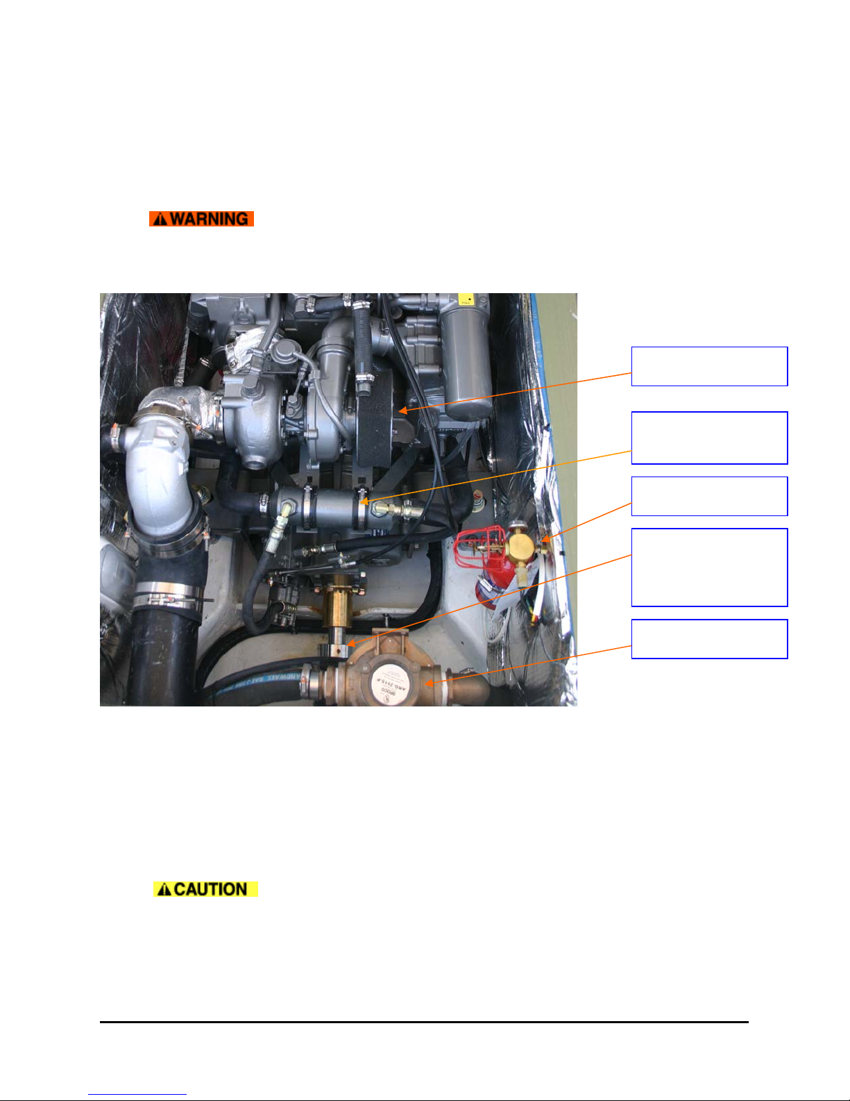
AIR FILTER
HEAT EXCHANGER
Transmission cooler
3.2 COOLING
Your engine passes seawater (raw water) through a heat exchanger where it cools the engine’s
coolant. This coolant is circulated through the engine and returns to the heat exchanger. For the
engine to keep cool, it must have an adequate supply of raw water and coolant. Before starting
the engine, the raw water intake seacock should be checked, the strainer visually inspected, and
the coolant level checked. Coolant should be visible in the plastic reservoir just forward of the
engine. (If it is not, remove the filler cap and check the level there.)
For details on what type of coolant to use, consult the engine operator’s manual or the
maintenance schedule included in this manual. It is recommended to check the raw water flow
after starting the engine by glancing at the exhaust outlets in the transom. Water should be
mixing with the exhaust gases and exiting the boat in noticeable surges.
Do not attempt to remove the coolant cap of a hot engine.
FIREBOY
SHAFT SEAL
Note: This photo does not
show the required Zinc
retainer installed forward of
the shin
PYI collar.
RAW WATER
- 10 - 34z
CHAPTER 3 PROPULSION SYSTEM
(
)
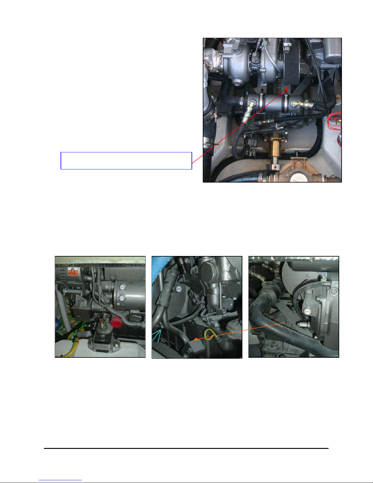
3.3 LUBRICATION
Both the engine and transmission use oil for
lubrication. The transmission will tend to use
less oil than the engine, but both should be
checked frequently. For the proper type of oils to
use (which may depend on the service area and
conditions) consult the maintenance schedule
below.
The engine oil may be checked on either side by
pulling the yellow dipstick on the port top of the
engine or the short dipstick shown in the middle
picture below (the shorter one provides more
accuracy). The transmission dipstick is red.
3.4 ZINCS
Transmission Dipstick under Bracket on ZF 280-A
2.0:1 Transmission
Looking Forward
In addition to drive shaft, bow-thruster and transom zincs, pay close attention to the engine zincs.
See pages 35 & 36 of the Yanmar Manual. The timing for replacing of the 5 anticorrosive engine
zincs varies depending on the characteristics of the seawater, the amount of electrical current in
marinas, or could indicate (if excessive wear is noted) an electrical short on the boat, etc. Inspect
these periodically at the time of oil changes and remove the corroded area on the surface,
replacing them when they’ve deteriorated to less than 50% of original size. Otherwise corrosion
of the seawater cooling system will occur and water leakage or parts breakage will result. Be
sure to close the Kingston (raw seawater) cock before removing the plug to replace a zinc.
Freshwater Cooler (2 zincs) Engine Lube Oil Cooler (2 zincs) Intercooler (1 zinc)
(Port Forward Corner) & 2
3.5 AIR
Diesel engines use a large quantity of air for combustion. The engine of the 34z gets this air thru
grills under the cockpit coaming, both port and starboard. It is important to keep these intakes
clear and free of foreign matter. Before entering the engine, air passes thru a foam air filter which
should be checked at intervals per the maintenance schedule.
- 11 - 34z
nd
Oil Dipstick (Starboard Forward) (Starboard Side Aft)

CHAPTER 3 PROPULSION SYSTEM
3.6 PROPELLER
The 34z uses a right-hand or left-hand propeller, depending on the customer’s preference. The
primary difference is in boat handling characteristics at low speed, especially in reverse. A righthand prop will tend to pull the stern to port when backing. The same transmission is used for
either prop and is factory set for the orientation of your propeller. This is easily changed if you
should ever decide to switch propeller orientation.
3.7 SHAFT SEALS
The prop shaft exits the boat just aft of the transmission. The seal that keeps water from entering
the boat is drip-less. It is not uncommon, especially while breaking-in the seal, to see some
temporary dripping. After this period though, the seal should remain virtually dry. The tube
attached to the seal provides a raw water supply for cooling.
Be sure shaft seal collar is secured to shaft with doughnut shaped zinc in
front of it. If the collar slides forward there is a risk of significant water ingress.
3.8 STARTING
Before starting the engine, make sure that the raw water
intake seacock is open, that the strainer is clean, the
engine has sufficient oil and coolant and that there are
no restrictions to the air intake grills. Check that the fuel selector switch is in either the PO RT,
STARBOARD, or BOTH position. Also, the throttle must be in the neutral position. Insure that no
one is in the water near the boat and that all machinery space hatches are closed. Check the
state of the batteries to insure that there has not been an unexpected drain. Make sure the
battery selector switches for the engine start bank and the house battery bank are both ON. Turn
the key to ON and note the fuel level gauges. Then, turn the key to the START position (all the
way to the right) and hold it there until the engine runs. If the starter is audibly working, but the
engine fails to fire, do not hold the key in the START position for more than 10 seconds as
damage to the starter may result and the battery may become discharged. Consult the operator’s
manual for troubleshooting recommendations.
Note: the transmission has a neutral safety switch that prevents the engine from starting in any
gear but neutral. If the throttle control appears to be in neutral but the engine will not crank, one
possible reason is that the neutral safety switch is calibrated incorrectly. This should be checked
after it is verified that the engine start battery switch is ON and that it has proper voltage. Also
check the engine manual for troubleshooting procedures.
IGNITION PANEL
WINDLASS CONTROL & BREAKER
12v DC OUTLET
ENGINE FIRE SUPPRESSION
BOW THRUSTER INTERRUPT
- 12 - 34z

CHAPTER 3 PROPULSION SYSTEM
3.9 STOPPING
Before shutting down the engine, allow it to cool down by idling in neutral for 5 minutes. Then,
press and hold the red button on the engine panel until the engine comes to a complete stop.
Make sure to turn the key to the OFF position after the engine stops so that the engine hour
meter stops. Note that if the key is switched OFF before the red button is pushed, the button will
not shut-down the engine.
3.10 RUNNING
The Yanmar 6LY2A is rated at a maximum RPM of 3400. Running the engine at full throttle is not
recommended for extended periods of time. Yanmar claims that the engine can be run “all day” at
200 RPM under the max RPM. At 2800 RPM, you should be cruising at 24-26 knots, depending
on load, wind, etc. It’s whatever seems comfortable considering conditions. While running, pay
attention to the instrument gauges on the dash console. A significant change in temperature, oil
pressure, or voltage should be investigated immediately, before the engine is damaged.
3.11 THROTTLE CONTROL
The single-lever control to the starboard side of the console governs both the throttle and shifting
functions. It is important to allow the transmission to engage into forward (or reverse) before
throttling up. The boat utilizes a powerful propeller with a large rudder immediately behind. It is
uncommon in docking situations to ever need more than a short, momentary forward or reverse
thrust.
Crabbing Sideways: Since there is more directional response with the helm hard over in forward
than in reverse, due to the prop wash bouncing off the rudder, it is possible in combination with
the bow-thruster to crab the boat sideways for an eggshell landing. For example, to move the
boat sideways to starboard from a dead stop: Turn the wheel fully to port. Give the throttle a
short burst FWD for 1-2 seconds. The stern is pushed to starboard. To keep the boat parallel
with the dock, or another boat you are rafting up to, tap the bowthruster to STBD. If the boat
starts sliding forward, give it a touch of reverse to hold station. Repeat process above several
times. This is a skill that is best practiced in open water before attempting docking maneuvers.
To increase RPMs in neutral, you must have the lever in the neutral position and then pull the
handle outboard, then advance it forward while it is out of gear.
3.12 INSTRUMENT GAUGES
The engine instrument gauges provide you data on the status of the engine. They are powered
via the ignition switch and will not display data when the key is in the OFF position. The
tachometer allows you to monitor the RPM of the engine. It is common and efficient to cruise at
85% of the rated maximum RPM, or 2800 RPM. For acceptable ranges of temperatures and oil
pressures shown in other gauges, consult the engine’s operator’s manual.
- 13 - 34z
CHAPTER 4 STEERING CONTROL SYSTEM
A
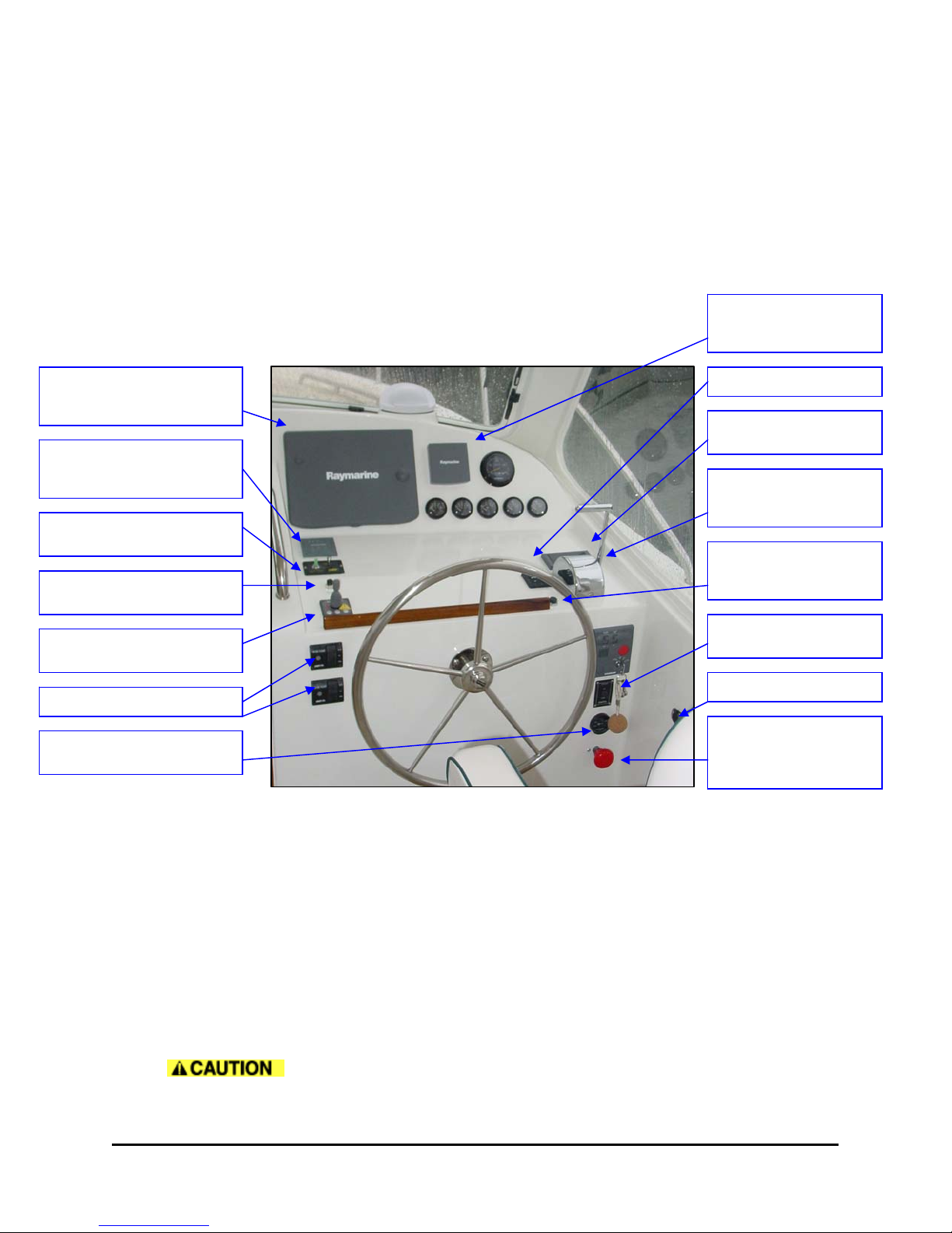
4.1 GENERAL
The helm control console is where most of the operation controls of the boat are located. Become
familiar with these before you need to use them. You don’t want to be looking for your glasses
and a flashlight while trying to turn on the bow-thruster at night! In addition, make sure that when
you are using the boat, even if you are not using a specific piece of equipment, that the circuit
breakers are on for any equipment you might need. Again, you don’t want to be searching for a
breaker when you need something in a hurry.
Some of the instruments on the console are powered by the ignition switch and will not function
without the key in the ON position, much like a car.
GPS Plotter/Radar &
Fathometer
Windshield Wiper and
Washer Controls
Searchlight Control
Horn Button
Bow Thruster Joystick
uto Bilge Pump Controls
Fire Suppressant System
4.2 STEERING
Steering of the 34z is a manual hydraulic system. The helm that you control at the console turns a
pump, which drives hydraulic steering fluid to the cylinder, mounted aft by the rudderpost. The
cylinder drives a piston that is attached to the tiller arm, which is keyed to the rudderpost. [see
steering system] Unlike an outboard engine, the thrust of the propeller cannot be directed from
side to side. Turning forces are created by passing the propwash over the rudder. Low-speed
maneuverability feels different than an outboard boat, especially in reverse. Refer to the steering
equipment manual for instructions for purging and troubleshooting the hydraulic steering system.
4.3 BOW-THRUSTER (Optional)
If fitted, a bow-thruster can be used to greatly increase the maneuverability of the boat at slow
speeds in tight quarters around docks and slips.
their prior knowledge.
Autopilot & Rudder
Angle Indicator
Trim Tab Switches
Engine Warning
Single Lever Throttle
and Gear Shift
Hydraulic Fluid Fill
Cap
Windlass Control
12v Cellphone Outlet
Bow Thruster
Emergency Push to
Disconnect
Passengers on the foredeck are at risk if the thruster is engaged without
- 14 - 34z

CHAPTER 4 STEERING CONTROL SYSTEM
Consult the user’s manual for specifics about your thruster. In general, thrusters are best used in
short bursts. Prolonged use may damage the motor, or at least trip the breaker. When not in a
situation where the thruster may be necessary, leave it turned OFF to avoid damage. Consider
the fact that your thruster gets DC power from the engine start battery, which is charged by the
engine’s alternator. If the engine is not running, or running at idle, the thruster can consume more
energy than the alternator can provide. It is possible to discharge the battery by over-use of the
thruster.
Turn on the bow-thruster by holding down the two left buttons (or turning the switch to ON with
some models) until the activation light appears. If the light does not appear, check to see that the
large red knob for the bow-thruster circuit breaker (below ignition panel) is pulled out.
When operating the bow-thruster, allow the propeller to come to complete
stop before reversing direction. Failure to do so may result in damage to the shear pin.
The bow-thruster zincs should be checked periodically and replaced if
significantly worn.
4.4 TRIM TABS
While trim tabs are not necessary on the 34z, which runs at 3-5 degree angles, they do come in
handy to fine-tune the trim and running angle of the 34z. The trim tab breaker on the DC panel
must be ON for the unit to work. The trim tabs are wired intuitively, so by pushing down the
starboard tab, the bow leans down to starboard. (Actually, the port tab is going down to lift the
port aft corner of the boat).
Trim tabs aren’t necessary at low or high speeds . They are useful in lowering the bow for better
visibility or for slicing through a small chop at moderate speeds. At higher speeds when the boat
naturally runs flatter and when running downsea into the back of waves, it’s advisable to raise the
trim tabs for dry running and control, allowing the bow to lift.
Lenco trim tabs are powered by DC electricity on Hulls #5 and higher. On hulls #1 through #4
Bennett trim tabs operate by supplying DC electric power to a hydraulic pumpset, located aft by
the steering quadrant under the aft cockpit hatch. The level of hydraulic fluid should be
periodically checked in the clear reservoir.
4.5 AUTOPILOT OPERATION (Optional)
The Autopilot/Depth breaker (on the DC panel) must be ON for the autopilot to function. Check
the autopilot display and note the rudder angle indicator which helps in maneuvering the boat.
When the compass heading is displayed on the autopilot it is operational and can be activated by
pushing AUTO. The boat will then maintain the displayed heading. Push +1 or -1 for one degree
course corrections or +10 or –10 for ten degree increments.
The autopilot system is part of the hydraulic steering system. DO NOT
turn the wheel when the autopilot system is ON. Push STANDBY to switch back to manual
steering.
4.6 WINDSHIELD WIPERS
The 34z is fitted with two windshield wipers. For specific instructions, refer to the user manual.
The wash feature is connected to your boat’s freshwater system and requires that the system be
pressurized (i.e. that the freshwater pump is ON). If the wipers are to be used in sub-freezing
temperatures, a separate system must be installed which utilizes anti-freeze.
- 15 - 34z
CHAPTER 4 STEERING CONTROL SYSTEM
4.7 SEASTAR HYDRAULIC STEERING
With a hydraulic system that allows both the wheel and the autopilot to move the rudder, there are some
unique requirements. For more information log onto www.seastar.com
department at info@teleflex.bc.ca
Gloucester MA.
or contact the nearest distributor or Rose Marine at 978-283-0293 in
or email the technical service
Oil Level and System Check
Even though the Seastar system is supposed to be selfbleeding to purge any air, check the level of hydraulic fluid
weekly, by unscrewing the filler cap on the helm console
above the wheel. If you don’t see fluid, add more Seastar
hydraulic fluid.
There is a central hydraulic reservoir & helm pump mounted
just under this fill cap mounted on top of the piloting console
forward of the wheel. It supplies the entire system.
With the filler hose still screwed into the filler cap, CHECK
the steering system for proper connections of hose, tube and
fittings, possible leaks, and air removal. To do so, turn
steering wheel and pressurize very hard to port. Apply
enough force to the wheel to exceed pressure relief valve pressure. You will not harm the helm or the
system. While pressure is maintained on the steering wheel, check all port (left) fittings and line
connections. Repeat procedure by turning wheel to starboard. Watch the oil level in the helm pump when
pressurizing the steering wheel in either hard over positions. If there is no obvious drop in oil level, air has
been removed. If there is an obvious drop in oil level, you are compressing air and further filling and
purging is required. Repeat Steps 1 thru 5. If no leaks are obvious, your steering system is ready for use.
If leaks are found, correct before using. Failure to correct a leak can lower oil level in system and result in
loss of steering.
Suggested 34z Procedure
1. Screw the plastic filler hose (found in a galley drawer) into the filler cap’s socket before
connecting it to the Seastar plastic bottle.
2. Loop the hose over 180 degrees that’s now sticking out of the filler gap, so that the bottle can
then be turned under the cap to screw it on.
3. While keeping the bottle nearly upright, squeeze about 4 inches of fluid into the tube and turn the
wheel full starboard then full port quickly, to release any air bubbles and to refill to within ¼” of
top.
4. If the steering feels jerky or strange, there maybe air trapped in the cylinder attached to the
rudder post. (Read the “Fill & Purge” instructions below) but this can usually be solved by quickly
bleeding the valves on top of the cylinder, using the discharge hose that connects the two
bleeding valves to empty oil into a container.
5. Have a helper move the wheel with a couple of short jerky motions to be sure all air is bled. Then
go back to step one to refill the reservoir. The Raymarine Autopilot has a rudder angle indicator
that is helpful in knowing whether the rudder is doing what it should.
6. If you have had to add a significant amount of fluid, be sure to (a) check for leakage and a tight fit
at all hose connections and (b) check once again for fluid level after operating th e autopilot for a
short period of time to be sure that no air has been trapped in that part of the system.
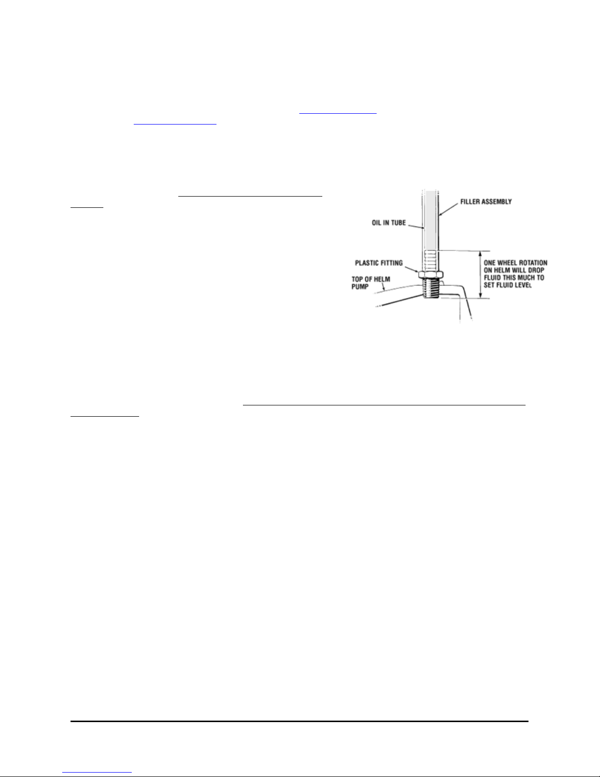
Oil Level Set
Proper oil level set can be obtained by opening bleeder and turning steering wheel until fluid level
reaches top of plastic filler fitting and then turning wheel one more full turn.
- 16 - 34z
CHAPTER 4 STEERING CONTROL SYSTEM
As indicated in applicable diagram in step 5 below.
For unbalanced cylinders the oil level in the helm must be set with the cylinder rod
fully retracted. Failing to observe this caution will result in an oil spill at the helm.
Turning the wheel port (left) will retract the cylinder rod.
Filling & Purging the SeaStar System
This procedure requires two people. One person may not be able to remove all the air from the
system which will result in spongy, unresponsive steering.
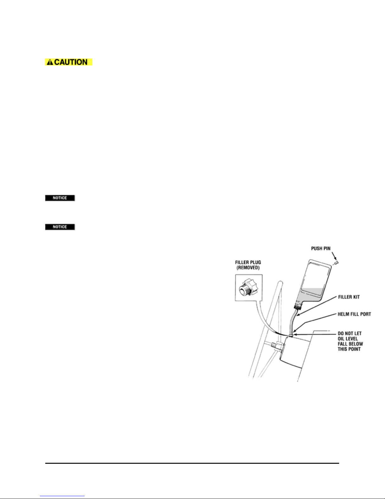
During the entire filling procedure, oil must be visible in the filler tube. Do not allow the oil level to
disappear into the helm pump, as this may introduce air into the system and increase your filling time
Hydraulic Fluid/Oil Requirements
2 bottles (2 quarts or liters) for single station and single cylinder systems.
1 additional bottle for each additional helm, cylinder, or auto pilot.
These instructions will result in hydraulic oil flushed in and out of the system. Oil can be reused
if filtered through a fine mesh screen such as used for gasoline. If unable to filter oil, an additional bottle
of oil is required.
tee fitting, open bleeder by unscrewing bleed nipple nut two turns.
If cylinder is fitted with bleed screws, open bleeder by
removing bleed screw completely. Loosening bleed screw
only, will not cause sufficient oil flow to purge system.
Recommended oils for your steering system are:
• SeaStar Hydraulic Fluid, part# HA5430
• Texaco HO15
• Shell Aero 4
• Esso Univis N15
• Chevron Aviation Fluid A
"Bleeder" may refer to cylinders fitted with bleed tee fittings or bleed screws. If fitted with bleed
• Mobil Aero HFA
• Fluids meeting Mil H5606C specifications.
• Automatic transmission fluid Dexron II may be used in an
emergency.
• Never use brake fluid. Any non-approved fluid may cause irreparable damage, loss of steering, and
cancellation of warranty.
In cases of extreme emergency any non-toxic, non-flammable fluid may provide temporary
steering.
- 17 - 34z
 Loading...