

mjm yachts 36z Downeast Owner's Manual

Note: This manual is published in accordance with ISO standard 10240:1995E Small Craft - Owner’s Manual
1
89 Pinckney Street, Boston MA 02114
Tel 617-723-3629 Fax 617-723-3629
March 2011
Dear 36z Owner:
Congratulations on becoming Captain and Owner of the world’s best built and most fuel efficient yacht of its size.
The enclosed copy of the 36z Owner’s Manual should further contribute to your enjoyment and proficiency afloat.
This manual was created jointly with Zurn Yacht Design, Boston BoatWorks and MJM Yachts. Our experience
with the 120 boats (40z’s 34z’s and 29z’s included) built to date has been incorporated to make this manual as
useful and relevant as possible. Keep in mind there maybe some variances such as location of the breakers on the
panel. And, from time-to-time we will change specifications to keep pace with changes made to improve the boat.
When addressing a problem with a specific piece of equipment, this 36z Owner’s Manual is to be regarded only as a
preliminary source of information. The equipment manufacturer’s own manual with trouble-shooting procedures,
etc. is the primary source and authority.
An ISO CE Mark “Owner’s Manual” accompanies, and forms part of, this MJM produced 36z Owner Manual. This
booklet has many universal handling and operating tips worth reviewing.
This Owner’s Manual is designed to be a living document, not only for builder updates but for your own use and
record. Each boat is provided with a copy of the current Manual organized in a STAPLES “Mini-Ring” type binder
that allows you to add pages as needed.
One of the great advantages of purchasing a series-built or semi-custom design is that owners have the benefit of
learning from one another. So, with your continued input and comments we can keep adding useful information and
helpful hints to this manual.
Part of the ISO CE Mark Certification Program is confirmation by the owner that the manual has been received.
Please sign the extra page No. 3 included in the Manual as a receipt and return it in the stamped envelope provided.
Best wishes for fair winds and sunny skies. On behalf of the builder and designer, we are most appreciative, and I
am particularly honored, that you have chosen the 36z.
Robert L. Johnstone
Chief Operating Member
Note: This manual is published in accordance with ISO standard 10240:1995E Small Craft - Owner’s Manual
2
Length Overall (Including Swim Platform and Bow Roller)
39.3 ft.
Length on Deck
36.0 ft.
Length Waterline
33.3 ft.
Beam
11.0 ft.
Hull Draft/Max Draft with Drives Down
1.5 ft/2.5”
Displacement (1/2 load)
13,100 lbs.
Fuel Tanks (combined)
200 gals.
Fresh Water Tank
100 gals.
Hot Water Tank
13 gals.
Holding Tank
25 gals.
Height over Water (w/ radar mounted directly on hard top)
Approx 9.0’ ft.
Height over Road (w/ radar on trailer) Check, as will vary by trailer.
Approx. 12.5 ft.
36z

2
Subject: BOAT INFORMATION
BOAT
MODEL: 36z Downeast
HULL SERIAL # (HIN): EOU36z04K011
DESIGN PATENT: Patent No. US D475.338S (3Jun03)
DELIVERY DATE: January 4, 2011_______
REGISTRATION #:
ENGINES
MAKE: Volvo-Penta
MODEL: D3- 220A-3 DPS
SERIAL #: 2003018715 and 716
Volvo 24 Hour Service 877-747-3682 or Joel Rumelhart 207-632-6868
DRIVES
MAKE: Volvo-Penta # 3869465
MODEL: DPS-A-OXI
Serial#: A152600 and 601 SKX TSK A149444 & 447
RATIO: 1:78:1
PROPELLERS
MAKE: Volvo#3851494
BLADES: Duo Props – 4 Blade
DIA./PITCH: F4 SS DuoProp ______
OTHER:
MJM YACHTS, LLC
CONTACT: Robert L. Johnstone
PHONE: 617-723-3629 MA
MOBILE: 401-862-4367
FAX: 617-723-3643
Email: bobj@mjmyachts.com
ADDRESS: 89 Pinckney St., Boston MA 02114
NAVAL ARCHITECT
NAME: Doug Zurn
FIRM: Zurn Yacht Design
PHONE: 781-639-0678
ADDRESS: 89 Front St., Marblehead, MA 01945
LICENSED BUILDER
NAME: Boston BoatWorks, LLC
CONTACT: Scott R. S. Smith
PHONE 617-561-9111
MOBILE 207-252-7190
FAX 617-561-9222
EMAIL scotts@bostonboatworks.com
ADDRESS 256 Marginal St., Boston MA 02128
DEALER
PHONE:
ADDRESS:
CE CERTIFICATION
CERTIFICATE NO. BBBW003 (pending)

3
AUTHORITY: International Marine Certification Institute
ADDRESS: Rue Abbe Cuypers 3
B-1040 Bruxelles, Belgique
PHONE: +32-2-741-2418
WEBSITE: www.imci.org
CLASSIFICATION: ISO CE Mark Design Category A Ocean (EC Directive 94/25/EC) for
craft designed for offshore voyages (1) where the vessel is correctly
handled in the sense of good seamanship and operated at a speed
appropriate to the prevailing sea state and (2) with significant wave
heights above 4 m (calculations are based on 7 m) and wind speeds in
excess of Beautort Force 8, but excluding abnormal conditions, e.g.
hurricanes.
CAPACITY
PERSONS: Maximum 12 Persons
PERSONS/GEAR: Maximum Load
--------------------------------------------------------------------------------------------------------------------------------------------
RECEIPT BY OWNER In compliance with ISO 10240:1995(E) the owner hereby certifies receipt
of this manual and has read and agrees to the terms of the Builder’s Limited Warranty included herein.
Signature
Printed Name Date
Boat Name Hull #
Address
City, State, Zip
Tel.
Email
NOTE: PLEASE SIGN ONE OF THE TWO COPIES OF THIS PAGE AND RETURN IT IN THE
ATTACHED STAMPED ENVELOPE TO: MJM YACHTS at 89 Pinckney Street, Boston MA 02114.
Denotes an extreme intrinsic hazard exits which would result in high probability of
death or irreparable injury if proper precautions are not taken.
Denotes a hazard exists which can result in injury or death if proper precautions
are not taken.
Denotes a reminder of safety practices or directs attention to unsafe practices
which could result in personal injury or damage to the craft or components.

TABLE OF CONTENTS
4
CHAPTER 1 OPERATION
1.0 GENERAL
1.1 QUICK START GUIDE
1.2 OPERATING PROCEDURES
1.3 NAVIGATION
1.4 TOWING
1.5 HAULING OUT
CHAPTER 2 SAFETY EQUIPMENT
2.0 GENERAL
2.1 FUEL SHUT-OFFS
2.2 FIRE
CHAPTER 3 PROPULSION SYSTEM
INTRO – TOP 10 REASONS of ENGINE FAILURE
3.0 GENERAL
3.1 NEW ENGINE BREAK IN
3.2 LUBRICATION
3.3 ZINCS
3.4 AIR INTAKES
3.5 EVC CONTROL PANEL
3.6 EVC DISPLAY
3.7 THROTTLE/SHIFT
3.8 STARTING
3.9 ALARMS
3.10 STOPPING
3.11 OPERATION
CHAPTER 4 STEERING SYSTEM
4.0 JOYSTICK DOCKING
4.1 HELM STATION
4.2 CONSOLE SWITCHES
4.3 POWER TRIM CONTROL
4.4 TRIM MODE OPTIONS
4.5 BOW THRUSTER (IF INSTALLED)
4.6 TRIM TABS
4.8 AUTOPILOT
4.9 WINDSHIELD WIPERS
CHAPTER 5 FUEL SYSTEM
5.0 GENERAL
5.1 FUEL SHUT OFFS
5.2 FILLING THE TANKS
5.3 RACOR FILTERS
5.4 FUEL CONSUMPTION & LOG
CHAPTER 6 ELECTRICAL SYSTEM
6.0 GENERAL
6.1 12 VOLT DC SYSTEM
6.2 120 VOLT 60 CYCLE AC SYSTEM
6.3 INVERTER/CHARGER
6.4 SHORE POWER
6.5 AC GENERATOR
6.6 REVERSE POLARITY
6.7 ELECTROLYSIS & CORROSION
6.8 BONDING
6.9 ELECTRICAL SAFETY
6.10 BREAKER & FUSE LOCATIONS
6.11 RAYMARINE FUSE LOCATIONS
6.12 INLINE & ANL FUSE LOCATIONS
CHAPTER 7 FRESHWATER SYSTEM
7.0 GENERAL
7.1 FILLING
7.2 USING & MAINTAINING
7.3 DOCK INLET
7.4 HOT WATER
7.5 WATER PURIFIER
CHAPTER 8 RAW WATER SYSTEM
8.0 GENERAL
8.1 ENGINE RAW WATER
8.2 ADDITIONAL RAW WATER USES
CHAPTER 9 SANITATION SYSTEM
9.1 VACUFLUSH
CHAPTER 10 GRAY WATER SYSTEM
10.1 GENERAL
10.2 GRAY WATER TANK
10.3 BILGE PUMPS
10.4 HIGH WATER ALARM
10.5 COMMON DRAINS
CHAPTER 11 OPTIONAL EQUIPMENT
11.0 OPEN
11.1 GENERAL
11.2 ANCHOR WINDLASS
11.3 PILOTHOUSE CURTAINS
11.4 PRIVACY/SUNSCREEN CURTAINS
11.5 REFRIGERATION
11.6 COOKTOP
11.7 MICROWAVE/OVEN
11.8 AIR-CONDITIONING
11.9 DIESEL HEATER
11.10 CLARION STEREO
11.11 SIRIUS SATELLITE SYSTEM
11.12 SAMSUNG TELEVISION
11.13 FLIR NIGHT VISION
CHAPTER 12 ROUTINE MAINTENANCE
VOLVO SCHEDULE
ENGINE DIAGRAMS
CHAPTER 13 SEASONAL MAINTENANCE
CHAPTER 14 FIGURES
14.0 SYSTEMS
14.14 TRUCKING CHECKLIST
CHAPTER 15 LIMITED WARRANTY
CHAPTER 16 QUICK START

CHAPTER 1 OPERATION
5
1.1 GENERAL
This manual has been compiled to help you operate your yacht with safety and pleasure. It
contains details of the yacht; the equipment supplied or fitted, its systems, and information on its
operation and maintenance. Please read it carefully, and familiarize yourself with the yacht
before using it.
If this is your first yacht, or you are changing to a type of yacht you are not familiar with, for your
own comfort and safety, please insure that you obtain handling and operating experience before
assuming command of the yacht. Your dealer or yacht club will be pleased to advise you of local
schools, or competent instructors.
PLEASE KEEP THIS MANUAL IN A SECURE PLACE ON THE BOAT, AND HAND IT OVER TO
THE NEW OWNER IF YOU EVER SELL THE CRAFT.
This Owner’s Manual is not intended to be a course in boating safety, boat handling, navigation
or general boating skills. It is the responsibility of the user to independently gain these skills.
Instead, this manual will serve as a reference for matters specific to the 36z. Standard options
are included in the manual with which your particular yacht may or may not be fitted. Custom
options may be addressed in an addendum.
1.2 QUICK START GUIDE (See CHAPTER 16)
A separate “Quick Start Guide” is included that briefly reviews the key items to check before
departure. Please review the topics in this manual before relying on the checklist – it is simply an
“at-a-glance” sheet to insure that you don’t overlook anything important.
1.3 OPERATING PROCEDURES – ENGINE INSPECTION
To access the propulsion system, the cockpit engine hatch must be raised. The procedure is as
follows:
Make sure personnel and equipment are clear of any moving parts before
operating.
- Turn ON house battery switch (located in top right of DC electrical panel)
- Turn ON DC main disconnect breaker & engine hatch breaker at the DC panel
- Activate the lift with the small black rubber toggle switch located in the starboard cockpit seat
locker.
1.4 NAVIGATION
The optional builder installed navigation system includes autopilot w/compass, depth-sounder,
chart-plotter, and radar. Modern marine electronics are a subject unto themselves and you should
refer to the manuals that came with the equipment you purchased. However, here are a few
points to consider:
! If you are unfamiliar with navigation, educate yourself before using the boat. Electronic
equipment is NOT a substitute for dead-reckoning navigation skills.
! It is not recommended to rely solely on electronic charts- bring paper chart back-ups.
! It is prudent to check (or have checked) your compass alignment once the boat is in your
primary area of operation. See the Ritchie instructions for compensation.
! Check that all equipment is functioning, even if you intend not to use it.
! Radar and its overlay projection on the plotter should be properly aligned (Double-check
when underway) See manual to adjust, tune and operate.

CHAPTER 1 OPERATION
6
Compass Heading & Calibration
There are 3 heading references for navigation on the 36z: (1) The compass on the dash, (2)
Autopilot digital compass, and (3) GPS COG (Course Over Ground). All of these headings should
be within a degree or so of each other when underway. If not, it is recommended that differences
be recorded on a deviation card after following the calibration method outlined below or
employing the services of a compass adjuster. Use COG as the primary reference at a time
when you are not influenced by wind/wave/tidal set. The digital compass sensor is located on a
stringer outboard to port under the cabin sole. It is accessible by opening the cabin sole hatch
and looking aft and to port. Avoid storing steel or iron items such as tools
next to it.
Ritchie Ship’s Compass Calibration Method
1) With the compass in its intended position, but not finally secured, select a course on your chart
using two identifiable marks, buoys or landmarks that are within ten degrees (10°) of the
north/south line. Try to select this course so that you can maneuver your boat "down range" of
the marks selected.
2) From a position down range of the North/South marks, and keeping the marks lined up, run
the boat visually along the northerly course selected. Turn the port/starboard compensator until
the compass reads correctly.
3) Reversing direction, run the boat southerly, again keeping the marks lined up. If the compass
is not correct at this time, there is an alignment error. To correct, rotate the compass itself to
remove one half of this error. Repeat Steps 1 and 2 and then recheck this Step 3.
4) Simply repeat the procedures of Steps 1, 2 and 3, except this time, using an east/west course
and the fore/aft compensator, although at this time any alignment error should have been
eliminated.
5) Upon completing the procedure, secure the compass in its final position.
Boat Speed Rather than a paddle-wheel or sonic device, the Raymarine C120 plotter is used
to generate SOG (Speed Over Ground) that is displayed by the chart-plotter and may also be
shown in larger digits on the Autopilot display. Eventually, you will learn to approximate boat
speed through the water by relating it to RPM on the tachometer.
1.5 TOWING
Refer to the included ISO Owner’s Manual or to a book on seamanship and boat handling for
towing guidelines.
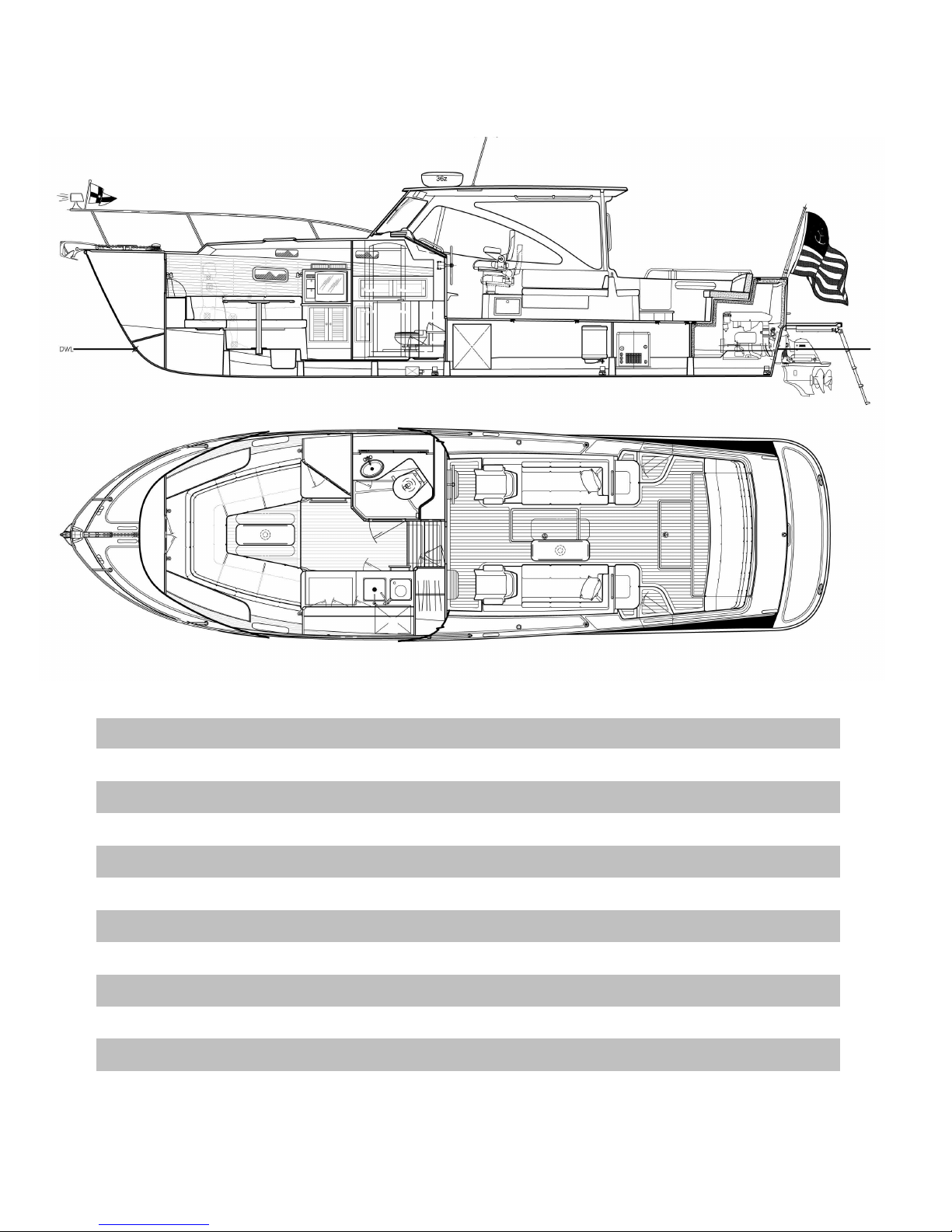
1.6 HAULING OUT
A facility that is unfamiliar with the 36z may require information before hauling the boat with a
Travel-Lift or crane & straps. Refer to the illustration included at the back of this manual. The
keel (centerline of the boat) and chines (edges) should be used to position weight bearing
supports. You will note that the fore and aft lift points are located approximately at either end of
the pilot house... e.g. abeam of the windshield and the aft end of the hard top.
Point loading flat areas other than centerline and chine or setting the weight of
the hull on supports of insufficient area may result in damage to the hull.

CHAPTER 2 SAFETY EQUIPMENT
2.1 GENERAL
Spend time reviewing where your safety equipment is and how it functions BEFORE you need it.
Remember, the best way to protect yourself and others from accidents is to eliminate potential
causes of accidents before they occur. Good seamanship and common sense go a long way in
this endeavor. [See Figure 14.1]
Here is a safety checklist derived in part from the USCG Vessel Check List. State Regulations
may vary:
PFD’s
A wearable USCG approved personal flotation device (life-jacket) must be provided for each
person aboard. On the 36z, these can be types I, II, III or V. Also, one type IV throwable PFD
must be immediately available for use. Children under 13 years of age are required to wear a
USCG life jacket that fits when underway unless they are in an enclosed cabin or belowdecks.
Visual Distress Signals (VDS)
You must carry VDS’s aboard. If operating between sunset and sunrise, they must be suitable for
night use and be within the age dates marked on the side of the flares. A minimum of 3 day/night
use combination pyrotechnic flares are required. For a list of USCG approved devices, see the
USCG recreational checklist.
Fire Extinguisher
In addition to the automatic fire suppression system fitted in the engine space, you are required to
carry at least one type B-1 extinguisher aboard. This should be checked regularly.
EPIRB
If operating offshore, an EPIRB (electronic position indicating radio beacon) is recommended.
Ships Papers & Registration
You should carry the vessel’s registration papers and number plate.
Pollution Regulation Plaques
5”x8” Oil Discharge Plaque and a 4”x9” Waste Discharge Placard should be fixed were visible.
Charts & Light Lists
Charts, light lists and a USCG required copy of the Inland “Rules of the Road” Navigation Rules
Horn or Whistle
Recommended to signal intentions or signal position. For instance, when in a narrow channel or
the Intracoastal Waterway: To signal which side of another boat you will pass on, blow 1 blast if
you are passing to their starboard side and 2 blasts if passing on their port side.
Life Raft
If you plan to be coastal cruising out of sight of land, it is prudent to carry a Coastal Life Raft
which come in compact sizes that can be stored in one of the aft cockpit lockers.
Heaving Line
These floating lines are available and handy to have ready in case of emergency or to simply trail
behind the boat when swimming, .with the end attached to one of the stern cleats.
First Aid Kit
Not a place to scrimp. It is advisable to carry a good, comprehensive, and well-organized (by
injury) marine first-aid kit with manual. We recommend that it be stored in the head and that
everyone onboard be informed of its location. (Remember, you may be the one in need of it!)

CHAPTER 2 SAFETY EQUIPMENT
2.2 FUEL SHUT-OFF VALVES
The fuel shut-off valves are located on top of the fuel tanks and are accessible through pilothouse
settee lockers. Make sure you know how to shut off the fuel valve. (When the handle is
perpendicular to the hose, the valve is closed.) In case of a fuel fire, STOP any machinery and
close the valve to cut the supply of fuel to the fire/engine. If you should ever see fuel in the bilges,
turn off the valve, clean the bilges, and find the source of the leak immediately. Also note that
there are fuel shut off valves, normally left closed to designate one tank for each engine, on the
lower inboard aft corner of the fuel tanks, which connect the two tanks together at the bottom for
self leveling. There is only one fuel level sensor and that is on the starboard tank.
2.3 FIRE
Fire aboard a boat is a serious matter, and fire safety begins with fire prevention. You can reduce
the risk of fire by following common sense guidelines:
! Do not allow debris or oily rags to collect in bilges or machinery spaces.
! Understand your electrical system, allow only qualified marine electricians to work on it, and shut
down as many circuits as practical when leaving the boat. Do not leave appliances running while
unattended.
! Have your fire suppression equipment inspected regularly and learn how to use it.
An automatic fire suppression system is installed on every boat in the engine and generator
space. It is heat activated. Read the information that comes with the equipment. The system can
also be manually activated at the helm station. [See Helm Console Section] Because a diesel
engine would evacuate the suppression agent from the affected space, the system will shut down
the engine (and generator) when it discharges. If manually activating the system, the engine
should be shut down first. After the situation has stabilized, the shut-down feature can be overridden to restart the engine. A loud warning alarm will sound when the system has been
activated.
The hand-held fire extinguisher is rated to fight type A, B & C fires.
To extinguish a fire, the most effective method is to cut the source of fuel to the fire. In the case of
a diesel fuel fire, the fuel tank valves should be closed. In the case of an electrical fire, the main
battery switches or main disconnect breakers should be turned off. Fire needs oxygen to burn, so
if a fire should occur in an enclosed area, the best course of action may be to exit the area and
seal it from the outside by closing all means of air inta

CHAPTER 3 PROPULSION SYSTEM
9
INTRO - THE TOP 9 CAUSES OF DIESEL ENGINE FAILURE (Motorboating Magazine - 2006).
1. NO FUEL: This is probably less of a problem on a fuel-efficient MJM than on other boats, but don’t
think that it will never run out! Lack of owner attention to fuel consumption is the primary culprit for engine
failure. A boat’s fuel tank can be nearly dry as a bone – even when the guage claims there’s a 1/8th of a
tank left. Remember that at cruising speed, the gauge shows the tanks reading more than when the boat
is at rest. A good rule of thumb is to never pass a fuel dock if your gauge is showing under 1/3 full.
1b. AIR IN FUEL LINE: If air gets drawn into the fuel lines because of either a small leak in a fuel line
connection or the Racor Filter lid gasket/filter basket tabs have interfered with the lid being secured fully,
you may find the engine will turn over, but won’t start. Check the Racor to insure the fuel level is within
an inch of the top. Check the Volvo owner manual for the location of a manual primer pump.
2. DIRTY FUEL: Engine problems are caused by dirt and water in the fuel. Debris, stirred up from the
bottom of the tank by wave action, is drawn into the fuel line and clogs the fuel filter element. Starved for
fuel, the engine begins to run poorly, and then not at all. Moisture condenses out of the highly humid air
on the inside walls of a fuel tank, then runs down into the fuel. Water can also be introduced at the fuel
dock from a contaminated fuel supply. Fuel floats on top of water and the fuel pick ups are near the
bottom of the tank. A fuel/water separator protects against this by handily extracting the water. Check
the bowl daily and drain off the accumulated water. For severe contamination, use a fuel drying additive.
3. FUEL BUGS: Diesel engines suffer from microbial bugs growing in the fuel. If left unchecked, these
critters clog filters. If you leave the same diesel fuel in the tank for any length of time, a fuel conditioner
similar to that supplied with your boat by the builder will kill the bugs and break up any hydrocarbon
residue into particles that will burn completely in the combustion process.
4. TIRED PUMP: As boats age, a worn-out circulating water pump is another engine killer. Impeller
blades are commonly made of nitrile that stiffens over time and can break off entirely, reducing coolant
flow. Periodic engine maintenance procedures can prevent this problem. A spare is provided in the
Yanmar Spares Kit.
5. HARD HOSE: As water intake hoses age, they lose their resiliency and collapse under suction,
causing a restriction in the flow of engine coolant. This results in over-heating. Prevention is easy:
Visually inspect cooling hoses and squeeze them to be sure they retain shape and set.
6. CLOGGED INTAKE: Floating debris in the water is another culprit. Things like discarded plastic
baggies, weeds, etc. can plug up the raw-water intake. You can avoid this problem by visually inspecting
the strainer basket. When removing debris, be sure to properly replace the seal, otherwise the pump will
either lose suction or spray salt water onto the air intake, depending on the strainer location. Smearing
the seal with Vaseline or other marine-grade grease helps and firmly securing the top is important.
7. HARD KNOCKS: Collision with an underwater obstacle that damages the propulsion system. Often
you can still operate the boat at low RPM to return to port, being careful to avoid excessive vibration that
might otherwise compound the damage by damaging the transmission. The problem may be corrected in
a day or so without hauling by an experienced diver who has access to a prop shop where the blades can
be repaired and the prop re-balanced, then re-installed.
8. BAD BATTERY: Marine starting batteries die from old age and neglect. Keep the terminals and
posts clean from that green corrosion that builds up, restricting the flow of current – preventing the cless
from fully charging. Periodically have your batteries tested to determine their condition and expected
longevity. The 36z is equipped with a “parallel” switch which can be turned on to employ the 400
ampere-hour house bank in starting the engine.
9. SAGGING BELT: As V-belts wear, they stretch and begin to slip. Consequently, alternators and
water pumps don’t spin to their full speed. Batteries may not fully charge and coolant circulates
sluggishly. The solution is to check belt tension regularly and tighten belts when necessary. Drive belts
CHAPTER 3 PROPULSION SYSTEM
10
can also snap. The only way to avoid this malady is to replace them once they begin to show wear.
Spare belts are provided in the Volvo spares kit
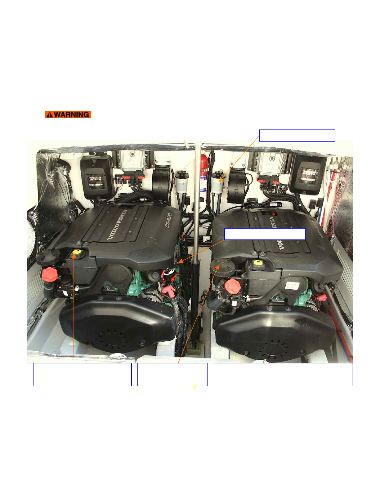
3.0 PROPULSION SYSTEM (Optional Volvo-Penta Twin 220A-DPS Engines Shown)
3.1 GENERAL Your 36z is propelled by twin Volvo diesel engines turning duo-prop propellors. The
dual-lever electronic control acts as a combination throttle and gear selector. Care should be taken when
shifting. Always allow the transmission to engage the new gear before throttling up. If the two levers are
set to within 200 RPM of one another, they will automatically synchronize.
The engine should never be running when swimmers are near the boat.
Engines are accessed by raising the cockpit hatch using the electric lift.
3.2 COOLING
Your engine passes seawater (raw water) through an intake in the sterndrive unit under the swim
platform to the impeller (pump) then through the raw water intake strainter then through a heat
exchanger where it cools the engine’s coolant. This coolant is circulated through the engine and
returns to the heat exchanger. For the engine to keep cool, it must have an adequate supply of
raw water and coolant.
RAW WATER
INTAKE STRAINERS
ENGINE OIL DIPSTICKS
Unscrew Cap when engine cold
to check COOLANT LEVEL
See Volvo D3 Operator’s Manual
for greater detail of engine components
GEAR OIL LEVEL

CHAPTER 3 PROPULSION SYSTEM
11
If you get a high water temperature alarm, most likely the raw water strainer has become clogged.
Check to be sure it’s clean first. Best to check the coolant level before embarking on your journey
by opening the caps on top of the engine. Coolant should be visible (reach it with you finger when
the engine isn’t hot) of the reservoir which is on top of the front starboard corner of the engines.
Do not attempt to remove the coolant cap of a hot engine.
For details on what type of coolant to use it is very important to, consult the Volvo-Penta operator
manual. As the water and exhaust exit out the back of the drives, it is not as easy to check raw
water flow. It is recommended to pay close attention to water temperature (167°-194° F is
normal) at the outset. Engine oil temperature should be running at less than 220 degrees F. It’s a
good idea to have a container of spare coolant aboard at all times.
3.2 NEW ENGINE BREAK-IN
While running the engine for the first time and after shut-down, check for proper engine oil
pressure, diesel fuel leaks, engine oil leaks, coolant leaks, proper operation of the indicators and
gauges, proper exhaust color, engine vibrations and sounds, If coolant or oil temperature is high
(a) Is the raw water intake seacock open at the base of the IPS drives? (b) Are the raw water
strainers clogged?
The engine may seize if it is operated when seawater intake is restricted or if
load is applied without allowing the water temperature (engine) to warm up.
During the first 10 hours of operation, full load should only be applied for short periods. Never run
the engine for a long period at a constant RPM during this period. Higher oil consumption is
typical at this time, so carefully observe oil pressure, oil temperature and coolant temperature,
exhaust color and check engine oil and coolant levels frequently... ie daily.
3.3 LUBRICATION
Both the engine and transmission use oil for lubrication. The transmission will tend to use less oil
than the engine, but both should be checked frequently. For the proper type of oils to use (which
may depend on the service area and conditions) consult the engine manual.
The engine oil may be checked on the port side of the engines by pulling up the red dipsticks, at
least ! hour after running of the engines to allow the oil to drain down from the upper part of the
engine.
The transmission oil levels can be seen in the reservoirs on the transom.
3.4 CORROSION PROTECTION
Read the Volvo Operators Manual (VOM) carefully. In addition to a transom zinc, there are zincs
on the sterndrive and engine. Pay close attention to these zincs, inspecting them with a diver at
least monthly…a good frequency for cleaning the bottom of optimum performance as well. You’ll
find that the timing for replacing zincs varies depending on the type of bottom paint used, the
characteristics of the seawater, the amount of electrical current in marinas, or could indicate (if
excessive wear is noted) an electrical short on the boat, etc. Inspect engine zincs periodically at
the time of oil changes and remove the corroded area on the surface, replacing them when
deteriorated to less than 50% of original size. Otherwise corrosion in the cooling system will occur
and water leakage or parts breakage will result. Be sure to close raw water intakes at before
removing a plug to replace a zinc.
CHAPTER 3 PROPULSION SYSTEM
12
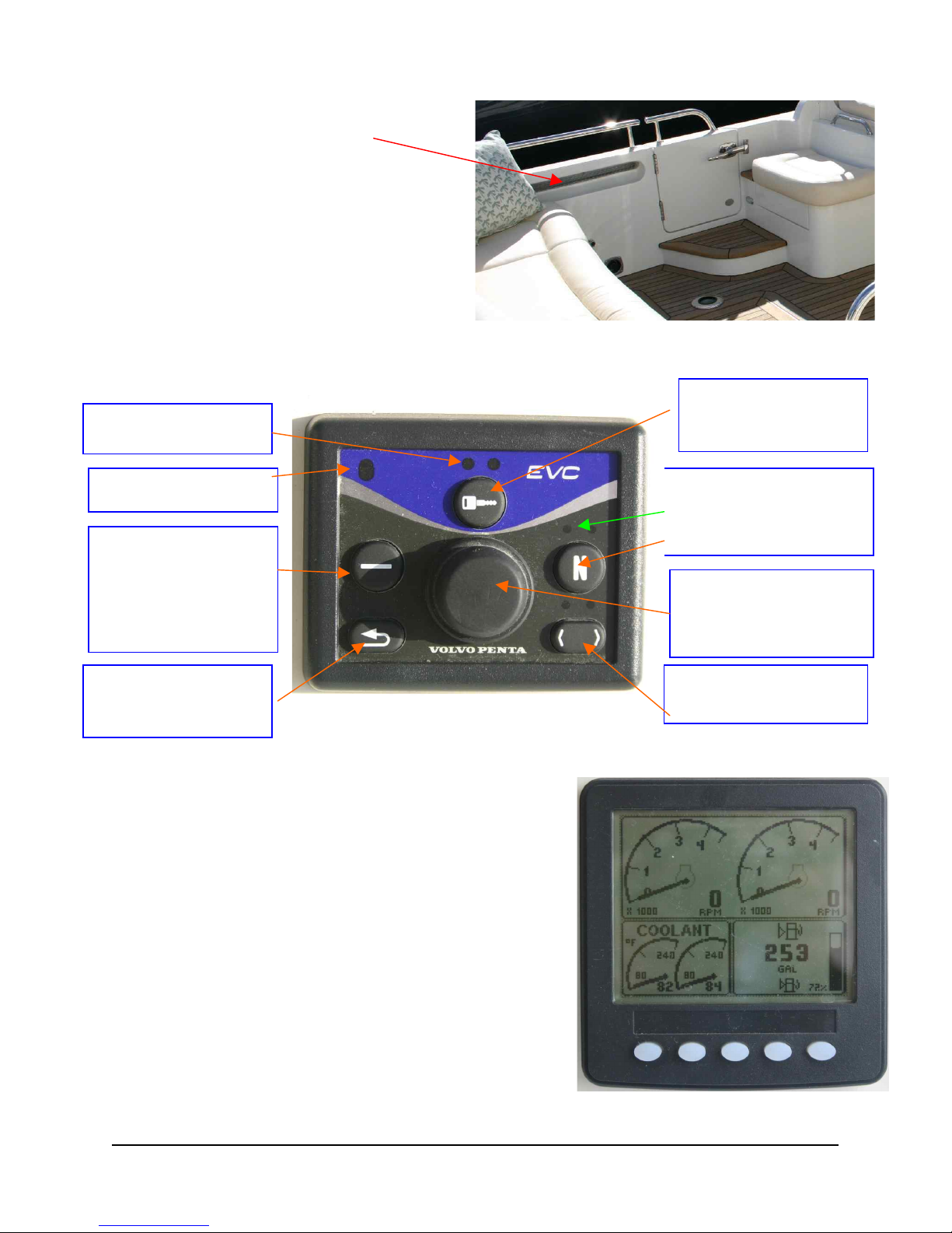
Activates Control
Panel. Push twice to
Lock.
BACK button returns
and steps up from submenus to main menu.
Push 1sec Backlight
Off or On. Adjust with
quick pushes. If pushed
on inactive station,
menu structure is
activated.
2nd Station Lock
NEUTRAL BUTTON Push
to Disengage Drives
Green LED = In Nuetral
No Light = Engaged
ENTER KNOB –Push in
to acknowlege alarms,
toggle menus, enter sub
menus & confirm choices
Red = Active Station
Flashing = Fault
Panel Selector – Not
applicable with one Panel
3.5 ENGINE AIR INTAKES
Diesel engines use a large
quantity of air for combustion. The
engine of the 36z gets this air thru
grills under the cockpit coaming,
both port and starboard.
3.6 VOLVO PENTA EVC-C CONTROL PANEL
This allows the operator to perform settings and choose information displayed on the engine
control LCD screen. See more detail in Volvo Operator’s Manual.
See VOM 16
3.7 EVC-C SYSTEM DISPLAY PANEL
This single display is used instead of traditional gauges.
When the engine keys are turned ON to the first position
detent (not hard right to START), the words “VOLVO
PENTA EVC” will show briefly.
This is the “C” version of the EVC Display, which means
you can customize the info to be displayed in the main
menu and it what form. The feature is called “My View”.
See VPOM .
ENGINE DATA (button 1) is programmed to show RPM,
Coolant Temp, Fuel Level on the 1st page, then will
show other info next time button is pushed such as
Gallons Remaining, Gallons per Hour, etc.
MULTI DATA (button 2) Shows operating info in 4
different windows. The user can choose the info to be
displayed as numbers or analog, shifting between modes as button is repeatedly pushed.
1 2 3 4 5
CHAPTER 3 PROPULSION SYSTEM
13
TRIP/FUEL (button 3) Shows Trip Fuel Used, Average GPH on Trip, Hours on Trip and Engine
Hours Total. Reset to “0” by pressing 3 seconds until beep heard.
GRAPHS (button 4) - Values can be established for a range of 2 minutes to 8 hours. Port
engine shown as black line and starboard as a gray line.
CONTRAST & MENU (button 5) Push for 1 sec to set contrast to one of five levels by additional
taps. Then EXIT.
Press Button for 5 seconds to access configuration menu, then navigate using up and down
arrows. Select with the right arrow. See VPOM page 20 for more information.
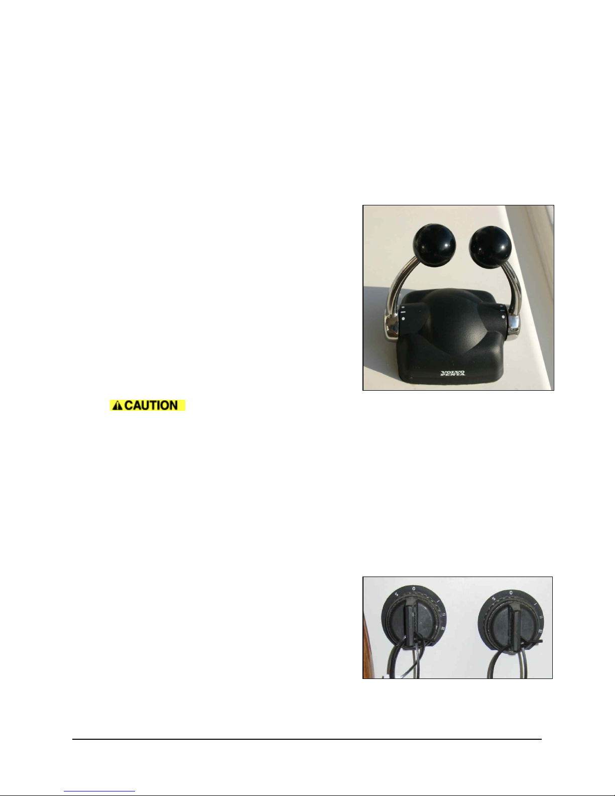
3.8 THROTTLE/SHIFT CONTROL
There 5 positions (front to back). FORWARD
IDLE FORWARD
NEUTRAL
IDLE REVERSE
REVERSE
The port and starboard engine RPMs will synchronize
automatically when within 200 RPM of each other.
Emergency Shifting If a fault occurs which prevents
electronic gear shifting with the control levers, it is
possible to shift manually using the procedure outlined
in the VPOM.
SUDDEN MOVEMENT HAZARD This control lever governs both throttle and
shifting functions. The boat may start to move abruptly when the marine gear is engaged:
Ensure the boat is clear of all obstacles forward and aft. Cautiously shift to the IDLE FORWARD
position then quickly back to NEUTRAL position. Observe whether the boat moves as you
expect.
3.9 START ENGINE
Before starting the engine, make sure (1) the raw water intake seacock over the IPS drive flange
is in the OPEN position (2) the raw water strainer is clean (3) the engine has sufficient oil and
coolant (4) transmission fluid is at the proper level (5) there are no restrictions to the air intake
grills (6) the fuel valve over the starboard tank is OPEN (8) the HOUSE and BOTH ENGINE
battery banks (under the electrical panel) are turned ON (9) the throttle is in the neutral position
showing the “N” Green Light on the EVC Control Panel (9) no one is in the water near the boat
and (10) all machinery space hatches are closed.
TURN ON ENGINE Turn the spring-loaded Ignition
Keys clockwise to the first detent a position I. The LCD
screen will momentarily show “Volvo Penta EVC”.
A long continuous beep indicates that the self-test
function has failed.
Ignore the top “key” symbol on the EVC panel which is
only activated for dual helm station boats.
START ENGINES by holding one then the second Ignition Key to the right with pressure to the to
position III on the outer key rim, for several seconds until the engine starts. Then release the key,

CHAPTER 3 PROPULSION SYSTEM
14
so it springs back to position I. The engine will not start unless the shift levers are in NEUTRAL.
If repeated start attempts are needed, the key must be turned back to position 0 first.
Never engage the starter motor (turning key hard to the right) while the engine
is running. This may damage the pinion and/or ring gear.
IF BATTERY VOLTAGE is low and you have difficulty turning over the engine, a momentary
Parallel Switch is located to the left of two Engine Start Battery Switches underneath the electrical
panel belowdecks. By turning this switch on, you add the capacity of the house bank to the start
battery. Once started, turn OF the Parallel Switch. It is for emergency use only.
TO REV THE ENGINES out of gear. Push the “N” button on the EVC Control Panel until. The
green light over “N” flashes to acknowledge shift is disengaged. To disengage the Neutral
function for normal operation. Push “N” button. A steady green light acknowleges. Never race the
engine when it is cold.
3.10 ALARM DISPLAY
When the ignition key is first turned ON to position I, you may hear an audible alarm signal and
see a “Stop Sign” appear on the EVC Display, indicating that the diagnostic function has
registered a malfunction.
PRESS the center knob once on the EVC Display to acknowledge the alarm. When the fault has
been acknowledged, the audible warning will become silent and the source of the problem
indicated on the display. Please refer to Volvo Operator’s Manual chapters for detailed
information about FAULTS and recommended action starting on page 40 of the VPOM.
3.11 STOP ENGINE
Put both engine controls in NEUTRAL.
Turn & hold the spring-loaded Ignition Key with pressure to the left to position S until the engine
stops. If unsuccessful, there’s a clearly labeled “Emergency Shutdown” button in the upper middle
port side of the engine.
Make sure to turn OFF Engine Battery Switches under the electrical panel when leaving the boat.
Engine Stop & Restart after Crash-Stop If the engine otherwise stops, the following procedure
for re-start must be followed.
1. Put control lever in NEUTRAL
2. Acknowledge any ALARM by pressing the center KNOB on the EVC Panel.
3. TURN & HOLD ignition switch left to OFF until all lamps have gone out.
4. Then TURN the ignition system to the ON (not the engine Start) position only.
5. Acknowledge any ALARM by pressing the center KNOB on the EVC Panel.
6. START the engine by: TURNING & HOLDING the ignition switch to the right.
7. STOP the engine. Wait again until all lamps have gone out.
8. RESTART the Engine.
3.12 OPERATION
Engine trouble can arise if the engine is operated for a long time under
overloaded conditions at max RPM. Recommended “Max Cruising Speed” is at least 10% below
full throttle of 3400-3600 RPM. While running, pay attention to the engine gauges on the LCD
display. A significant change in temperature, oil pressure, or voltage should be investigated
immediately, before the engine is damaged.
OIL PRESSURE – Normally between 4.5 and 5 bars, except lower when idling

CHAPTER 3 PROPULSION SYSTEM
15
COOLANT TEMPERATURE – Normally between 167 and 194 degrees F. 36z #4 runs at about
181 degrees at 25 knots
OIL TEMPERATURE – This should be less than 220 degrees F, or 105 degrees Celsius.
CHARGING – Normally about 14 Volts when underway.
Depending on hull structure and engine installation, engine and hull resonance may be greater at
some speeds than others. This is normal and you will learn to pick the sweet spots. If you hear
any abnormal sounds, stop the engine and inspect.
If any warning lights or buzzers activate, stop the engine immediately.
Determine the cause and repair the problem before continuing to operate.
CHAPTER 4 STEERING CONTROL SYSTEM
4.0 STEERING SYSTEM
The 36z has an integrated, electronically controlled power steering system, which through electric
motors rotate the two sterndrive units mounted on the transom. When running, the 36z is steered
as with outboards. Thrust of the propellers is directed more immediately and precisely from side
to side through a 26° arc to steer the boat.... rather than bouncing the prop wash pf a
conventional straight shaft propulsion unit off a rudder.
When the throttle/shift levers are put in (N) neutral and the left-hand button pushed to activate the
joystick: Control of the pod drives is transferred from the throttle/shift levers to the joystick that
controls the steering computer. When the joystick is activated, the steering wheel is inoperative.
Emergency Alignment If a fault occurs which prevents one or both of the sterndrives from
being operated with the steering wheel, it is possible to align the faulty propulsion unit(s) so that
its aimed straight ahead (and won’t act like a rudder), so as not to impair operation of either the
remaining propulsion unit or the steering of the boat with the two engines. See the VPOM.
Emergency Steering These controls are attached to the engine with cables, so if the electronic
steering ever failed on both propulsion units, a steering method using the two engines can be
employed. This is outlined in the VPOM.
Emergency Shifting In an emergency, you should be able to shift the drives manually. There
is a shift actuator that normally shifts the mechanical drive, if that is not functioning, you can
remove the cable from the shift actuator and manual push/pull the cable to shift into gear.
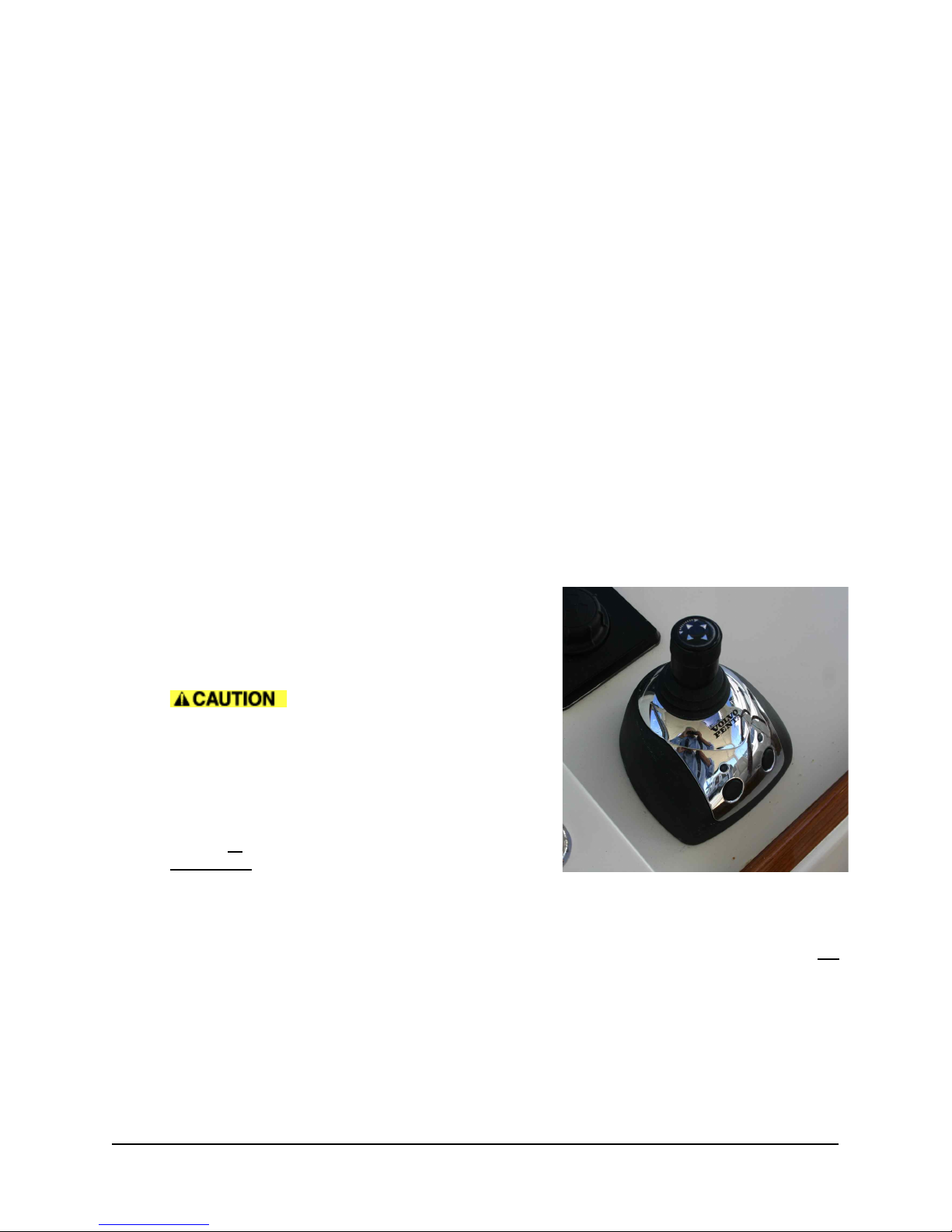
4.1 JOYSTICK DOCKING CONTROL
This control is used only for docking and maneuvering
at slow speed. Learn to handle the joystick in a safe
and correct manner before you start using the function
in tight quarters.
When the joystick is active, the
normal engine controls are Neutral and inactive. A
computer operates the drives and shifting. Rotation of
the wheel is frozen and it should not be turned, as
damage may occur.
To Activate: Both engines must be running and the
engine control handles must be IN NEUTRAL. Press
the left (L) button. A beep confirms it is active and the
light above will go on.
To DeActivate: Either move the engine controls OUT OF NEUTRAL (forward or reverse) or
press the left (L) button again. A double beep will confirm that it is OFF.
Boost Function In windy weather or current when you need more oomph, push the right (R)
button. A beep will confirm it’s engaged. Deactivate by pushing the button again. The light above
will go on and you’ll hear double-beep confirmation.
Maneuvering with Joystick Follow the arrows. Lean the joystick post in the direction you’d
like to go. Release and the thrust stops. The boat may keep moving, so you may have to tap it in
the opposite direction to stop it. The top of the joystick is rotated (twisted) to orient the bow and
stern, or to spin the boat completely around on its own axis. Pretty simple Takes some practice
until it becomes completely intuitive.
R
L
 Loading...